
Abstract
Background:
The green ship technologies are gaining in importance in diverse areas of ship design.
Objective:
To explore the energy-saving and environmentally friendly ship during the primary ship designs stage.
Methods:
A hull form optimization method based on the full parametric modeling is proposed, in which the Computational Fluid Dynamic (CFD) analysis is integrated, and the algorithms of Sobol and NSGA-II are used. Taking a 674 m3 single trawler as an example, the full parametric modeling of forebody hull form is adopted by employing an F-spline curve with the software CAESES and the total resistance of the full-scale ship is computed by the integrated software SHIPFLOW numerically.
Results:
It is proved that the presented optimization method can engage well in the automation process of the hull form design under the constraints of displacement and longitudinal center of buoyancy. Compared with the initial hull form, the total resistance of the optimal ship at the design speed of 11.5 kn decreases 12.2%.
Conclusions:
It indicates that the proposed method of hull form optimization based on full parametric modeling proposed in this paper has better engineering applicability and broad application prospect in practical ship design practices.
Introduction
With the fluctuating cost level of the fuel and the strict implement of the Energy Efficiency Design Index (EEDI) proposed by the International Maritime Organization (IMO), the green ship technologies are playing a more and more important role in the diverse areas of ship design. As an essential part of the ship design, hull form optimization is one of the key technologies affecting the energy saving and consumption reduction.
The traditional ship design process is the design spiral, a basic concept proposed by Evans [5] giving the clear representation of the design procedure and demonstrating the sequential and repetitive of a series of design tasks. Ship design is a synthetic discipline. The traditional repetition circle of design is a process of gradual deepening and approximation. The reasonable results meeting the main technical requirements of the design regulations can be obtained by the traditional method. But the final result is strongly relied on the parent ship data and heavily depended on the designer’s experience. Moreover, it is a time-consuming process, and the results space is limited. With decades of practice and experience accumulation, the traditional design method has been preferred in conventional design, but meanwhile it is difficult to make any breakthrough in ship performance optimization as to the above limitation.
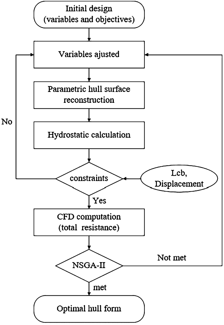
Along with the advances in technology, modern approaches to ship design have been gradually transformed to the methodology of simulation-based design (labeled as SBD) [17] which is combined with geometry reconstruction technique, CFD simulation and optimization technique, etc. The basic framework of the SBD method is as shown in Fig. 1. The SBD methodology breaks the limitations of traditional hull form design and realizes the direct optimization of it. At present, it has been widely used in ship design, and was listed as one of the important directions of research in the future in the 26th session of ITTC Resistance Committee [22].
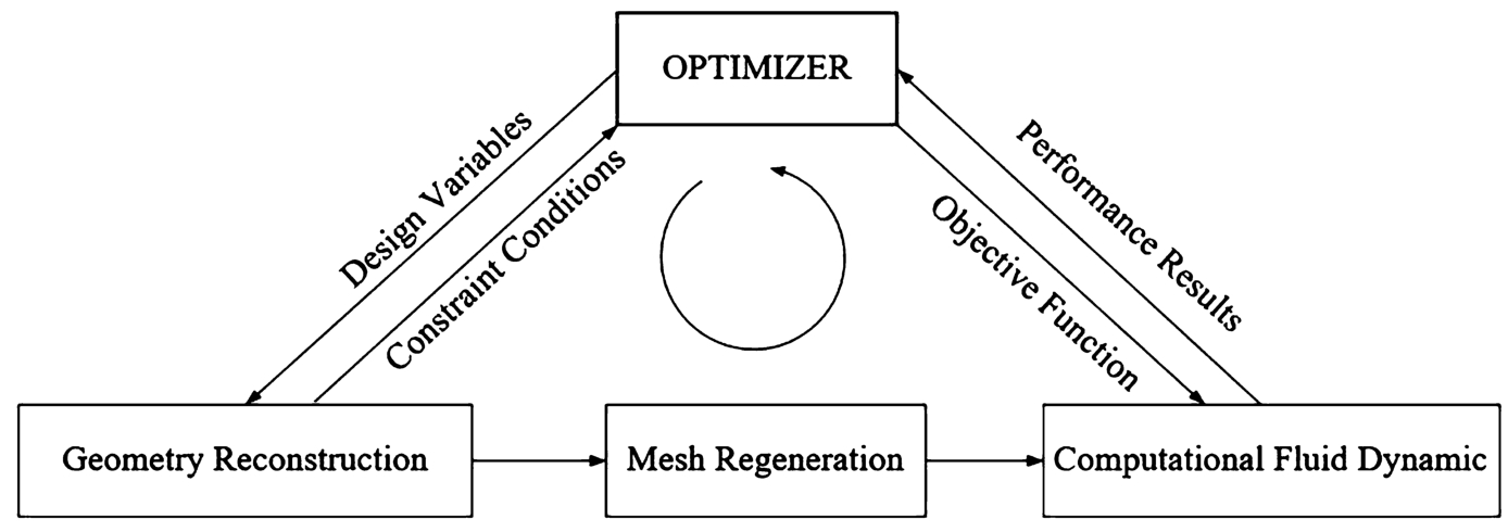
The basic framework of the SBD methodology.
The SBD methodology is implemented through appropriate software platforms and tools and has been conducted on its various branch technologies by a lot of researches. Particularly a series of systematic studies on the various technique of SBD was carried out by professor Campana and his team [3] from INSEAN Pool in Italy. This paper mainly concentrates on the application of the parametric design method to the hydrodynamic hull form optimization. At present, parametric modeling methods of hull form mainly include the following: conventional Lackenby transformation method [15], morphing approach [12,25], Bezier Patch approach [17,19], free-form deformation method [18,23,26], CAD-based approach, parametric modeling approach, etc. In the field of parametric hull form research, Harries [8] firstly applied Lackenby transformation to the design of an LNG carrier, using the relevant parameters of the ship’s cross-section area curve as variables to achieve parametric deformation of the hull. Harries and Abt et al. [1,9–11,27] developed a commercial modeling software FRIENDSHIP-Framework (now called CAESES) to study the parametric modelling and the hull form deformation of various ship type. Peri et al. [20] optimized the bulbous bow by using NURBS surface modeling and achieved ideal results. Peri and Campana [17] adopted Bezier Patch approach to achieve the transformation of the bulbous bow and the total resistance of the optimal ship was reduced by about 3%. Kim et al. [13] combined the Lackenby transformation method and the radial basis function-based transformation technique to carry out the whole and local transformation of hull form of series 60 respectively. Han et al. [7] conducted the hydrodynamic optimizations of ship hull forms for an ultra-large container ship and the forebody hull form of an LPG carrier by employing the F-Spline curve to study distortion transformation and form parameter design. Deddy Chrismianto et al. [4] investigated the parametric design of a bulbous bow in a solid modeling procedure using of the cubic Bezier curve and curve-plane intersection methods. Bolbot and A.Papannikolaou [2] performed a multi-objective optimization of the bow form of the standard ITTC KVLCC2 tanker where the parametric geometry model of ship’s bow region and optimization process were developed with the software CAESES. Yu lu et al. [16] described an methodology which adopted the parametric form approaches based on improved genetic algorithms for the hydrodynamic optimization of a ship bulbous bow. Kim et al. [14] carried out the hull-form variation through parametric modification functions and the hull form was optimized by the particle swarm optimization algorithm. Alexandros Priftis et al. [21] proposed a developed methodology which focus on multi-objective optimization of a parametric containership design and is implemented on CAESES software. Jianwei Wu et al. [29] utilized a free-form deformation and shifting method to generate a series of realistic parametric hull forms of DTMB5415. Zhi Zong et al. [30] conducted the hull form optimization of trimaran with a ship hull modification method called self-blending. Guan guan et al. [6] proposed a parametric design of hull surface based on energy optimization which is used to get the expression of the hull fairness surface with NURBS, providing an alternative to traditional design method of hull form and improving the efficiency and quality of the design for ship form. Sotiris Skoupas et al. [24] proposed an integrated methodology for the parametric design and optimization of high-speed Ro-Ro Passenger vessels of both mono- and twin-hull configuration. Penghui Wang et al. [28] developed a four-objective optimization system which is mainly composed of the uniform design, free-form deformation method, radial basis neural network and a series of genetic algorithms(GAs) and was applied to a deep-sea aquaculture vessel.
To sum up, some hull form transformation methods were proposed for the purpose of performances optimization. And the different modern hull form optimization methods are applied to many types of ship gradually. In recent years, with the increasing demands of fisheries development, the higher requirements for the energy-saving, economy and environmental friendliness as to the fishing vessels begin to be put forward. The preferred and essential way is to reduce the resistance of shipping thus saving the fuel cost, which can be solved through the hull form optimization. Studies for the hull form optimization of fishing vessels have also been developed with traditional and modern approaches. However, there are still not many researches on the hull form optimization based on the full parametric modelling of the fishing vessels which can achieve the widest geometric design space. Generally, the classical fishing vessels with bulbous bow have some own features different to the classical cargo ships, such as having the designed trim, no parallel mid body, no flat bottom line but flat keel with a certain width, etc, making it a little difficult to build the full parametric modeling for transformation. To explore the hull form transformation of this type of ship, a single trawler representing the classical fishing vessel with bulbous bow is studied to conduct an automatic process of hydrodynamic optimization with a hull form optimization method. This method is mainly based on the full parametric modeling, integrating with the computational fluid dynamic (CFD) technique and utilizing the algorithms of Sobol and NSGA-II. And this paper is structured as follow. Sections 1 and 2 give a clear representation of the full parametric modeling of the forebody of hull form by employing an F-Spline curve with the software CAESES. The hull form optimization process is explained in Section 3. The optimization results and the final conclusion are presented in Section 4 and 5 respectively.
A curve is composed of a set of given data elements. These data elements usually are just a subset of the properties of the curve shape. Therefore the more different the definition of the expression curve function is, the more different the curve generated by the data elements may be. That is, the choice for expressing a curve with the related mathematical function brings about the curve generation result. In the full parametric modeling of this research, a fairness-optimized parametric curves with constraints, labeled as F-Spline, is used. These curves are based on the mathematical representation of B-spline curves and are generated by the fairness optimization process with a set of form parameters as constraints. In the process of parametric design of the ship shape, these fairness-optimized parametric curves with constraints have been employed as the transformation functions for the distortion transformation.
In the present research, F-Spline is widely used as a constrained transformation function for the basic curves of the hull surface. The F-Spline is an important kind of curve in the software CAESES due to its parametrization properties. It is a quite handy multi-purpose curve which can be applied in many modeling situations. For F-Spline curve, the designer has to specify at least the start and end position. Furthermore, the tangent angles, area and centroid information of the closed region related to the curve can be set. As shown in Fig. 2, the required shape of F-Spline curve is achieved by the form parameters including the start and end position, tangent angles, area and centroid information.
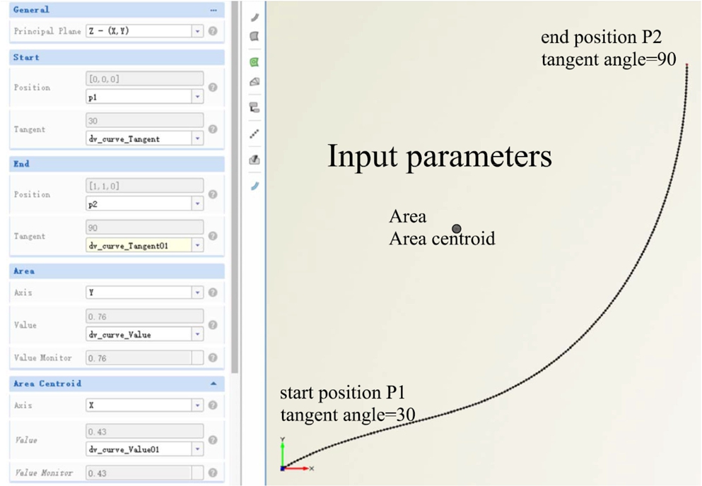
The example of F-spline curve.
With the use of the F-Spline curve, the basic curves can be expressed with less form parameters while ensuring the curve shape correct, so the F-Spline is the foundation for the full parametric modelling in software CAESES. In CAESES, three main concepts are important for the realization of the full parametric modelling: Feature Definition, Curve Engine and Meta Surface. Feature Definition is often used to define the sectional curve, it is requiring the input arguments and the function. The function is a command sequence to define the sectional curves concretely with the related input arguments. Hence the definition of sectional curve designed with input arguments (positions, tangent angles, areas, etc.) can be encapsulated in the Feature Definition. In the next step, importantly, we should build the basic curves to give the values (positions, tangent angles, areas, etc.) of the sectional curve at different locations according to the input arguments in Feature Definition before a series sectional curves generated by the Curve Engine. The F-Spline curve comes in handy. The basic curves (positions curves, tangent angles curves, etc.) can be expressed by the F-Spline curve with the form parameters. By the way, the form parameters here can be selected later by the designers and used as design variables to perform the shape optimization. The Curve Engine is completely defined by the correlated Feature Definition and the related basic curves. After that, the Meta Surface combined the Curve Engine can sweep along the series generated sectional curves among the specified start and end position range to form a smooth parametric surface.
More details are stated for the further comprehension of the Meta Surface. The Meta Surface is commonly used for parametric sweeps along a given path, direction or range. When executing any kind of curve definition program, the surface shape can be further controlled by multiple curve parameters. It is well applied to surface modeling of ship hulls, blades, diffusers, wings, ducts and many more. Typically, these kinds of surfaces can be based on a 2D contour or profile description which consists of a set of parameters like radius, length, angle or parameters about area. Meta surfaces control such key parameters by functions defined in the sweeping range. Finally, such functions are then varied in design studies and optimization processes.
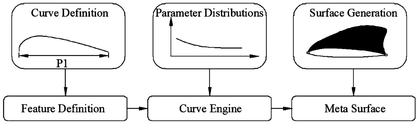
A simple parametric modelling process of wing.
A simple but typical parametric modeling of a wing is illustrated in Fig. 3. The 2D profile is designed first with a single length parameter called “P1”. This curve is then encapsulated in a feature definition. In a next step, a function is created that controls the values of “P1” within the sweeping range. The profile and its functions are then connected via so-called curve engines. Finally, a meta surface is created which is based on the curve engine.
A simple parametric modelling example is illustrated as above. It seems to be easy, but the fact is that a complex surface like ship hull is hard to be modeled. In this research of parametric modeling of hull form in software CAESES, the basic longitudinal characteristic curves expressing the main properties of hull form are firstly generated by using the F-Spline curve which is geometrically optimized for fairness, and then a series of transversal sections of hull form can be further generated with a group of Feature Definitions and corresponding Curve Engines. Finally, a set of smooth parametric surfaces, which interpolate or closely approximate the design sections are generated by the Meta Surface. Figure 4 shows the full parametric modeling process of the hull form in CAESES.

The full parametric modelling process of hull form in CAESES.
The basic curve of the hull form is formed by the form parameters, and the form parameter values describing each basic curve are extracted from the given initial hull form. Therefore, full parametric expression of arbitrary hull form can be realized by selecting and combining a group of form parameters appropriately. And generally, the number of form parameters strongly depends on the shape variation strategy. A well-developed structure of parameter dependencies can help to avoid unnecessary number increasing of parameter inputs and degeneration in hull form variation.
The combined parametric surfaces form a complete representation of the hull form. Therefore, it is possible to efficiently and effectively change the shape of hull form surface based on parametric transformation. It should also be noted that there are many form parameters that constitute the basic longitudinal characteristic curves and possible correlation among them, so it is not easy to determine the parametric input data sets. In general, the more flexible the basic curve design desired, the more complex the design process will be.
The full parametric modeling of forebody hull form. The full parametric modeling method almost integrates all the necessary conditions for the distortion of the hull surface. The adjustment of the hull form parameters will be reflected in the change of the hull form, and the more hull form transformation results can be attained through the full parametric modeling method than the general hull form transformation method with less form parameters. So the full parametric modeling method can provide the wider geometric design space for the hull form optimization. In the study of hull form optimization, the full parametric modeling method is applied to the modeling of the forebody hull form of a single trawler, while the aft-body hull form remains unchanged in the subsequent optimization process.
To extract and build the basic longitudinal curves from the initial hull form, analyzing the main characteristics according to the specified ship type is the first step. Comparing to the common ship type like the KCS, the studied ship is this paper has some different characteristics. The single trawler has the design trim, transom stern, a bulbous bow, no parallel mid body, no flat bottom line, but the flat keel has a certain width.
In order to establish the basic curves and build a well-developed structure of parameter dependencies, the basic curves are mainly extracted from the studied ship and classified into following three categories.
Basic geometric curves
Such basic curves include center plane curve, flat keel line, flat of side curve, design waterline, deck line, stem line. For the bulbous bow, the basic geometric curves include upper and lower center plane curves, the max beam curve and the related max beam elevation curve. These curves provide the positions information for the input arguments of the corresponding feature definition.
Basic area curves
This type of basic curve mainly refers to the sectional area curve labeled as SAC. Optional curves for centroid of sectional area may also be included with need. The SAC mainly provides areas information for the input arguments of the corresponding feature definition.
The SAC is an important curve as it is close to the hydrodynamic performance of a ship and meanwhile possesses the simple and effective description of global geometric properties. From this point of view, the ship hull form distortion approach based on SAC transformation is one of the most effective global design methods for the preliminary design stage.
Basic tangent angle curves
This type of basic curve provides the tangent angles information for the input arguments of the corresponding feature definition, mainly including the flare/tangent angle information at the interception points which the sectional curve intercept with the keel line, the waterlines and the deck line along the ship length direction.
Once the basic curves are established, the parametric surface of forebody is divided into several parts according to the feature definition of the sectional curves. With the tool of the Curve Engine and Meta Surface, a complete parametric surface of the forebody hull form is produced. Figure 5 shows the basic longitudinal curves which define the essential shape characteristics of the forebody and the bulbous bow. These basic curves are all defined in the Z-X plane. Figure 6 shows a three-dimensional view of the parametric hull surface generated. For the sake of better presentation, the z-coordinate of curve Z = X and the tangent angle curves are multiplied by suitable factors k respectively.

The basis curves of hull form.

The views of parametric hull form.

Bodylines comparison of the traditional and parametric forebody hull form.
The widest geometric design space for the hull form optimization may be achieved with as few design variables as possible by the full parametric modeling. But it should also be noted that the parametric ship hull is just the approximate expression of the actual ship hull. The key of the problem is to build the parametric hull form as close to the actual ship hull as possible and to ensure a certain modeling accuracy. A comparison of the sectional frames of the forebody among the traditional modeling and the parametric modeling is demonstrated in Fig. 7. And the hydrostatic calculation results between the traditional and the parametric modeling are compared with each other in Table 1. In term of the results, there is a small difference of the bodylines between the traditional and parametric modeling ship. Furthermore, the deviations of the hydrostatic calculation results are small and meet the requirement of modeling accuracy obviously.
Comparison of hydrostatic calculation results
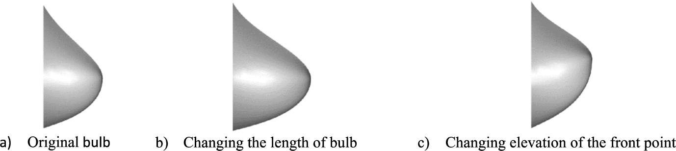
Parametric model of bulbous bow.
To have a similar view of the distortion transformation with the form parameters, the parametric model of bulbous bow is taken as an example. See Fig. 8, the bow becomes longer when we increase the length of bulb, and the bow heaves up when we increase the elevation of the front point. It indicates that the full parametric model can be applied well to the hull form transformation of the practical ship with the control mechanisms of the set of reasonable form parameters.
Mathematical model of hull form optimization
The full-scale ship for instance in this paper is a single trawler with a design speed of 11.5 Knots and the related Froude number is 0.297, which is a medium & high speed ship. The main dimensions are shown in Table 2.
The main dimensions of the single trawler
The main dimensions of the single trawler
The optimal design of hull form is essentially a problem of mathematics optimization. It mainly includes three basic elements: objective functions, design variables and constraints.
This ship sails at design draft condition most of the time when manoeuvring with fishing nets, so the object of the shape optimization of the forebody hull form is to minimize the full-scale total resistance under the design draft condition, while ensuring that the relevant geometric constraints are under the design requirements. That is, the main dimensions keep unchanged, the displacement and the longitudinal position of the buoyancy center meet the constraint requirements according to the physical demand. The mathematical model of hull form optimization based on CFD is as follows.
In the formula, the objective function
Since the functional relationship between the objective function and the design variables is implicit and unknown, it is necessary to conduct the implicit calculation depended on the CFD so that building a solvable mathematical model of the optimization problem. In this study, the total resistance is obtained by the CFD tool SHIPFLOW. Here giving a brief CFD computation theory introduction of the software SHIPFLOW. SHIPFLOW divides the total ship resistance into three resistance components (including frictional resistance, viscous pressure resistance and wave resistance) and computes them separately through the XBOUND, XCHARP and XPAN modules based on different theory separately.
With the technological thought of SBD, a complete optimization process is established by coupling the CAD software CAESES and CFD software SHIPFLOW, integrating the application of algorithms Sobol and NSGA-II.
The automatic optimization of hull form can be mainly separated with two steps. The first step is to conduct the Design of Experiments (DoE) procedure which uses Sobol algorithm to have a sensitivity analysis and explore the design space of the system. The main purpose of the exploration is to determine the effect of each selected form parameter on the hull form variation and thus on the hydrodynamic performance, finally to provide a set of relatively reasonable initial values of the selected form parameters and feasible parameter ranges for subsequent optimization procedure.
Based on the relatively reasonable set of initial values of design variables, the deterministic optimization is performed with the algorithm NSGA-II. The hull form automatic optimization process is shown in Fig. 9. The geometry of the hull surface can be reconstructed automatically by adjusting the design variables of the full parametric model. If the Δ and
The hull form optimization process.
Design variables of hull form and the initial and optimal values
This paper aims at optimizing the forebody hull form, and the aft-body hull form remains unchanged. The main design variables name, the related variable descriptions and the corresponding range are shown in the first two columns of Table 3. According to the design experience, the total resistance of the ship is very sensitive to the shape variation of the SAC curve, waterline, and the bulbous bow, so the form parameters of these basic curves are partly selected as the design variables. Along with about one month iteration of algorithm NSGA-II, A relatively optimal hull form scheme is obtained, see Fig. 10. The optimal values of the design variables are shown in Table 3. Table 4 shows the comparison of relevant constraint parameters before and after optimization. It indicates that the displacement, the longitudinal buoyancy center and the wet hull surface area of the optimal ship have a very small change compared with the initial values.

The iteration process of optimization with algorithm NSGA-II.
Comparison of the constraint parameters of the initial and optimum hull form
The calculation results of resistance before and after optimization are shown in Table 5. It can be seen that the total resistance
The calculation results of water resistance (
)
The calculation results of water resistance (
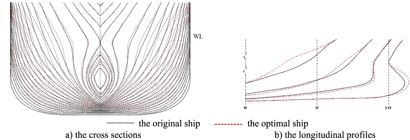
Comparison of the optimal forebody hull form and initial hull form.
As we can see from the Fig. 11, the forebody profile and the bulb shape are both different from those of the original one. In Fig. 11(a), it is found that the volume distribution around the design draft is considerably reduced while the volume around the bottom area is increased. In Fig. 11(b), we can find that the length of bulb is a little longer than the original one and the elevation of the front point at bulb is a little higher. All geometrical constraints are satisfied.
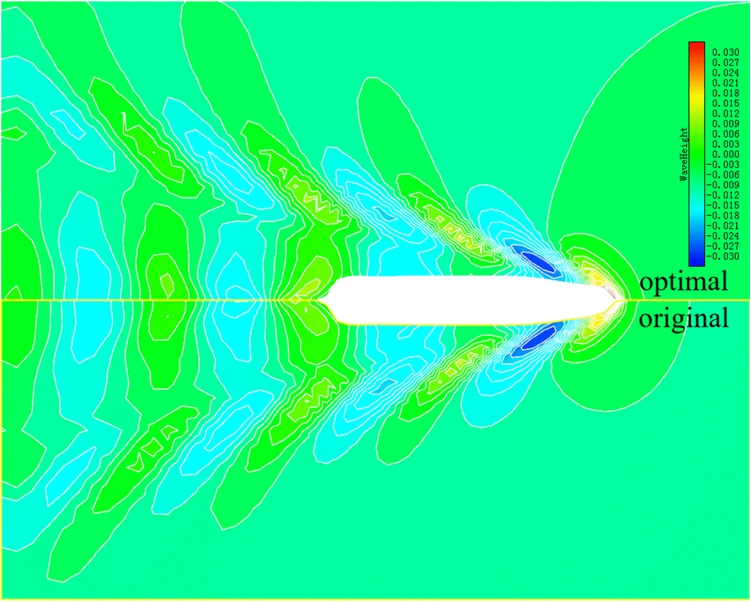
Wave contour of both hull forms (original and optimal design) at 11.5 knots.
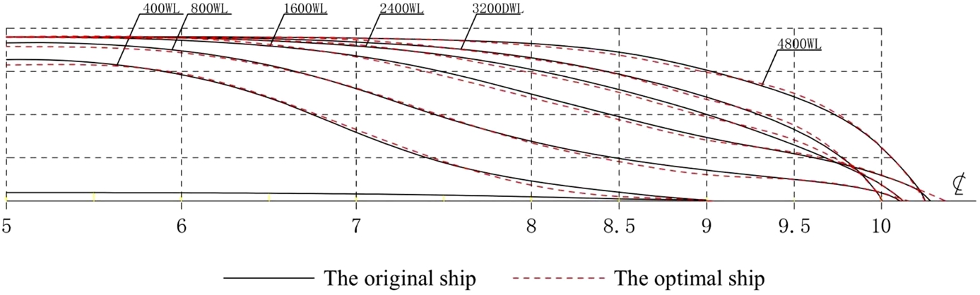
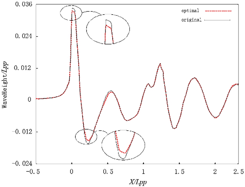
Comparison of waterlines of the optimal and initial hull form.
Comparison of the wave pattern between of the optimal hull form and the initial one.
The wave contour in the design draft condition is shown in Fig. 12 for the original and optimal ship. A decrease of 12.2% in the total resistance in the design draft condition is achieved. In Fig. 13, the selected design features a longer bulbous bow, a finer entrance angle and a thinner waterline that is expected to decrease the wave height in the design draft condition at around 11.5 knots. The comparison of the wave pattern between of the optimal hull form and the initial one is illustrated in Fig. 14.
With the idea of SBD, a complete hull form optimization procedure is carried out by coupling the full parametric modeling platform CAESES and the CFD tool SHIPFOW, utilizing the algorithms of Sobol and NSGA-II. Taking an example of a single trawler with bulbous bow, a full parametric modeling of the forebody of ship is conducted and the hull form optimization is performed around 11.5 knots under the constraints of displacement and longitudinal center of buoyancy. The optimization method is proved to be feasible and effective for the result that the overall resistance performance of the ship has been significantly improved. It suggests that the method mentioned above has a better engineering practicability and provides a good reference for the ship designers to obtain a hull form scheme of excellent performances. The ship model resistance test for the original and optimal hull form is needed to be carried out for the further reliable validation of results in the future.
Footnotes
Acknowledgements
I would like to show my deepest gratitude to my supervisor, Dr. LU Cong Hong, a respectable, responsible and resourceful scholar and professor, who has provided me with valuable guidance in every stage of the writing of this paper. Her keen and vigorous academic observation enlightens me not only in this paper but also in my future study. I shall extend my thanks to Dr. LIU Qiang, Dr. YU Xin, Mrs. FAN Wei, Mr. PENG Bi Ye for their kindness and help.
Funding statement
Special Fund for Marine Economic Development (six Marine industries) of Guangdong Province (GDNRC[2021]42)
Project for Southern Marine Science And Engineering Guangdong Laboratory (Zhanjiang) (011Z21001)
Conflict of interest statement
The authors have no conflict of interest to report.
Author contributions
Conception: WU Hao; LU Cong Hong; LIU Qiang; YU Xin; FAN Wei; PENG Bi Ye
Performance of work: WU Hao
Interpretation of data: WU Hao; LU Cong Hong; LIU Qiang
Writing the article: WU Hao; LU Cong Hong
All authors mentioned above have the access to the data.