
Abstract
A partial inverse design is introduced to derive a mutually coupled two-phase reluctance machine concept. The inverse design part begins with the torque as a function of inductance and current. For given torque characteristics the required inductance characteristics are calculated and including a magnetic circuit yields required reluctance or permeance characteristics for the air gaps. Such inverse design focuses on possibilities of reluctance machines in general, independent of any machine geometry. The derived two-phase motor concept uses self and mutual inductance independently to obtain up to four shifted harmonic torque characteristics. This allows to generate a bidirectional torque at every rotor position. Thus, there is no self-start problem and reduced torque ripple. The theoretical operation is shown with a linear magnetic circuit model and non-linear FEM calculations for a 2D and a 3D machine design.
Introduction
If we want to build a (switched) reluctance motor (SRM), that can produce a positive and negative torque at every rotor angle, what is the minimum phase number? While some might say three [1], much literature does not directly address this issue, but the three-phase example is often seen in textbooks, too [2, 3].
Torque characteristics
SRM are operated in a mode with only current on or off. So the phase current is constant. (This low cost operation mode is not optimal and only used for explanation here.) For those constant phase currents the reluctance machine produces a torque that changes with the rotor angle, forming a torque characteristic. Common SRMs have negligible mutual coupling and decoupled current control for each phase. There, only the self inductance is used to generate a torque. This provides only one torque characteristic per phase.
Using the same iron geometry different types of current excitations have been developed, which also provide only one torque characteristic per phase. A different connection of the coils results in a mutually coupled SRM (MCSRM) which requires both, mutual and self inductance, to be described properly [4].
Figure 1 summarizes the most important current distribution patterns for the common SRM geometry. The fully-pitched MCSRM [5] has nearly constant self inductances and only the mutual inductances change with the rotor angle. There, only the mutual inductance contributes to the generated torque. The flux switching motor [6, 7] is the two-phase version of it, but only for unidirectional operation and with asymmetric poles. The fractionally-pitched MCSRM also uses three phases [8]. All these provide only one torque characteristic per phase.
Geometry and elementary magnetic circuit for different excitation patterns. (a) SRM. (b) Concentrated winding MCSRM. (c) Fully-pitched MCSRM.
To produce a positive and negative torque at every rotor angle, there must be an applicable overlap of the torque characteristics. This is not yet the case for two symmetrical torque characteristics [9]. Thus, a common SRM needs three phases A, B, C, as in Fig. 2a. It is important to note that actually three different and properly overlapping torque characteristics are needed, having a 1:1 relation with their phases in common reluctance machines only.
Sketched torque characteristics of reluctance machines. (a) Symmetric decoupled three-phase SRM. (b) Symmetric decoupled two-phase SRM. (c) Asymmetric decoupled two-phase SRM. (d) Possible two-phase MCSRM example.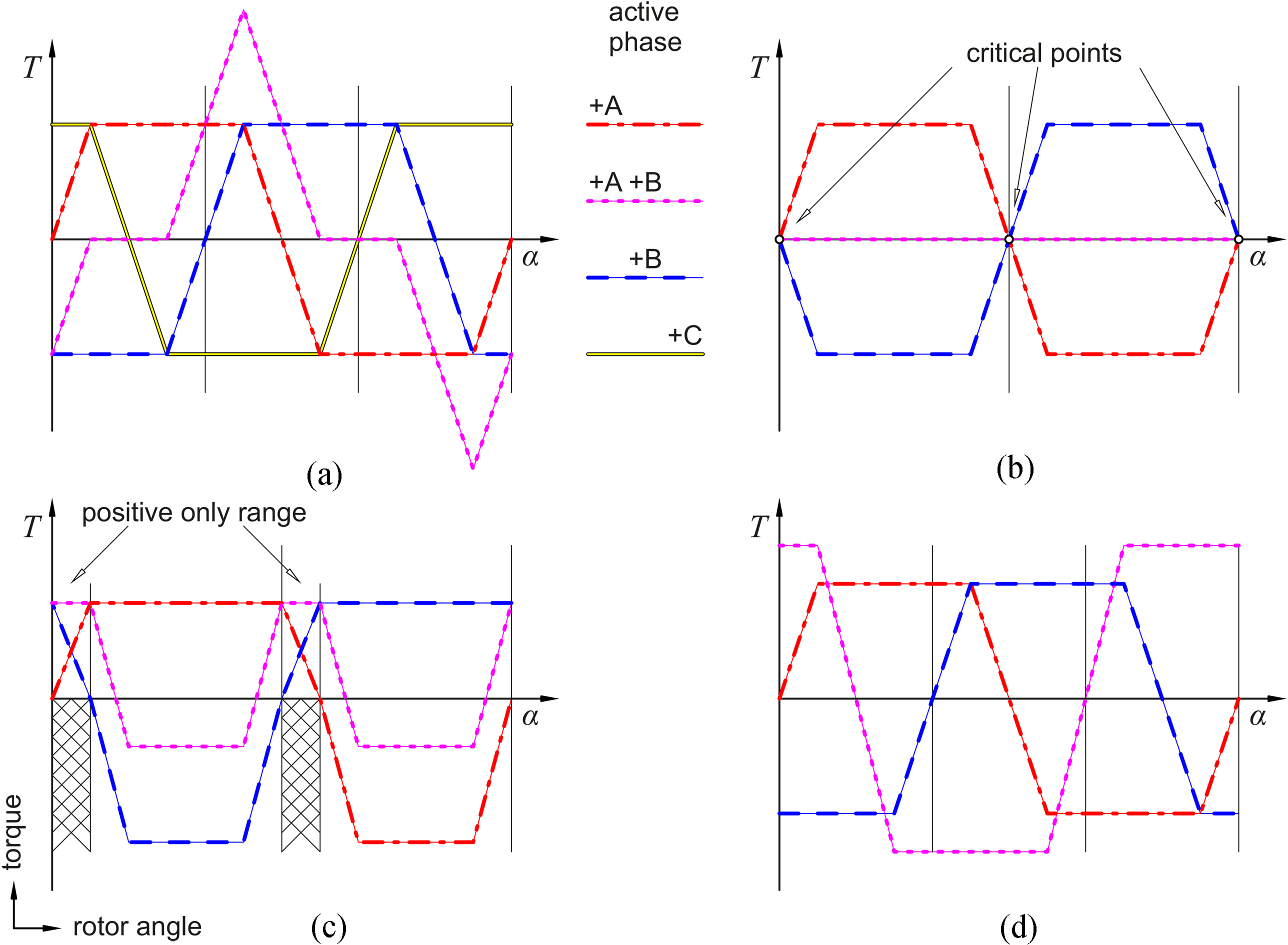
It seems that, due to symmetric current excitation, the three-phase MCSRM have decoupled torque characteristics, too. Recent two-phase machines use only two different torque characteristics as in Fig. 2b (symmetric) or Fig. 2c (asymmetric). Those figures here are only sketched. There are many detailed figures in [7, 10, 11].
When there are critical points at which the generated torque is smaller than the systems friction, then a motor with symmetric torque characteristics like in Fig. 2b cannot start on its own. Thus, many known two-phase SRMs use asymmetry to define a direction of rotation [7, 10, 11, 12, 13] or additional effectors (permanent magnets, auxiliary coils) to solve this self-start problem.
Note that simple superposition does not create more torque characteristics of the required type. For example, activating two phases A and B at once triggers both torque characteristics which are then added to a resulting torque characteristic +A +B that is usually between the two original torque characteristics (see Fig. 2a). This superposed characteristic is not a sufficient different one to be the required third characteristic.
Another disadvantage of a low phase number is high toque ripple. Some authors use more phases to overcome this [14]. Others use a more complex control like DITC [15, 16]. Having more torque characteristics than phases can help here.
There are also synchronous reluctance machines (SynRM) which use a rotating field and can operate with only two phases. They use three phases only because of the simple converter. But those machines are not described by torque characteristics relative to the stator frame. Instead, they use the rotating frame of the rotating field [17].
Some important SRM hardware components are electric power converter, a magnetic variable reluctance, and a mechanical rotor mass. The controller is usually implemented as software. Reluctance machine in this paper is only the magnetic subsystem and its overlapping states. Those states are electric current, magnetic flux and mechanical rotor position.
The rotor velocity controls the rotor position. With no mechanical load defined and the electro-magnetic dynamic being much faster than the mechanical, we assume the rotor velocity to be constant during an electro-magnetic period. Thus, the mechanical side is neglected and many quantities become functions of the rotor position.
With magnetic hysteresis and eddy currents neglected, current and flux are no longer independent. One current per phase is used here. A controller and electric power converter provide an electric voltage, which controls the current. More information can be found in books [2, 3]. We assume that the current is controlled well enough, so that the remaining error can be neglected. Thus, only the reference current at every rotor position remains to be considered.
Contribution to state of the art
The contribution to the state of the art is a partial inverse machine design method to derive a novel mutually coupled two-phase reluctance machine, that can produce more than two torque characteristics (in the stator reference frame). While the idea is not new [18], the inverse design helps to understand how it works. Such a MCSRM can be designed as sketched in Fig. 2d, if the mutual inductance and self inductance are utilized independent of each other. This allows low torque ripple, no block-switching during commutation and thus possibly less acoustic noise (pure harmonic current and voltage shapes as efficiency optimum), no self-start problem, but also includes disadvantages like a reduced efficiency.
The input phase currents and output torque can be identical to a rotating field synchronous machine (also compare to SynRM), while still using concentrated windings, salient poles, and no rotating field. These properties are derived theoretically based on the inductance, which is only well defined when ideal material with constant properties is assumed. The periodic structure required for this reluctance machine concept is independent of saturation, which must be considered only during optimization to obtain more accurate values. The presented equations can be modified to include the influence of saturation on the mean torque.
Section 2 outlines the inverse design, leading to the harmonic two-phase reluctance machine concept. Sections 3 and 4 analyze the performance of the machine and Sections 5.1 and 5.2 provide two example geometries with FEM results.
Machine design
The phase number is the first set parameter, still similar to common design methods. It is set to two in this paper, because it is the minimum number for a commutated machine. While the rotational form is used here for the description, all equations also apply to translation with large position range.
The first step in common design methods is to use parametrized geometry as input (e.g. saliency, pole angles, or iron thickness) [19, 20, 21, 22, 23, 24], which can be initialized based on the target torque and highly simplified equations. Accurate output quantities like inductance or torque are often calculated with FEM. During the optimization the geometry is modified until the output quantities satisfy desired criteria, e.g. maximum torque. In this direction the selected geometry parameters restrict the solution to a small space of possible geometries.
A complete inverse design is (today) impossible, because the number of possible geometry parameters is infinite (free form). But some steps can be done inverse. This splits the design into an inverse first part and a direct second part. Thus, only the second part of the design will be restricted by geometry parameter choice.
The first step in this partial inverse design method is the torque equation in the first part. This allows calculating the required reluctance characteristics for a desired torque characteristic of the machine. No geometry parameter set restricts the space of possible solutions at this point and the advantage is that new principles might be found.
The reluctance or permeance characteristics are an abstract theoretical description of the machine, like used in simulation models. Those characteristics have to be transformed into a geometry as a second part now. This is both, an advantage as well as a disadvantage. The whole space of possible solutions can be covered at this point. But finding a geometry that yields a specific characteristic is a difficult task, that is not completely solved in this paper. Solutions here have been found with manual iterative modifications of given geometries.
Working with characteristics requires a feasibility check to make sure resulting geometries are manufacture able. As the geometry does not exist during the first part of the partial inverse design, such a check can become a cascaded optimization itself.
Figure 3 summarizes both design methods. For common design the complexity reduces until a scalar to be maximized and the geometry (number of parameters) sets the complexity. In partial inverse design the complexity first increases into many possibilities and finally a high DoF-geometry is needed to produce the required characteristics.
Flow charts for the design methods. (a) Common design using reluctance 
The electric phase current is chosen as electro-magnetic state here because it is easier to measure. Controlling the current in each phase is often called commutation. It consists of three aspects: the distribution of current between the phases, the absolute power going into or out of the reluctance machine, and the periodic control over time as cyclic process.
The two phase currents
The angle
In common design the final current distribution and periodic control are set for optima like efficiency or torque ripple as very last step or even after the design part itself. With this partial inverse design method it is possible to include the commutation before a geometry is even defined. This allows exploring new possibilities on a more abstract basis, without the need to model geometries or even run experiments.
The torque
For a two-phase machine this yields
which contains partial derivatives of every inductance matrix element (
The length
The angle
Possibilities of combinations of phase current signs for a two-phase machine
Table 1 contains all angles
A reluctance machine can have infinite many different torque characteristics (one per current state, they are not linearly independent). Usually those are plotted, where the vector
For the special case Eq. (8), base shapes in
For
With only positive coefficients a positive value in the base shape can never become negative. The physical motivation behind this is the squared length
Not every superposition of base shapes is possible and they can be selected individually only for the special case Eq. (8). Only base shapes from current states next to each other in Table 1 can be combined (with positive sign). Other combinations trigger additional base shapes in coupled machines. Without the special case Eq. (8), linearly independent torque characteristics may each contain up to three base shapes at once in a mutually coupled reluctance machine.
The possible base shapes for a reluctance machine depend on the machine pole structure and to some extend also on saturation. To split up the torque characteristics into their shape and peak-peak-value, the effect of saturation on the base shape has to be neglected. Because saturation of the peak-peak value can be included by a non-quadratic scalar function
Overall, we can have four torque characteristics total with a bipolar two-phase machine (one base shape per inductance matrix element), or three torque characteristics with an unipolar machine. Such a solution does exist if we can set the self inductance independent of the mutual inductance. Using only self or only mutual inductance would be wasted potential.
Ideal machine characteristics
The special case Eq. (8) has the following advantages: only mutual inductance influence with two equal phase currents, only two base shapes apply at once, opposing use of self inductances to obtain both signs, gap-filling use of mutual inductance when changing from one self to the other self inductance during commutation (the change from one self directly to the other self is a problem, as shown in commutation example, Fig. 4c and d). It is the first restriction that reduces the solution space.
The second restriction is the choice of base shapes
The amplitude is set to
and those with both phases active are
with
The inductance representation itself is still independent of the magnetic circuit, which leaves many possibilities at this point to find new solutions. The solution presented here is a result of additional restrictions. Thus, there can be more possible solutions, also more coupled ones, or more symmetric ones.
Integrating Eq. (4) with
while
where inductance offsets
The total output torque from Eqs (4) to (7), (9), and (10) is
where
For a length
Commutation examples. (a) Torque coefficient and commutated angle 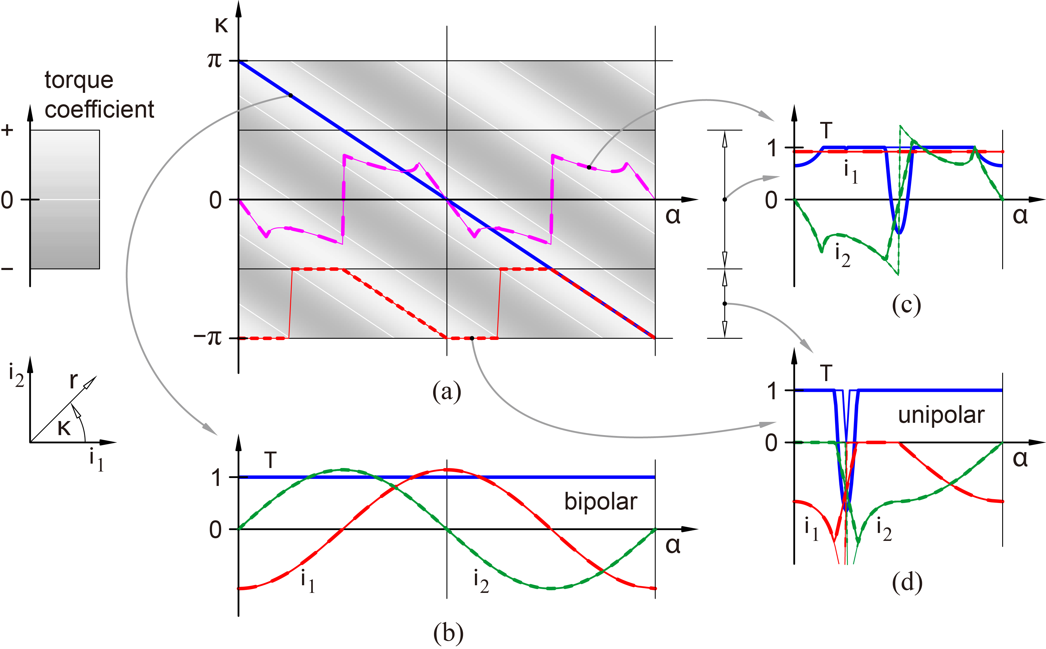
Every commutation is a line on the surface of the torque coefficient. The bipolar example Fig. 4b is chosen to maximize the torque while maintaining minimal copper losses, example Fig. 4d has bounded angles
The thick lines are a commutation for dynamic operation. Thus, in Fig. 4c and d there are short moments where both phases are active at once, which triggers the wrong torque characteristic leading not only to torque ripple, but also a negative torque peak. This problem can be resolved using the current sign symmetry and bipolar current supply, see Fig. 4b; or for restricted operation direction also with different inductance characteristics that work smooth with unipolar currents (not plotted).
From the desired torque or inductance, specific permeances can be calculated for any magnetic circuit. This reduces the coupled magnetic inductances to independent permeances, which are then easier to produce. The permeance is the inverse reluctance, but it is closer to the inductance.
For the magnetic domain (FEM or magnetic circuits), it can be easier to use the magnetic flux
This matrix contains permeances.
There are many magnetic circuits possible, e.g. depending on geometric restrictions. We now use the smallest possible magnetic circuit to provide the permeance characteristics for the harmonic two-phase reluctance machine example.
There are two possible smallest magnetic circuits: triangle and star, Fig. 5a. They have one reluctance/permeance for every independent inductance matrix element. Some flux examples for three different torque characteristics are sketched in Fig. 5b for both possible connections of those three points.
Triangle and star shapes. (a) Magnetic circuits. (b) Sketched flux (line thickness) to obtain three different torque characteristics.
While the three air gap reluctance characteristics might have a similar shape, they are still shifted differently along the rotor angle. This results in an asymmetric magnetic circuit. The reluctance characteristics with respect to the rotor angle are non-linear. From the circuits in Fig. 5a we derive the equations for both cases, where
Triangle:
Star:
Magnetic energy is stored in all three reluctances, but only supplied through two phases. That is why two rows are sufficient; the other would yield the remaining inner states.
For any positive reluctance the mutual inductance is always negative. The equations are given for the triangle only because those are shorter. They can be derived from Eqs (16) and (17) or Eq. (18).
Inductance offset parameters and comparison of derived quantities
Ideal characteristics and energy conversion. (a) Torque. (b) Inductance: self 
To ensure a positive reluctance, Eqs (20) or (21) yield an additional inequality. Assuming same phase winding numbers
The inductance offsets can be split up into constants and parameters
and the two self inductance characteristics, including Eq. (22) and harmonic base shapes, are
which all have the same positive amplitude
The required normalized (to maximum of triangle permeance) permeance characteristics are shown in Fig. 6c.
Some performance quantities can already be evaluated based on those inductances. For example, to obtain a small maximal flux (less iron volume needed, less iron losses) the ratio of the offsets hast to be near 1. This can be taken as an initial value for detailed optimization.
Especially the inductance offset in Eq. (24) is quite large compared to the inductance variation. That can result in much stored magnetic energy during the operation cycles: energy that is not transformed into mechanical work.
To get more insight into the energy conversion, the determining field quantities magnetic flux and magneto motive force (MMF) for bipolar current supply are plotted in Fig. 6d. An area surrounded by one of those lines equals the transformed energy per periodic cycle. The thin lines that pass the center point correspond to each reluctance of the triangle or star shaped magnetic circuit. These all are passed counter clock wise, which means they all transform magnetic energy into mechanical.
The determining lines are the red and green cycles that do not pass the center point. The red one is the MMF generated by, and the magnetic flux passing through phase A. It is also counter clock wise, and generates mechanical work. But the green cycle of phase B is passed clock wise. That means it uses magnetic energy and transforms it into electrical energy at phase B. Thus, while there is energy flowing into one phase, a part of it will come back out of the other phase. The mechanical work done during one cycle is the difference between the red line surrounded area and the green line surrounded area. Table 2 shows the power ratio (active power to input power) that is converted into mechanical output power (active power), while the remainder is returned as electrical output power. This is a result of the mutual coupling in the magnetic circuit. The power factor is the ratio of active power to apparent power and the saliency ratio relates the aligned permeance to the unaligned permeance. Additionally, Table 2 compares to the SRM shown in Fig. 1a, where some values depend primarily on the current shape, but also the rotation speed.
Finding a geometry
The iron geometry is used to produce the required permeance characteristics. The high amount of possible geometry parameters provides a huge space for solutions, and thus a high chance that a solution exist, but finding an optimum is even more difficult. An additional condition is that saturation should occur at once all over the whole machine, which yields a reference for the iron cross-section areas. Winding area is estimated to cause no more than
The central node in the star shaped magnetic circuit can be the rotor. In that way every reluctance is mapped directly to one airgap. The following designs have been found manually. Therefor, the inductance offsets are set very high (see Table 2), which makes it easier to find a solution. While the designs do work, note that they are not optimized at all. The first row in Table 2 compares to the theoretical upper limit reference.
2D-design
For a radial flux machine two stator periods are used to compensate radial forces. This results in the same magnetic circuit as a three-phase MCSRM. The third phase can be omitted, if correct reluctance characteristics are used. With only two phases it becomes similar to the E-core SRM [13]. But latter reduces the mutual coupling with a wider stator pole and still uses asymmetric rotor poles to define a direction of rotation. This shows how important the reluctance characteristics are.
Figure 7 shows the 2D-machine. The correlation between reluctance and airgap is marked in Fig. 7b. Figure 7a contains the torque characteristics at different loads and Fig. 7c some magnetic field shapes during commutation. All torque characteristics have a reduced peak-peak value when the machine saturates at 2000 A (excitation in each coil, two coils per phase).
Manually guessed radial flux machine. (a) FEM calculated torque characteristics for a 2D-design. (b) 2D Geometry. (c) Magnetic flux lines for a sequence of aligned rotor positions during commutation.
Figure 8b shows a transversal flux machine. The torque is calculated while the outer rotor poles are rotated ccw in small steps to obtain the torque characteristic of a at different MMF excitations. While 500 A and 1000 A are before saturation in the iron, 2000 A saturates the machine, resulting in lower peak-peak-values. Only one characteristic has no saturation yet, due to shorter flux path.
Manually guessed transversal flux machine. (a) FEM calculated torque characteristics for a 3D-design. (b) 3D Geometry. (c) Sketched flux lines during commutation (aligned positions) on flux density (color).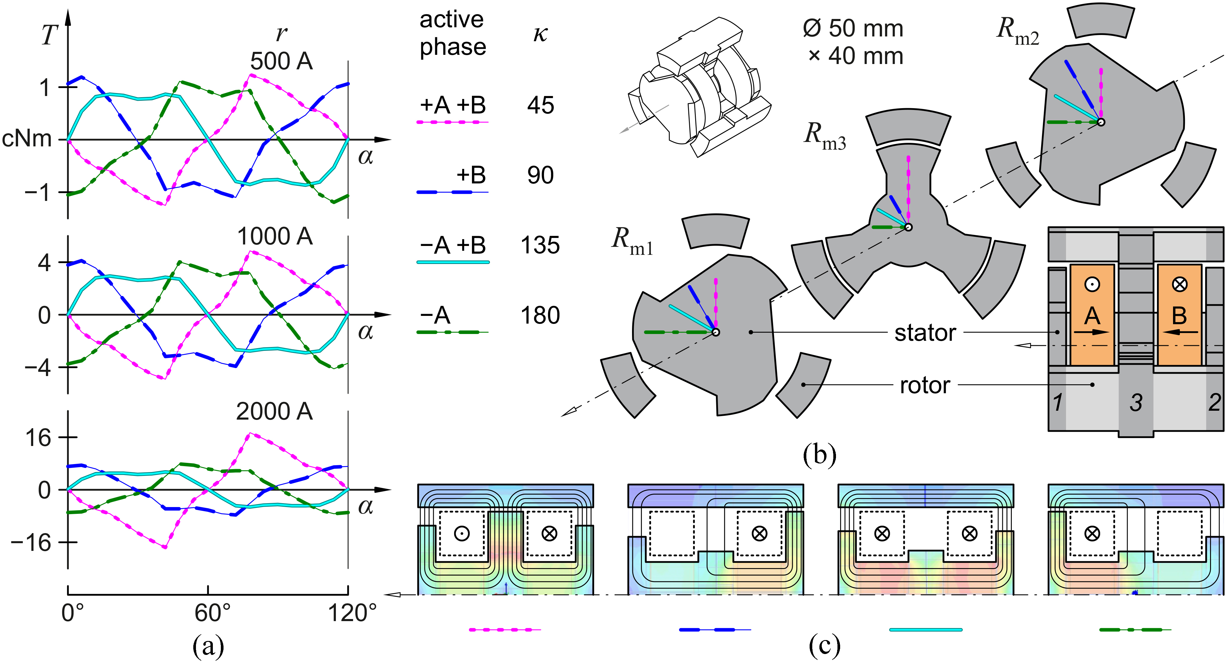
The flux lines in Fig. 8c are only sketched based on the magnetic flux density. This commutation sequence shows the aligned states, the zero crossings of the corresponding torque characteristics with negative slope. The cut-plane follows the upper rotor pole. For every rotor angle, there is a torque characteristic with positive and one with negative values that are non-zero. Thus, the machine can generate a bidirectional torque at every rotor position.
For a short comparison different aspects can be found in Figs 7 and 8. Both torque characteristics sets are similar to the desired ones from Eqs (11) and (12). Linear magnetic circuit model and non-linear FEM calculations agree about the feasibility of the harmonic two-phase reluctance machine concept. Also, note the quadratic relation with the length
Conclusion
It is possible to build a two-phase reluctance machine that can generate a torque at every rotor angle position in both rotation directions. Thus, a partial inverse design can explain a different solution to the self-start problem of two-phase motors. Such a design direction shows many sideways and a huge space for more possible solutions, which can have a very simple construction but still superior performance similar to rotating field machines like the synchronous reluctance machine. There is much less torque ripple and possibly less acoustic noise. However, due to the concentrated windings and salient poles there is no homogeneous rotating field.
The harmonic two-phase reluctance machine has restrictions in the commutation because a superposition of torque characteristics of single phases is no longer valid in every case. Some problems here can be solved with bipolar current supply. There are always two airgaps in a row, which never have minimal value at once. Thus overall, the airgap is quite large, which indicates reduced efficiency. The machines reactive power is at least 50% of the mechanical power.
Pole shaping becomes important here, as a given reluctance characteristic has to be developed into machine pole geometry. That was not addressed in this paper. This mutually coupled reluctance machine operation with two phases highly depends on the reluctance characteristics.