
Abstract
The rotor attitude detection of spherical motors usually requires the installation of position sensors on the rotor shaft or stator to achieve, which occupy a large space and cause negative effects for the practical installation and application of spherical motors. In this paper, a sensorless position detection method for reluctance spherical motors based on the structure and operating characteristics of reluctance spherical motors is proposed. By detecting the stator coil inductance data at different rotor attitude angles, the position prediction model is constructed using the extreme learning machine algorithm. Through comparison and validation, it is demonstrated that the rotor attitude angle obtained by the method is highly accurate, providing a feasible idea for the control and application of reluctance spherical motors.
Introduction
As the modern manufacturing industry gradually develops in the direction of automation and intelligence, the demand for actuators can realize three degrees-of-freedom (3-DOF) movement. Traditional 3-DOF movement actuators are coupled with multiple single-degree-of-freedom motors and transmission mechanisms, which still have complex structures, poor interference resistance and control difficulties. At present, experts and scholars in the world are increasingly inclined to use 3-DOF spherical motors instead of the above-mentioned actuators in order to solve these problems [1,2]. As a result, the importance of research on motion control and rotor position detection of spherical motors is gradually increasing.
At present, most of the spherical motors developed by universities and research institutes are permanent magnet spherical motors, which have the inherent advantages of flexible movement, simple structure, small torque ripple, small starting current, etc. But its disadvantages are also obvious, such as low output efficiency and limited output torque. And because a large number of permanent magnets are installed in the rotor, it is large in volume, high in cost and difficult to control. In order to solve these problems, a reluctance spherical motor 3 is proposed [3]. The reluctance spherical motor is designed on the basis of switched reluctance motor, which adopts double convex structure and rotates the rotor according to the principle of minimum reluctance. The reluctance spherical motor contains a core without permanent magnet, and only the stator part contains an active coil, which simplifies the structure of the motor and reduces the complexity of the control system. Compared with permanent magnet spherical motor, the output torque is increased.
There are two main types of spherical motor rotor position detection methods: contact and non-contact. The contact methods require sensors to be mounted on the output shaft, such as the detection methods used in [4–6]. Although these methods are more accurate, they interfere too much with the motion of the ball machine and can have a significant impact on the output torque. These disadvantages can be avoided by using the non-contact methods, such as the works in [7,8], which utilise the induced voltage in the stator coil of a permanent magnet spherical motor to achieve sensorless position detection. A machine vision method is used to detect the rotor position [9], but this method requires more space and is slower. A fibre optic sensor is used to capture the reflected light to detect the rotor position [10]. A laser detector is used to measure the distance from the target to the detector on several photoelectricity to calculate the angle of deflection of the rotor in three directions [11]. What the above methods have in common is that they all require position sensors to be installed on the rotor or stator to achieve this. These sensors take up a large amount of space, which has a negative impact on the practical installation and application of spherical motors.
In this paper, the structure and motion characteristics of reluctance spherical motor are studied, and the rotor position detection of specific multi degree of freedom motion trajectory is realized. In the process of online rotor position detection, a machine learning algorithm is used to predict the three-dimensional position angle of the rotor based on the inductive information collected in real time. Using the reluctance spherical motor proposed in [3] as the research object, the effectiveness of this sensorless position detection method is verified by building a sample database and comparing the results of the actual angle with the predicted angle.
Introduction to reluctance spherical motor
The structure of the reluctance spherical motor studied in this paper is shown in Figure 1. The stator coil is divided into upper, middle and lower layers, with 8 evenly distributed in each layer, and the latitude angle between stator phases is 33°. The motion of reluctance spherical motor can be decomposed into the synthesis of spin motion and tilt motion with two degrees of freedom. The two motions are based on the principle of minimum reluctance. When the excitation is generated in the stator coil, the magnetic line of force will flow towards the salient pole of the rotor, generating a tangential magnetic pull, which makes the rotor rotate under the force. By controlling the combination and mode of energizing the stator coil, the reluctance spherical motor can complete a three degree of freedom movement.
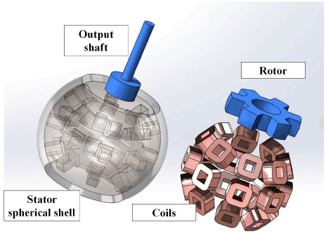
Schematic diagram of the structure of a reluctance spherical motor.
Based on a basic kinematic perspective, a study of the motion of a reluctance spherical motor must first determine the basic reference coordinate system. Since a reluctance spherical motor consists of two main components, the stator and the rotor, two coordinate systems are established in this paper: the stator coordinate system and the rotor coordinate system as shown in Fig. 2.
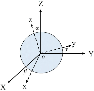
Schematic diagram of the two coordinate systems.
The solid line shows the stator coordinate system and the dotted line shows the rotor coordinate system. The origin of these two coordinate systems coincide, which is the inner ball center of the stator spherical shell. The stator coordinate system is a fixed coordinate system with the z-axis vertical upwards, perpendicular to the equatorial plane, and its relative position does not change with the movement of the spherical motor. The z-axis of the rotor co-ordinate system coincides with the output axis of the rotor and specifies the direction of x and y axis along a given rotor tooth as the ox ray. The rotor coordinate system is a kinematic coordinate system, whose relative position changes with the motion of the rotor.
These two coordinate systems have the same origin and, by default, are initially coincident. During the motion of the spherical motor, the rotor coordinate system is offset from the stator coordinate system. As mentioned above, this offset can be considered as a superposition of three single-degree-of freedom rotations, and the angle of offset resulting from each rotational motion is the Euler angle. This paper uses a set of Euler angles 𝜒 = [𝛼 𝛽 𝛾] T rotated in the stator coordinate system to represent the relative positions of the rotor coordinate system in the order of rotation about the X, Y and Z axes, respectively, with the default counterclockwise direction being positive.
If the rotor coordinate system is rotated by an angle of 𝛼 about the X-axis of the stator coordinate system, the basic rotation matrix can be obtained as follows:
Similarly, when the rotor coordinate system is rotated around the Y and Z axes of the stator coordinate system by angles 𝛽 and 𝛾, respectively, there are basic rotation matrices:
The rotor coordinate system is rotated three times in the above order, i.e. the three matrices above are multiplied to the left to achieve the angular conversion of the two coordinate systems as expressed below,
s (x) and c (x) in this matrix expression represent trigonometric functions sin(x) and cos(x) respectively. For any point P = [p
x
p
y
p
z
]
T
in the rotor coordinate system in the initial default state, its new position vector P
′
with respect to the stator coordinate system after the motion of the spherical motor is:
If only the eight stator coils on the equatorial line of the stator spherical housing are considered, the reluctance spherical motor can be seen as an ordinary switched reluctance motor; if only the three stator coils on the same longitude. are considered, the reluctance spherical motor can be seen as part of a switched reluctance motor. Thus, the reluctance spherical motor has two most important basic types of motion: spin motion and pitch motion, which are shown schematically in Fig. 3.
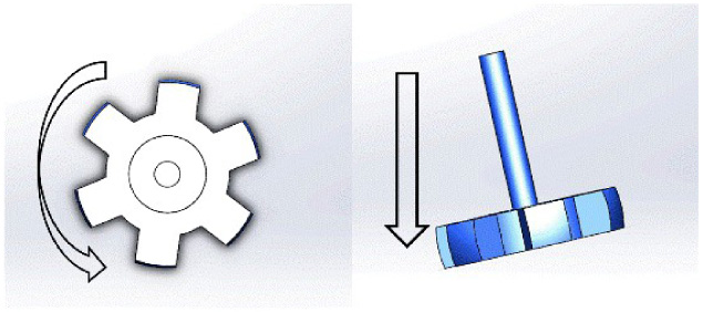
Schematic diagram of rotational and inclined motion.
When a reluctance spherical motor is in spin motion, the principle of motion is similar to that of a switched reluctance motor. The eight stator coils located on the equatorial line provide excitation current according to a certain charging strategy to generate magnetic lines of force in the air gap as the magnetic flux always flows along the magnetic lines of least resistance, a magnetic pull is generated which causes the rotor teeth to rotate. The principle of tilting motion is similar, except that the currents are applied to three stator coils located at the same longitude.
In addition to the above two types of motion, there exists a typical motion which is a combination of above two types of motion. The rotor makes a rotational motion on the basis of a certain angle of inclination, and its motion is shown schematically in Fig. 4. The position of the rotor motion can be indicated by the angle of inclination 𝛽 and 𝛾 in the stator coordinate system.
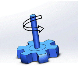
Schematic diagram of the combined movement.
In the research of sensorless position of switched reluctance motor, a method of rotor position detection based on induction characteristics is proposed. For reluctance spherical motors, the ability to achieve 3-DOF movement results in a large variation of the inductive characteristics. Therefore, in order to realise sensorless rotor position detection under complex movement, it is necessary to build an experimental platform to test the inductance of the stator coil of a reluctance spherical motor and obtain the inductance characteristics under different modes of motion for further analysis and research.
Inductance testing methods
In order to obtain the numerical relationship between rotor deflection angle and coil inductance, a test experiment platform is designed in this paper, as shown in Fig. 5. It consists of a reluctance spherical motor to be tested, an STM32F4-based data acquisition and processing module, a power amplifier circuit, an inductance detection circuit and a contact position detection bench.
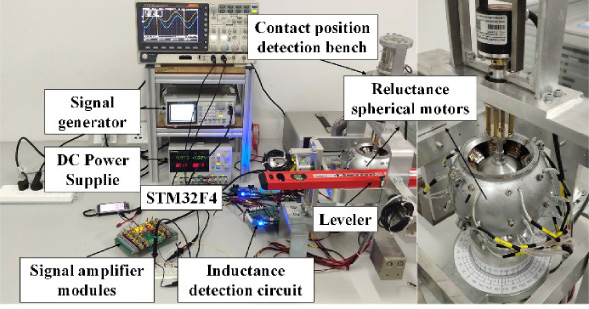
The experimental platform of the Reluctance spherical motor.
The contact position detection bench uses an optical encoder to record the actual angle of the rotor for subsequent predictive modelling and accuracy checks. The STM32F4 is used for data acquisition and processing. Due to the load limitations of the signal generator, a signal amplifier module is added to stabilize the detection signal amplitude.
Existing inductance/chain measurement methods for single-DOF switched reluctance motors are based on the characteristic of periodic motion driven by a single-DOF motor-loaded AC current. However, because the reluctance spherical motors are driven by DC current and have a complex and variable motion, they are capable of 3-DOF movement and their movement is non-periodic, which makes the previous inductance/chain measurement methods for single- DOF rotary motors not directly applicable to inductance/chain measurement of 3-DOF reluctance spherical motors. Therefore, there is an urgent need for an inductance/chain measurement method for 3-DOF reluctance spherical motors.
In order to measure the inductance of a stator coil at any rotor angle in a reluctance spherical motor, an impedance-based inductance detection circuit is designed and built, in which a signal generator and a power amplifier circuit are used to provide a sinusoidal waveform with a stable frequency and amplitude. The inductance detection circuit is based on the impedance method, which indirectly calculates the final stator coil inductance by attaching a standard resistance to the stator coil of a magneto-resistive spherical motor and measuring its partial voltage. The schematic diagram of the inductance detection circuit and the partial voltage vector diagram of each part of the impedance device are shown in Fig. 6.
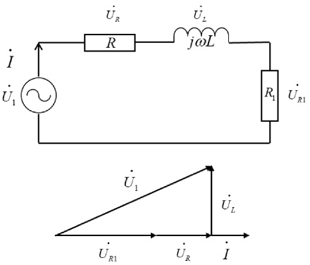
Schematic diagram of the inductance detection circuit and the voltage division vectors for each part of the impedance device.
The specific steps of the inductance measurement are described below. The signal generator generates a fixed frequency AC sine wave, which is amplified by a signal amplifier circuit to increase the amplitude and eliminate spurious interference, providing a stable detection signal for the inductance measurement circuit. The STM32F4 is used to detect and record the total input voltage of the circuit at this point,
Since the partial voltages on the resistors are all in phase, the partial voltage
The sum of the two is the partial voltage
Finally, according to the impedance formula:
The magnitude of the circuit
Based on the above analysis, a reluctance spherical motor experimental platform as shown in Fig. 5 was built to obtain twelve sets of stator coil inductance data under different complex movement modes.
The inductance of each of the 12 stator coils of the reluctance spherical motor varies during different movements, so it is necessary to number the 12 coils in order to analyze the inductance of the different coils during movement. Firstly, the rotor teeth are aligned with one of the stator coils on the equatorial line in the absence of pitching motion, and this stator coil group is designated as coil group 1. The upper and lower coils are also calibrated in the same way and are numbered as shown in Fig. 7.
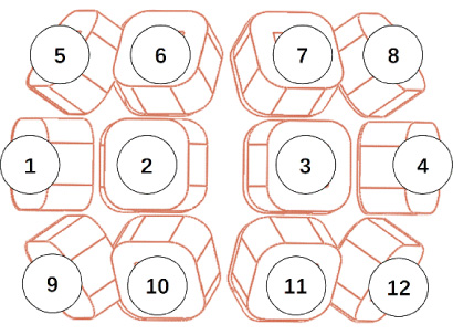
Schematic diagram of numbering of the reluctance spherical motor coil set.
After the establishment of the experimental platform, in order to verify the reliability of the inductance measurement results, coils 1 was selected to measure at the Angle of 0 ∼ 30 during the spin movement. The inductance data measured on the experimental platform was compared with the finite element simulation data, and the results were shown in Fig. 8.
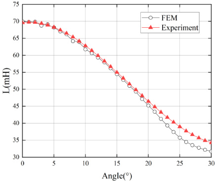
Comparison between experimental measurement and finite element simulation.
It can be seen from the comparison results that the variation trend of the experimental measurement results and the finite element results is the same. When the rotor teeth and stator are near the alignment position, that is, when the spin Angle is close to 0, the two results are consistent. After the demand is gradually increasing the distance between the rotor and stator, the gap will gradually appear in small increments This error may be the motor prototype in the assembly process of gas gap is not uniform, the stator coil their size is too big, causing the deviation on the structural parameters, such error is in the acceptable range, proving the validity and reliability of the measuring methods of the inductance.
The inductance characteristic curves of the 12 sets of coils of the reluctance spherical motor during the spin motion in the range of 0° to 360° and the pitch motion in the range of −30° to 30° were measured experimentally and are shown in Figs 9 and 10.

Inductance characteristics of spin motion.

Inductance characteristics of pitch motion.
As can be seen from the inductance characteristics diagram, during the spin motion of the reluctance spherical motor, the inductance of the four groups of coils from 1 to 4 at the equator varies with the rotation angle with a period of 60° in the form of a sine wave, and there is a 15° phase difference between the inductance characteristics curve of each group of coils, while the inductance of the eight groups of coils from 5 to 12 at the upper and lower sides is smaller and remains basically unchanged.
The pitch angle 𝛽 of the reluctance spherical motor ranges from 0° to 30°. So, the pitch angle is first set to 15° to detect the inductance on the 12 sets of stator coils during the rotor 𝛾 angle rotation of one periodicity from 0° to 360°, and the inductance characteristics obtained are shown in Fig. 11.

Inductance characteristics versus the spin angle at an inclination of 15°.
As can be seen from the first diagram, for the four stator coils on the equatorial line, the inductance varies with a period of 180° and a phase difference of 45° between each coil, with a variation pattern similar to that of a sine wave. Due to the effect of pitched motion, the relative distances between the rotor teeth and the stator coils when they coincide in longitude may be different due to the effect of latitude, so each peak in the characteristic waveform of the inductance of the same coil is not the same.
The second and third diagrams show the inductance characteristics of the eight sets of coils located at the top and bottom with a 360° inductance variation period and a phase difference of 45° between each coil. The corresponding inductance rises to a large value only when the rotor teeth are close to the stator coils, and the rest of the angles are maintained at smaller fixed values.
From the above analysis, it can be seen that the inductance characteristics of the 12 groups of coils in the process of combined motion of the reluctance spherical motor are most representative of the inductance characteristics of the first and fifth groups of coils.
Changing the pitch angle 𝛽 to 5° versus 25°, the inductance on the stator coils of groups 1 and 5 during a rotor rotation of 0° to 360° was measured and the inductance characteristics obtained are shown in Fig. 12.
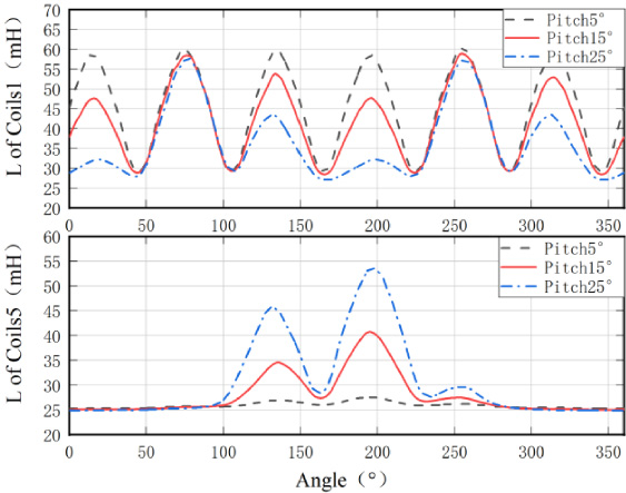
Inductance characteristics at different pitch angles.
As can be seen from the graph above, for coil group 1, the inductance characteristic curve gradually decreases as the pitch angle increases, with less decrease near the rotor tooth crest position closest to the stator coil and more decrease at the crest position relatively far away. For coil group 5, the inductance curve gradually rises as the angle of inclination increases, and the magnitude of the change increases. This is because the coils in groups 1 and 5 are located at 0° and 30° of rotor tilt angle 𝛽 respectively. Therefore, as the pitch angle of the rotor teeth increases, it gradually moves away from and closer to these two groups of coils, and the corresponding changes in their inductance characteristics decrease and increase.
By analyzing the inductance characteristics of the reluctance spherical motor, it can be seen that there is an obvious linear relationship between the inductance and the angle on the 12 sets of stator coils of the reluctance spherical motor under different modes of motion. Considering the high dimensionality of the input data, a machine learning algorithm, the Extreme Learning Machine (ELM), is selected in this paper to build up a regression prediction model between the 12 sets of inductance data and the 3-DOF angle.
Basic principles of ELM
The core idea is to achieve classification or regression of the training set by continuously optimizing the weights and deviations within the trained neural network, which is prone to the problem of long iterative training process and limited to local optimum. Therefore, a new single hidden layer feedforward neural network, the Extreme Learning Machine (ELM), was proposed.
The fundamental difference between ELM and other algorithms is that the hidden layer parameters are generated arbitrarily in ELM, so that the hidden layer nodes can be created before the training set data is input, and the weights of the output layer are calculated by the inverse matrix, which greatly improves the training speed of the model [10–17].
The basic structure of the ELM is similar to that of a traditional single hidden layer feedforward neural network, as shown in Fig. 13.

Basic structure of ELM.
In this figure, h (x) represents the hidden layer function whose output is a nonlinear activation function g (z) where z is the input x times the weight value ω plus the deviation value b, as expressed below
During the design and implementation of the ELM, there are various choices of activation functions, such as Sigmoid functions, Gaussian functions, etc.
There is also an output weight δ between the hidden layer and the output layer by using the output layer function of the ELM can be obtained as
The above analysis shows that the training process of the ELM is the process of determining the hidden layer weight value ω, the deviation value b and the output layer weight value δ. It is mainly divided into two parts: randomly setting the hidden layer parameters and solving the output layer parameters.
The biggest difference between the ELM and other neural network algorithms is that its hidden layer parameters ω and b are generated randomly, so the training speed in the first stage is greatly improved. The subsequent work is to find an optimal δ that gives the highest accuracy of the regression model.
Set the minimized squared difference between the output function of the neural network and the sample labels as the training objective, i.e:
The optimal solution of Eq. (11) is
H
† is the generalized inverse matrix of H, which can be calculated by the orthogonal projection method as follows:
At this point, the hidden layer weight value ω, the deviation value b and the output layer weight value δ have all been determined, and the construction of the regression model has been initially completed.
As mentioned in the previous section, the implied layer parameters ω and b of the ELM are generated randomly, which can reduce the stability of the model. To improve this problem, a regularization factor C and a radial basis kernel function 𝛺
ELM
= exp(−∥x
i
− x
j
∥2∕2σ2) can be introduced, and the output function is:
The PSO algorithm is inspired by the mimicry of a flock of birds foraging for food. The core idea is to consider both the individual optimal solution and the population optimal solution, both of which affect the selection of the position and velocity of the particles in the next iteration, with the advantages of simplicity, speedup and the fact that it does not easily fall into local optima.
The overall modelling process of an ELM based on PSO is given in Fig. 14.

ELM based on PSO.
Due to the large amount of data for the three angle combinations, this paper chose to conduct validation tests within a specific range of variation: −5 to 5° for 𝛼, −20 to −10° for 𝛽 and 10 to 20° for 𝛾. Within this range, 12 sets of coil inductances corresponding to different angle combinations were recorded. The recorded data samples were divided into a training set and a test set.
The 12 sets of coil inductances from the training set were used as input and the actual 3-DOF angles were used as output to construct the ELM model and optimize the parameters by using PSO.
After the ELM model was trained, the 12 sets of coil inductors from the test set were fed into the model and the predicted angles were compared with the actual angles, the results are shown in Fig. 15.
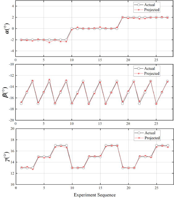
Result of experiment.
From the results, the ELM regression prediction model based on PSO fits all three angles 𝛼, 𝛽 and 𝛾 better and the possible reasons for the errors are as follows. Deviations from the inconsistent magnetic circuit due to the manufacturing process and assembly accuracy of the spherical motor. The angle detector used to determine the actual attitude angle of the rotor showed a slight deviation in the correction. In order to improve the speed of model training, the number of iterations of the PSO algorithm is strictly limited, leaving room for further improvement in the accuracy of the model.
To address the position detection problem of spherical motors in 3-DOF movement, a sensorless position detection method based on ELM for spherical motors is proposed. The most significant advantage of this method is that it does not require the installation of position sensors on the body structure of the spherical motor, which greatly reduces the space required for the actual installation and application of the spherical motor, enhances the overall stability of the system. Experiments prove that the model has high accuracy in angle prediction in all 3-DOF directions and can be used to help spherical motors escape the influence of traditional position sensors on the output torque. The paper verifies the feasibility of the sensorless position detection method of spherical motor based on ELM. In order to provide important support for real-time control of reluctance spherical motor, it is necessary to further improve the detection accuracy, and simplify the detection circuit and algorithm to speed up the detection.
Footnotes
Acknowledgements
This work was supported by the Key Project of the China National Natural Science Foundation under Grant No.51637001, and the Nature Science Research Project of Anhui province (1908085ME168).
Data availability
The data that support the findings of this study are available from the corresponding author upon reasonable request.