
Abstract
This paper presents a novel double-magnetic-source magnetic circuit (DMSMC) with pole shoes (PS) in order to achieve high and uniform air-gap magnetic field in an angular vibration exciter. First, the structure of the DMSMC with PS is proposed based on the demand of the angular displacement of 60
Introduction
Angular vibration exciters are widely applied in the area of environmental vibration tests for variety of products, dynamic characteristic tests for the inertial navigation systems such as gyroscopes, and angular calibration system for different angular vibration transducers [1, 2, 3, 4]. In order to meet the demand mentioned above, angular vibration exciters should output stable and low distortion torsional vibration, especially in the angular vibration calibration system.
In general, electromagnetic angular vibration exciters are suitable to produce high quality angular displacement, angular velocity and angular acceleration because of their rapid response, easy accessibility and high linearity. Ordinary rotating motors are typical electromagnetic angular motion generators, which could output rotating motion and have widely been applied in the power rotation machinery [5, 6, 7]. But due to their slot effect, electromagnetic attractive force, harmonics of the back electromotive force (EMF), saturation of magnetic circuit, lower torsional inherent frequency of the rotor, etc. [8, 9, 10], they are always not suitable to use for high-precision and high-frequency angular vibration exciters.
A disk-type motor is a specially-designed motor, whose rotor is a disk-shape coil and stator is a group of permanent magnets. The motor could work with high efficiency and the output torque is high and smooth because there is less iron loss and no slot effect. In view of the features of the disk-type motor with high magnetic field intensity and power density [11, 12, 13, 14], an axial flux magnetic circuit structure with disk-shape coil was recommended in the ISO 16063: 2006 standard for a standard angular vibration exciter [4], but how to design the magnetic circuit of angular vibration exciters has not been studied in detailed. For the disk-type motor, many attentions have been paid on high output torque, stable rotation, high efficiency, low cost, convenient, etc. So multi-pair of permanent magnet has been designed, but few attentions have been paid on the fringe effect of permanent magnet and the uniformity in the air gap, which results in the nonlinearity of the exciter and the distortion of the output from the exciter. So it is necessary to improve the magnetic circuit structure to meet the demand of larger angular displacement and low-distortion angular acceleration for electromagnetic angular vibration exciters. In this paper, a double-magnetic-source magnetic circuit (DMSMC) with pole shoes (PS) is proposed, which has high and uniform magnetic flux density (MFD) in the air-gap.
Magnetic circuit structure of the exciter
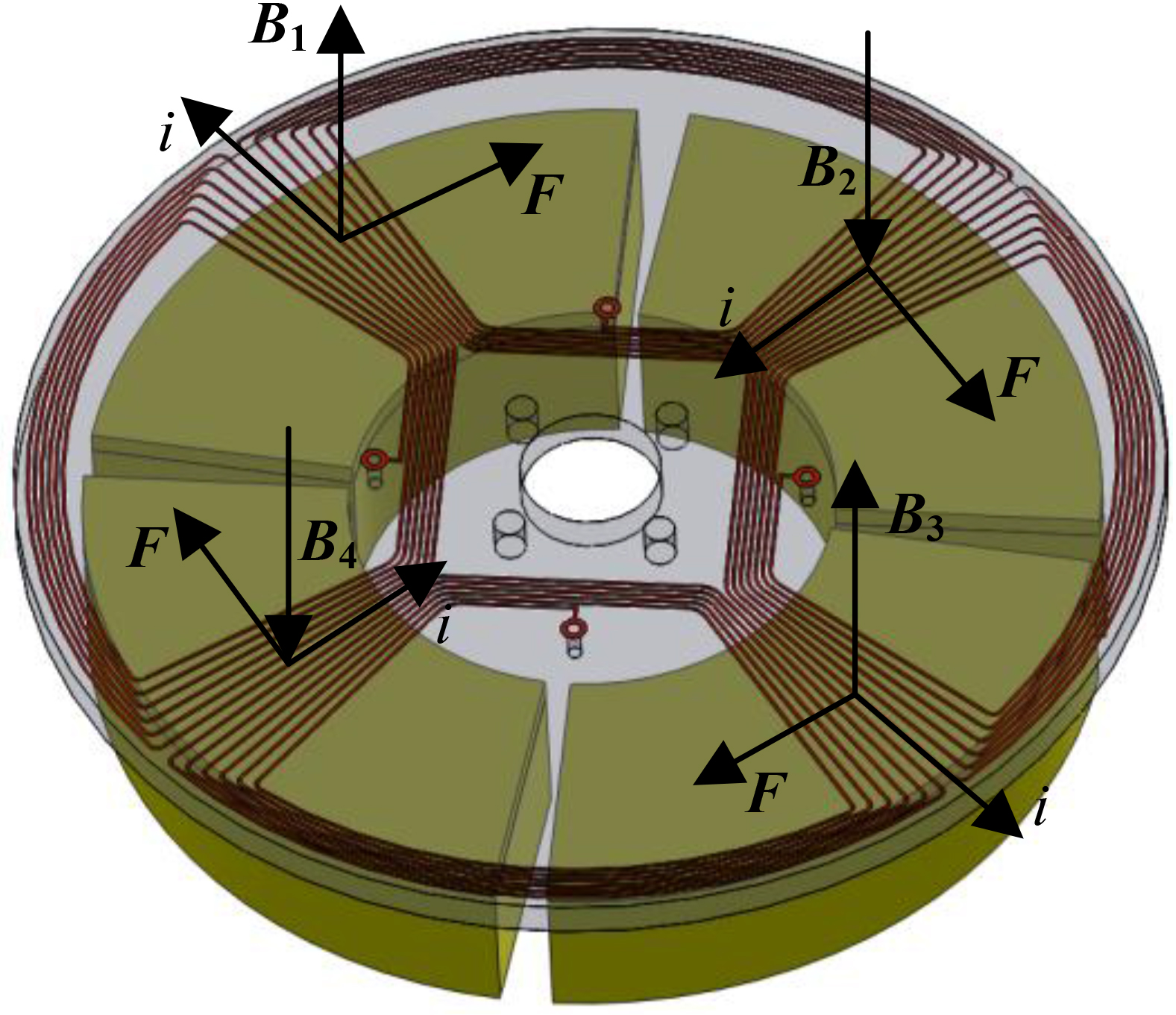
The structure diagram of designed electromagnetic angular vibration exciter is shown in Fig. 2, which consists of a closed magnetic circuit, an air bearing, a disk moving component, etc. Especially, the disk moving component mainly comprises a vibration table, a connecting shaft and a disk moving coil. The disk moving coil is located in the axial air-gap magnetic field of a closed magnetic circuit. The principle of the exciter is based on the Lorentz force law, which is simply described that a current-carrying conductor placed in a constant magnetic field will be acted by an electromagnetic force.
Structure diagram of the exciter. Schematic diagram of the exciter.
DMSMC with PS.
As shown in Fig. 2, four permanent magnets on the same plane are adopted in order to meet the demand of the angular displacement of 60
Based on the above principle of the exciter, the magnetic field should be designed to be strong and uniform enough to get large and low-distortion angular acceleration. Considering this key issue, a double-magnetic-source magnetic circuit (DMSMC) with pole shoes (PS) is proposed as shown in Fig. 3, in which the magnetic circuit consists of the upper magnetizer, the upper permanent magnet, the upper PS, the lower PS, the lower permanent magnet, the lower magnetizer, the magnetizer ring and the air-gap. To realize the superposition of the magnetomotive force in the air-gap, the magnetic flux of the upper and lower permanent magnet should be connected in series, and the magnetization direction of the upper permanent magnet and the lower permanent magnet is identical.
Double-magnetic-source magnetic circuit
The equivalent circuit method is applied to analyze distribution characteristics of the air-gap magnetic field. Suppose that the magnetic circuit is not saturated, and the leakage flux is neglected, and the reluctance of PS is so small that they could be neglected.
To conduct the theory analysis, the lumped parameters of the magnetic circuit are adopted. The upper and lower permanent magnet are equivalent to the magnetomotive force
Equivalent model of the DMSMC. Magnetic flux refraction.
The magnetic voltage drop equation can be obtained based on Kirchhoff’s voltage law, that is
Because of the symmetry of the geometric parameters and the magnetic characteristic parameters of the upper and lower permanent magnet, the magnetomotive force and the magnetic voltage drop of the upper permanent magnet are equal to those of the lower permanent magnet. Considering the basic equation of magnetic circuits, the expression of the magnetomotive force and the magnetic voltage drop can be written as
where
The expression of the magnetic voltage drop in the air-gap and the magnetic voltage drop in the magnetizer can be found as
where
Meanwhile, if there is only one magnet in the magnetic circuit, that is
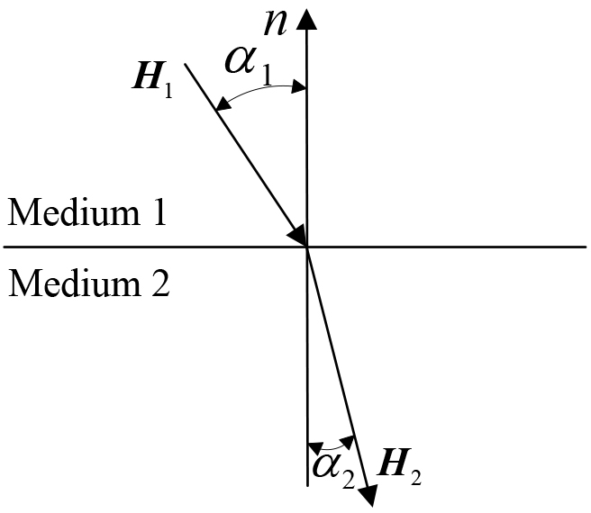
The path of the magnetic flux will be changed in the interface of the medium with different magnetic permeability, whose phenomenon of the magnetic flux refraction is shown in Fig. 5.
Magnetic line in the air-gap. (a) Permanent magnet without PS. (b) Permanent magnet with PS. A pair of permanent magnet with PS.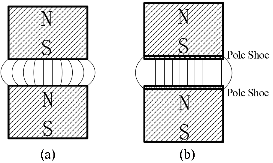

When there does not exist the current that passes through the two sides of interface, the expression of magnetic flux refraction on the interface can be written as [15]
or
where
From Eq. (6), it could be found that when the magnetic flux passes through the interface from the medium with high permeability to the medium with low permeability, the magnetic line will become much more perpendicular to the interface. Especially, if
The magnetic lines produced by the permanent magnet without and with PS in the air-gap are shown in Fig. 7. For the permanent magnet without PS, the directions of the magnetic lines remain almost unchanged on the interface between the permanent magnet and the air-gap since the permeability of the permanent magnet is close to that of the air-gap. For the permanent magnet with PS, the magnetic lines from the PS to the air-gap tend to be perpendicular to the interface between PS and air-gap in the effective magnetic field region although the magnetic lines in the PS are slanted to the interface, since the material of PS is pure iron whose permeability is far greater than that of the air-gap. That is the reason why the magnetic circuit structure of permanent magnet with PS can improve the uniformity of the MFD in the air-gap.
Finite element model
The finite element method has proved to be particularly flexible, reliable and effective in the analysis. Considering the specificity and complexity of the structure in the axial air-gap magnetic circuit, the 3D model is considered with the finite element method. For the finite element magnetic field simulation, 3D geometrical model is enclosed in the air domain to take account of the flux leakage outside the magnetic circuit, and outside surfaces of the air domain are applied with magnetic flux parallel boundary condition (Dirichlet boundary condition). The element PLANE53 is adopted in the simulation. Based on Maxwell’s equations with the aid of the magnetic vector potential, the Jacobi Conjugate Gradient method is used to solve the 3D magnetostatic field equations to ensure the convergence results. A pair of permanent magnet with PS is shown in Fig. 7, where
B-H curve of permanent magnet. B-H curve of pure iron.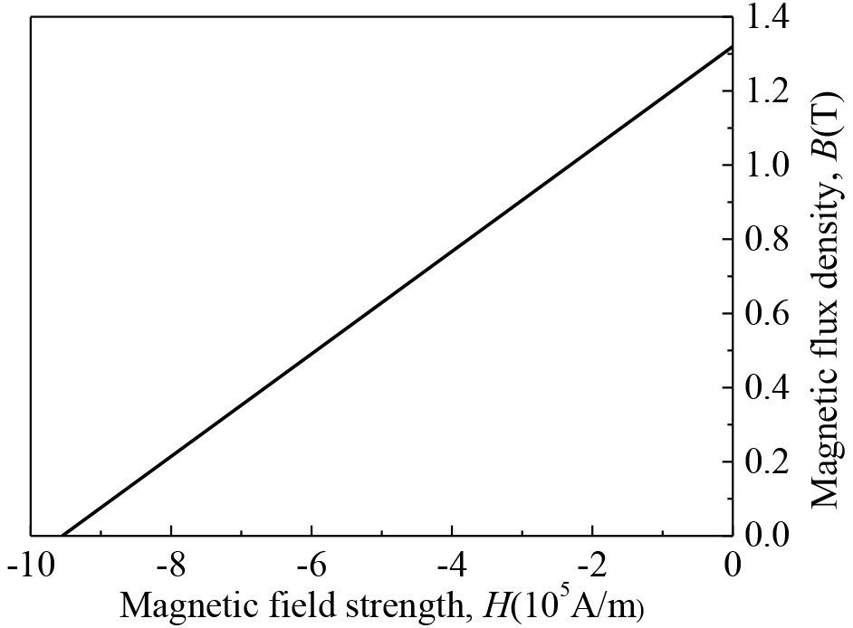

Considering that the magnetic circuit is symmetry, only one of these loop paths needs analyzing. In order to optimize the performance of the MFD, the influence factors of the MFD in the air-gap, such as the parameters of the permanent magnet and the thickness of the PS, are analyzed with the finite element method.
The geometric parameters of permanent magnet such as the height, the sector-angle, and the width in the radial direction will influence the performance of the MFD in the air-gap. However, the width of magnet has been determined by the effective length of force-generated part in the moving coil. Therefore, the sector-angle and the height of permanent magnet are analyzed.
In order to evaluate the magnetic field characteristic in the air-gap, the MFD along the curve line from point p
Distribution of the MFD for the different pole-arc coefficient. Distribution of the MFD for the different height ratio of permanent magnet to air-gap.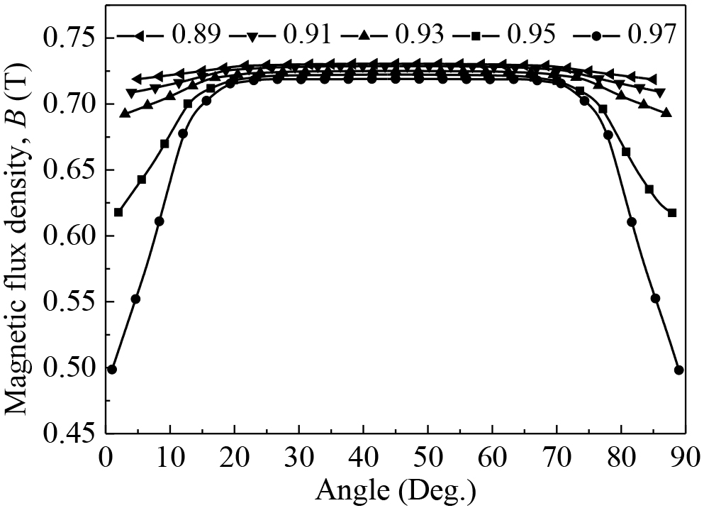
In Fig. 11, it can be observed that, with pole-arc coefficient increasing, the MFD distribution curve is gradually moving down. However, the difference of the value of MFD is very small in the middle range. In the meantime, the more the pole-arc coefficient, the smaller the effective straight section of the MFD, due to the interaction of the adjacent permanent magnets. So it is benefit to select the smaller pole-arc coefficient to decrease the effect of the adjacent permanent magnets under the condition of meeting the demand of the angular displacement and the install location of permanent magnets.
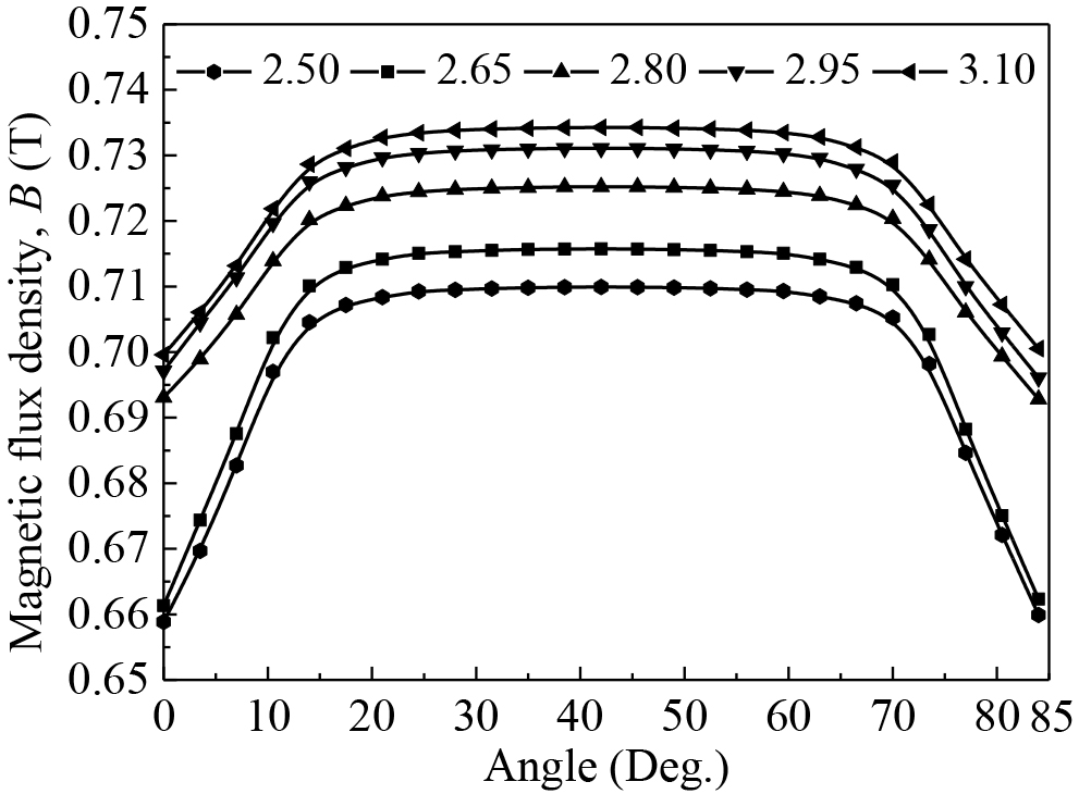
For the theoretical design index of the magnetic circuit in the air-gap, the average MFD is greater than 0.7 T, so the height ratio of permanent magnet to air-gap is at least 2.50 by preliminary analyzing and calculating [17]. Considering that the height of permanent magnet will be influence the magnetic field intensity in the air-gap, when the height of air-gap remains unchanged, the distributions of the MFD in the case of the different height ratio are calculated as shown in Fig. 11, in which the height of permanent magnet is changed from 15 mm to 19 mm at interval of 1 mm.
In Fig. 11, the MFD is increasing with the height ratio of permanent magnet to air-gap increasing. But, the relative increase of the MFD is sharp first and then becomes flat due to nonlinear increase of the magnetic reluctance of the magnetic circuit with the height of permanent magnet increasing [18].
Since the material of the PS is pure iron, whose magnetic permeability is far higher than the air, the magnetic flux through the interface between the PS and the air-gap will greatly be changed, which has been explained in Section 3.
In order to verify the feasibility of the DMSMC with PS to realize the high and uniform MFD in the air-gap, the MFDs of the DMSMC without and with PS are compared. The distribution of the MFD along the curve line
Distribution of the MFD of the DMSMC without and with PS. Distribution of the MFD for the different thickness ratio of the PS to permanent magnet.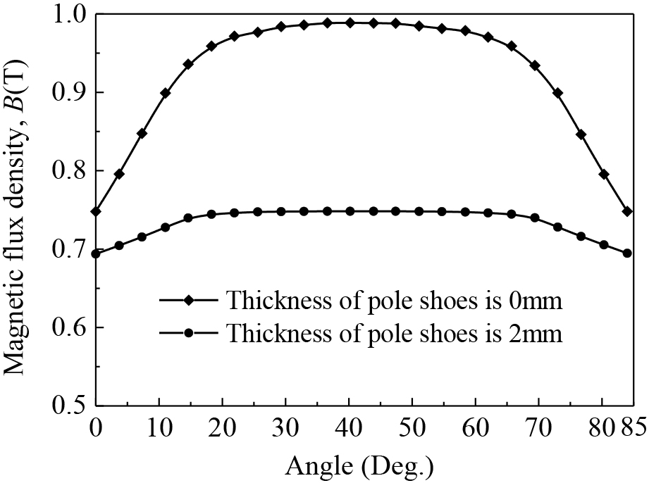
As shown in Fig. 13, for the DMSMC with PS, the distribution curve of the MFD is flat in the middle range, and the uniformity of the MFD is prominently improved although the maximum MFD goes down a little. In the meantime, the gradient of MFD is changed sharply at the both ends of the permanent magnets due to their fringe effect.
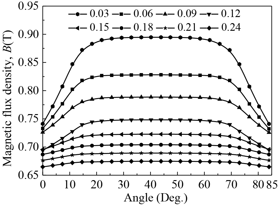
To obtain both high and uniform MFD in the air-gap, the thickness of PS is further analyzed. The distributions of the MFD under the condition of the different thickness ratio of the PS to permanent magnet are shown in Fig. 13, in which the height of permanent magnet is 17 mm, and the thickness of PS is changed from 0.5 mm to 4 mm at interval of 0.5 mm.
As shown in Fig. 13, the MFD distribution curve is decreasing gradually with the thickness ratio of the PS to permanent magnet increasing. But the larger the thickness ratio, the better the smoothness of the MFD curve. So the thickness ratio should be properly selected according to the intensity and uniformity in the air-gap magnetic field.
The optimized DMSMC with PS has already been applied to the electromagnetic angular vibration exciter prototype as shown in Fig. 15.
Prototype (a). Lower magnetic circuit. (b). Moving coil. (c). Angular vibration exciter. Distribution of the MFD in the prototype.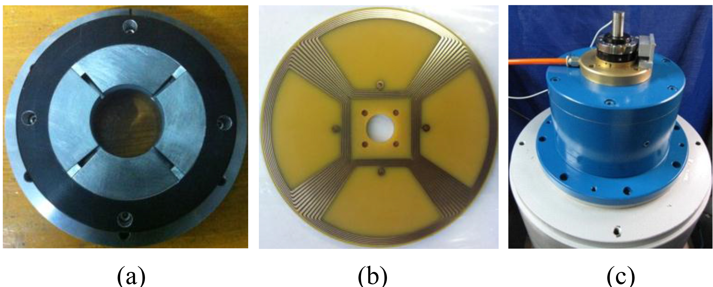
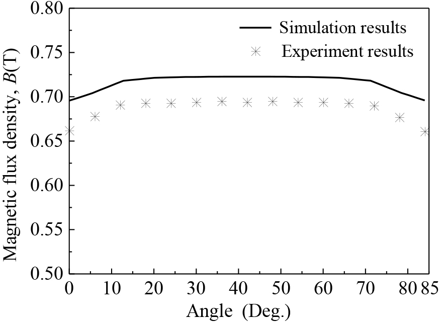
To validate the high and uniform MFD of the magnetic circuit in the air-gap, the MFD of the prototype is measured with a gaussmeter. The curve line
The experimental and simulation results of the MFD are compared in Fig. 15, which have the similar shape along the test points, and the measured MFD is a little smaller than the simulation results, and the relative error with two results is about 5% due to the influence of material parameters (geometric parameter, magnetic characteristic parameter, and so on) and installation gap between different materials. Anyway, it can be seen that the DMSMC with PS can meet the designed demand of the high and uniform MFD.
A double-magnetic-source magnetic circuit (DMSMC) with pole shoes (PS) for the electromagnetic angular vibration exciter is presented and analyzed. Based on the theory analysis and finite element simulation, it has been found that the DMSMC with PS can realize high and uniform MFD in the axial air-gap, while the double-magnetic-source can increase the MFD and the PS can improve the uniformity of the MFD. The optimized magnetic circuit has been applied to the angular vibration exciter prototype. The experimental results show that the MFD is high and uniform in the axial air-gap, which agrees basically with the simulation results, and will be satisfied the designed demand for the high quality of electromagnetic angular vibration exciters.
Footnotes
Acknowledgments
This research is sponsored by the National Key Scientific Instrument and Equipment Development Projects of China (2013YQ470765), the Science Fund for Creative Research Groups of Natural Science Foundation of China (51521064), the National Natural Science Foundation of China (51375443), the Zhejiang Provincial Science Fund for Distinguished Young Scholars (LR12E05001) in China, the Key Laboratory of Advanced Manufacturing Technology of Zhejiang Province (2016KF05), and the State Key Laboratory of Fluid Power and Mechatronic Systems.