
Abstract
This paper presents, first a d-q purely mixed model including the mutual leakage flux and a digital field oriented control of a double star induction motor using a two-level six-phase inverter; seconds a PI regulator to control the speed and the stator current of DSIM. To achieve a control of this machine two voltage source inverter of PWM techniques are introduced. A comparison with a traditionally (PI) controller is discussed. Extensive simulation is performed and it is shown that the reduction of the current harmonics is in essence almost the same as in another recently developed DFOC scheme. However, the achieved torque ripple reduction makes the scheme superior when compared to the existing approaches. At the same time, developed scheme retains qualities of conventional DFOC schemes, such as simple structure and fast response. Its additional beneficial feature is the easiness of implementation.
Keywords
Introduction
Nowadays, multi-phase drives are used in all applications requiring reliability, since a multi-phase drives can operate with an asymmetric winding structure in case of loss of one or more inverter legs/machine phases [1, 2]. The major application areas of multi-phase drives are a more electric aircraft, ship propulsion, electric and hybrid electric vehicles, locomotive traction, and general high-power industrial applications [3, 4]. Among the variety of multiphase machine options, an asymmetrical six-phase machine is preferred since it can be easily obtained by rewinding the stator of a three-phase machine as long as the number of slots per pole per phase is an even number [5, 6]. Use of the double star induction motor (DSIM) drives, especially for high-power applications, has considerably increased over the past 40 years [7, 8, 9, 10].
Double star induction motor possess inherent advantages over the three-phase counterparts, such as better fault-tolerant characteristics, power/current splitting into a higher number of converter legs enabling reduction of the required semiconductor rating, possibility of independent control of multiple motor drives using a single inverter, and suitability for designing fully-integrated on-board battery chargers for electric vehicles, as discussed in recent surveys [11, 12, 13]. With these advantages, the DSIMs are used in several applications, especially those requiring high power such as electric/hybrid vehicles, locomotive traction and electric ship propulsion [14, 15].
The double star induction machine has two sets of three-phases windings spatially phase shifted by 30 electrical degrees with isolated neutral points and each star winding is fed by a three-phase voltage source inverter (VSI). However, a disadvantage of multi-phase machine is the complexity of the control algorithm. The direct field-oriented control (FOC) method is today widely used in various AC drives applications to achieve high performance control of three phase machines, can be extended to multiphase machines [16, 17]. The controller design of a DFOC AC machine drives plays a crucial role in control performance, the conventional PI controllers is employed in speed and current controller. These controllers are very sensitive to machine parameter variations, load disturbances and along with step changes of command speed [18, 19].
A FOC scheme is developed, which incorporates the best performing decoupled modulation method. Dynamic performance of the DSIM is then examined. The results show that the developed modulation technique, in addition to avoidance of the capacitor overcharging problem, ensures high dynamic performance expected from a FOC drive.
In this paper, two control strategies, PI and DFOC, are considered to adjust the speed of the drive system. The schematic diagram of a direct field-oriented control (DFOC) drive for DSIM using conventional PI controllers is shown in Fig. 4. This paper is organized as follows: The DSIM d-q mixed model is provided in Section 2, and the DSIM control strategy is presented in Section 3. Next, the proposed DFOC structure is given in Section 4, and the results are presented and discussed in Section 5. Finally, conclusions are presented in Section 6.
Modeling of the DSIM
The motor is modelled in the stationary reference frame. The modeling and control of DSIM in the original reference frame would be very difficult. For this reason, it is necessary to obtain a simplified model to control this machine. As consequence, also the mathematical modeling approach of DSIM is similar to the standard induction machine ones and usually it is obtained under the same simplifying assumptions: the windings are sinusoidally distributed and the rotor cage is equivalent to a three-phase wound rotor. The stator and rotor voltage/flux equations of the phase-variable motor model and subsequent application of the rotational transformation in conjunction with the rotor winding lead to the motor model are given with:
and for the rotor circuit we have:
where
where
The electromagnetic torque and dynamic equations can be expressed as:
Where
Reference frame
The direct vector controller is derived from the dynamic equation of the machine in the synchronously rotating reference frame
The resultant rotor flux
The DSIM control principle is similar to the well-known rotor FOC used for the classical asynchronous motor.
The rotor currents in terms of the stator currents are derived from Eqs (11) and (12) as:
Substituting for d-q rotor currents from Eqs (18) and (19) into Eqs (5) and (6), the following are obtained:
where
where
The DFOC seems to be an interesting alternative to the PI controller, which cannot yield good control performances if the controlled system is highly nonlinear and uncertain. Block diagram of the DFOC is shown in Fig. 1.
Bloc of direct rotor field-oriented.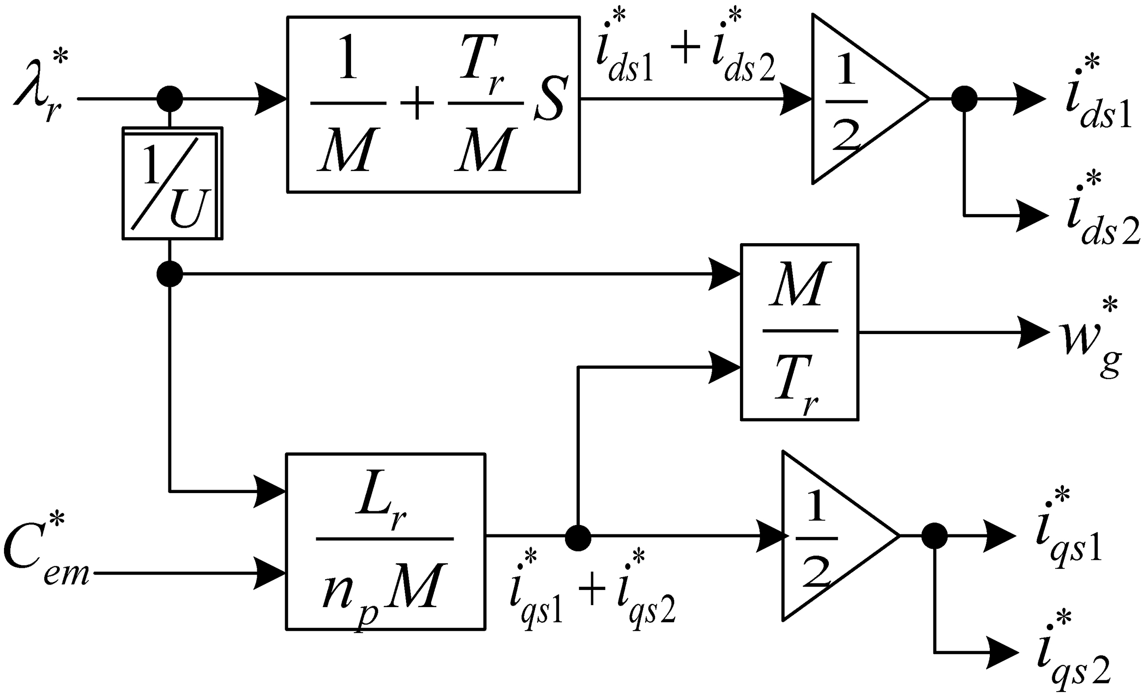
Bloc of decoupling voltage.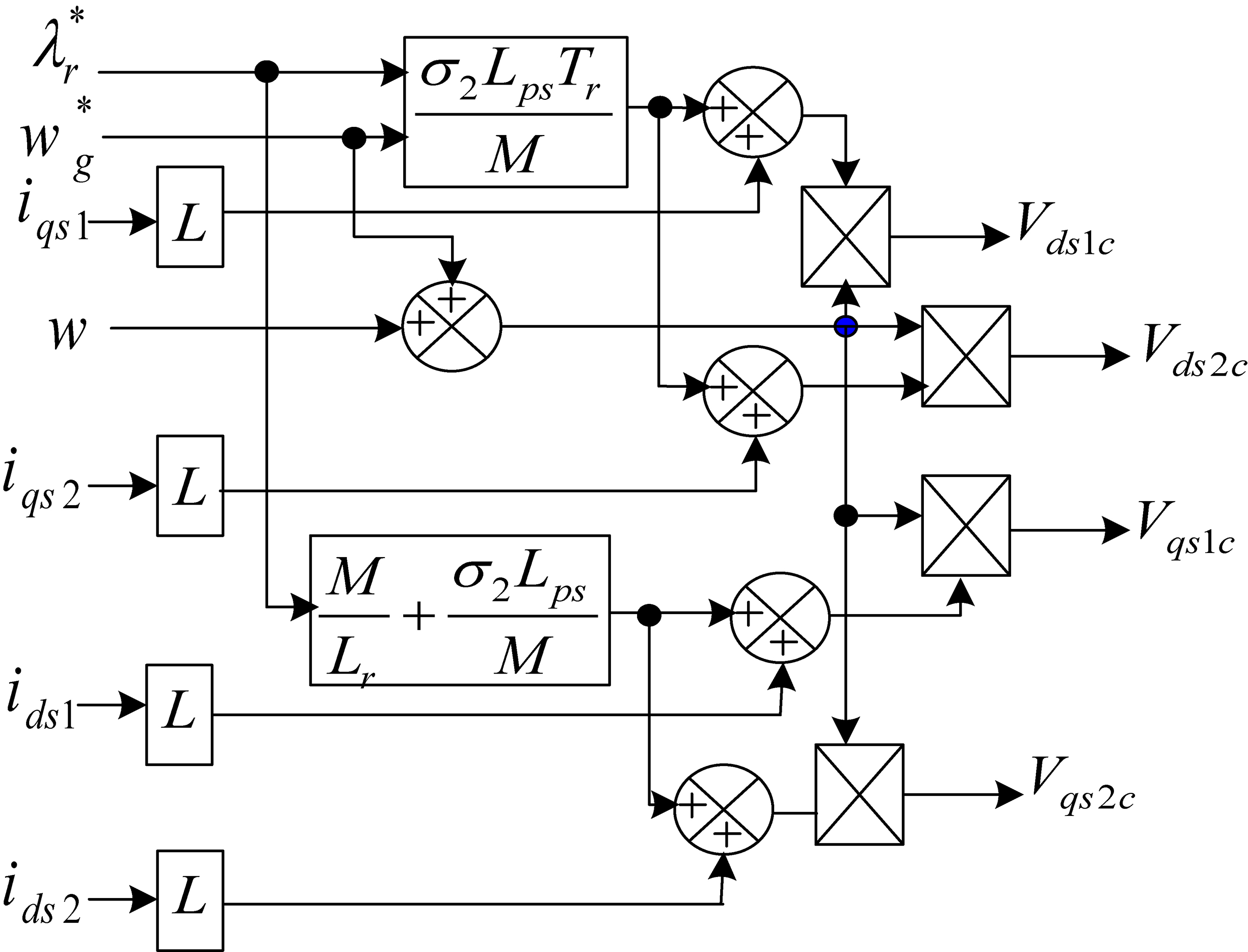
By introducing stator flux expressions Eqs (25)–(28) into voltage expressions of the DSIM Eqs (1)–(4), the following are obtained:
Considering that the first parts of voltages expressions are the linear parts and adding PI currents regulations to achieve perfect decoupling.
where
The first reason for introducing the current control is the elimination of stator dynamics. Adding compensation terms to make d-q axes completely independent. So we pose the following system which compensates the errors producing during the operations of decoupling, as shown in Fig. 2.
The rotor flux was estimated by the following expression:
module of rotor flux is calculated by:
The PI controller parameters
To get a well damped behaviour, we use the poles placement approach proposed by [13] as shown in Fig. 3.
Closed loop stator current.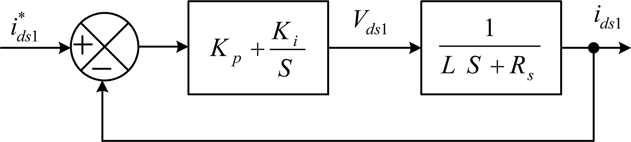
Let
The architecture of the proposed DFOC of a double star induction motor drive supplied by two CRPWM is reported in Fig. 4. The DSIM is driven by two inverters, controlled with a conventional Field Oriented Control (FOC) scheme. Using the proposed control strategy, the DFOC of a double star induction motor drive supplied by two CRPWM is shown in Fig. 4. This allows a simple extension of the RFOC principle in that the rotor flux linkage is maintained entirely in the d-axis, resulting in the q-axis component of rotor flux being maintained at zero. This reduces the electromagnetic torque equation to the same configuration as that of a dc machine or a rotor flux oriented three-phase machine. Thus, the electromagnetic torque and the rotor flux can be controlled independently, by controlling the d and q components of stator current. For this purpose, a vector control receives the speed and rotor flux requests and generates the commanded values of torque and flux producing components of stator current
Direct rotor field-oriented control scheme for DSIM drive.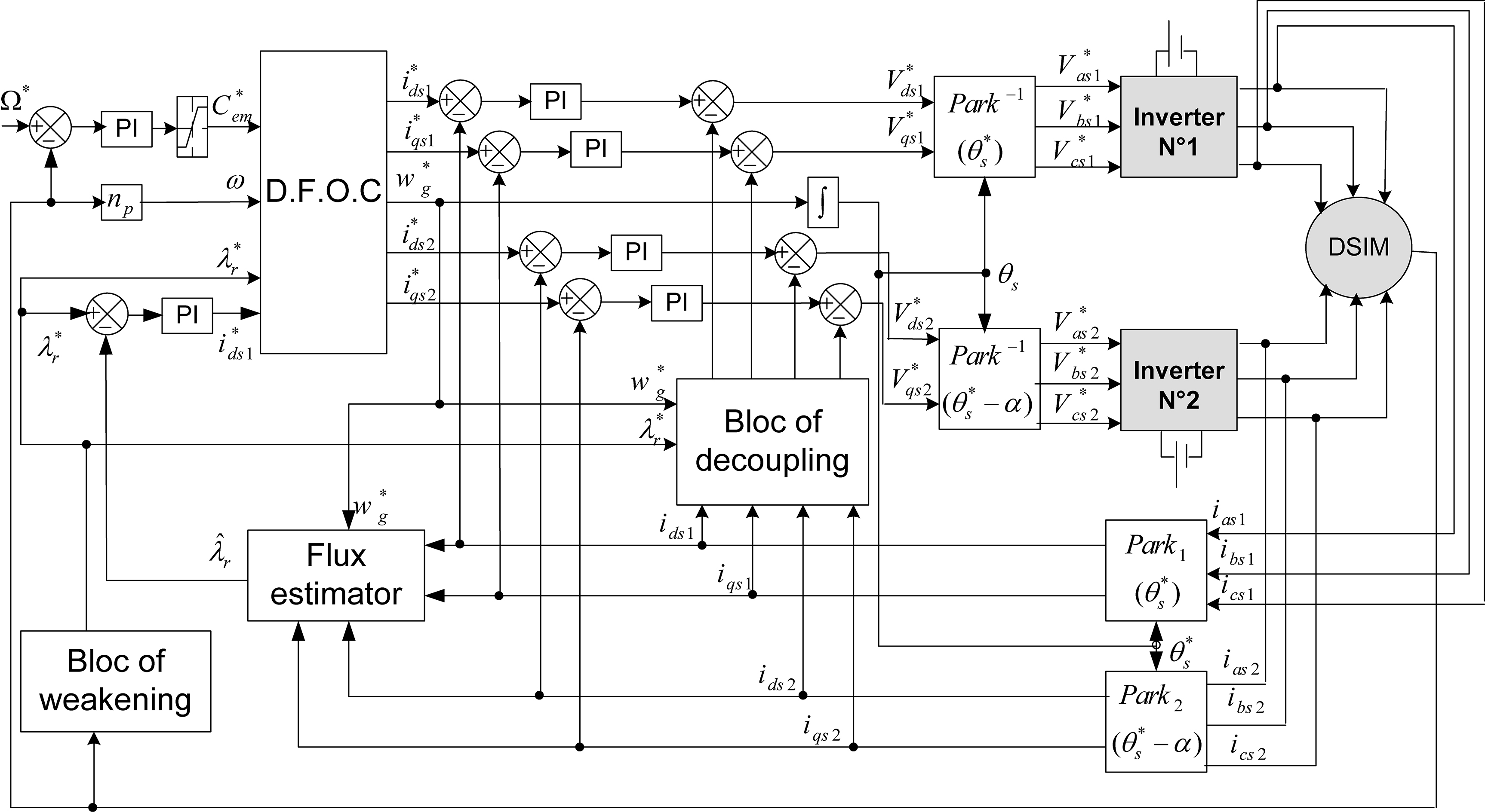
Many tests were performed to evaluate the performance of the DFOC-DSIM, In order to compare the performances of the speed-control DFOC-DSIM; the same tests are made with the PI controller. The speed responses are observed under different operating conditions such as a sudden change in command speed, step change in load, etc. Some sample results are presented in the following section.
The Figs 5 and 6 present the transient responses for DFOC of DSIM drive using the proposed PI with applying a step increase in load (from zero to rated torque) then removing the load after 2 seconds, the reference speed is 300 rpm. At both speeds, the PI offers a faster response time with no overshoot, and rejects the load disturbance very quickly with smaller overshoot/undershoot.
Electromagnetic torque (N.m).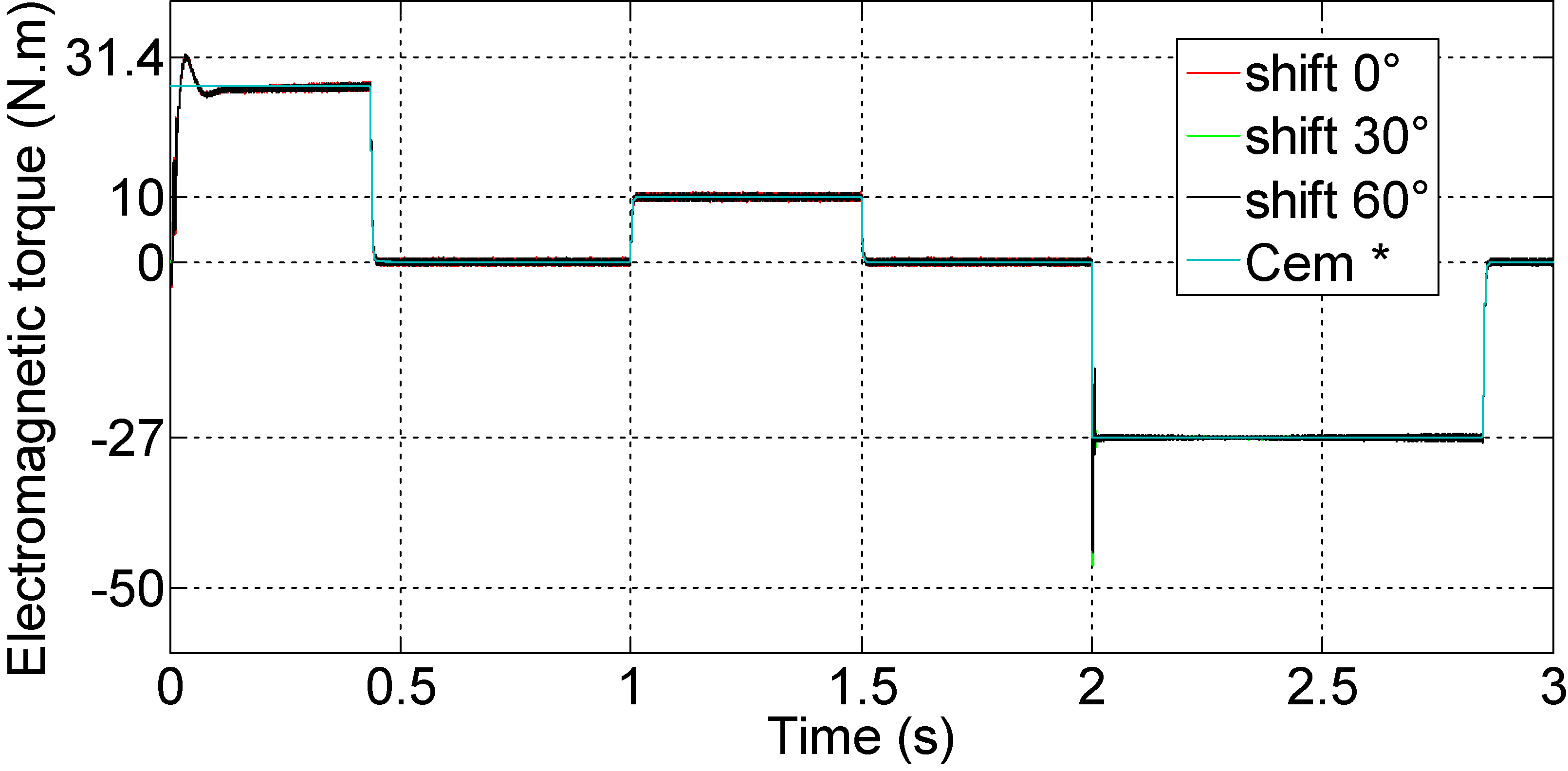
Zoom of electromagnetic torque in steady state with load.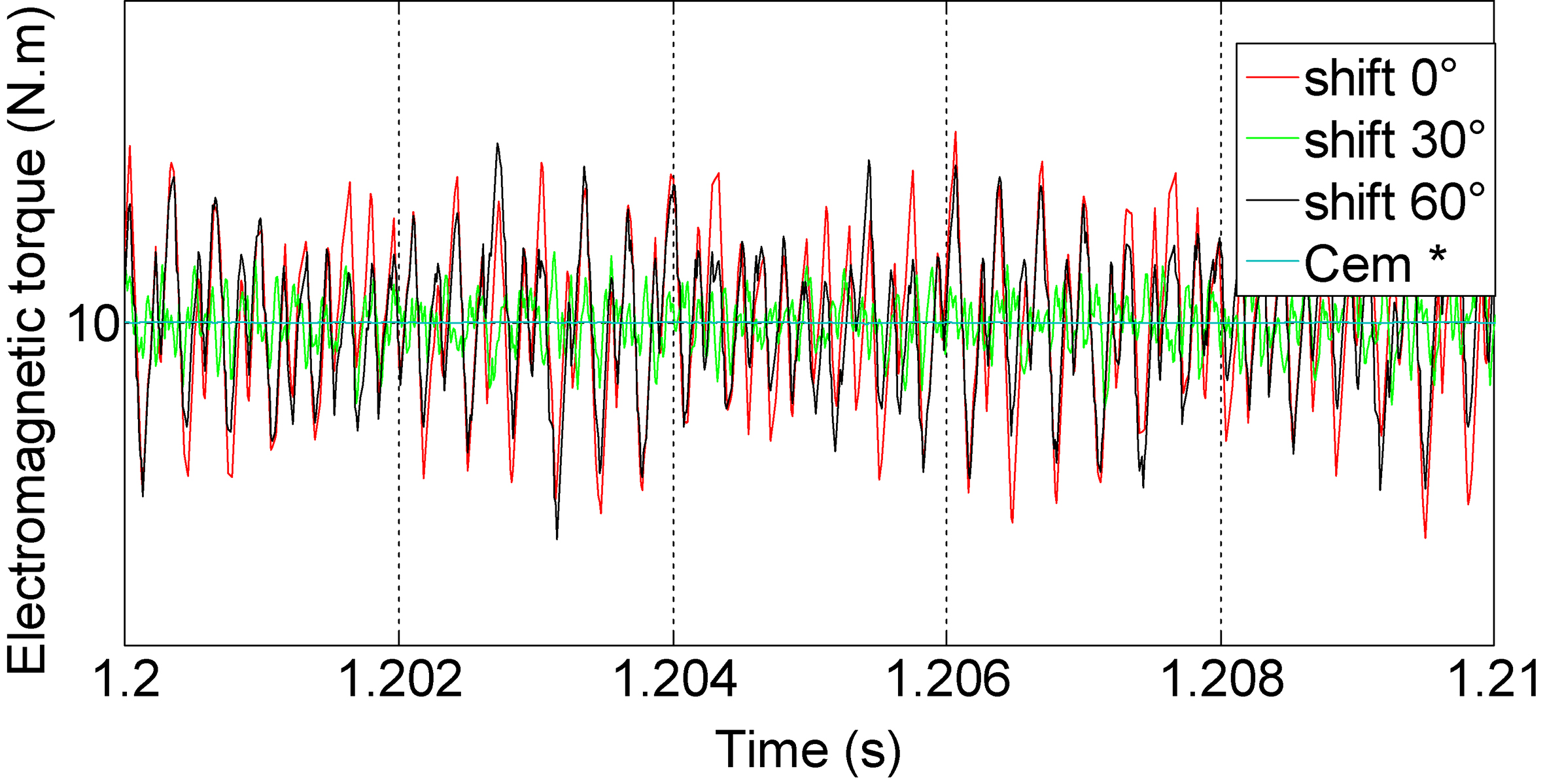
Rotor speed.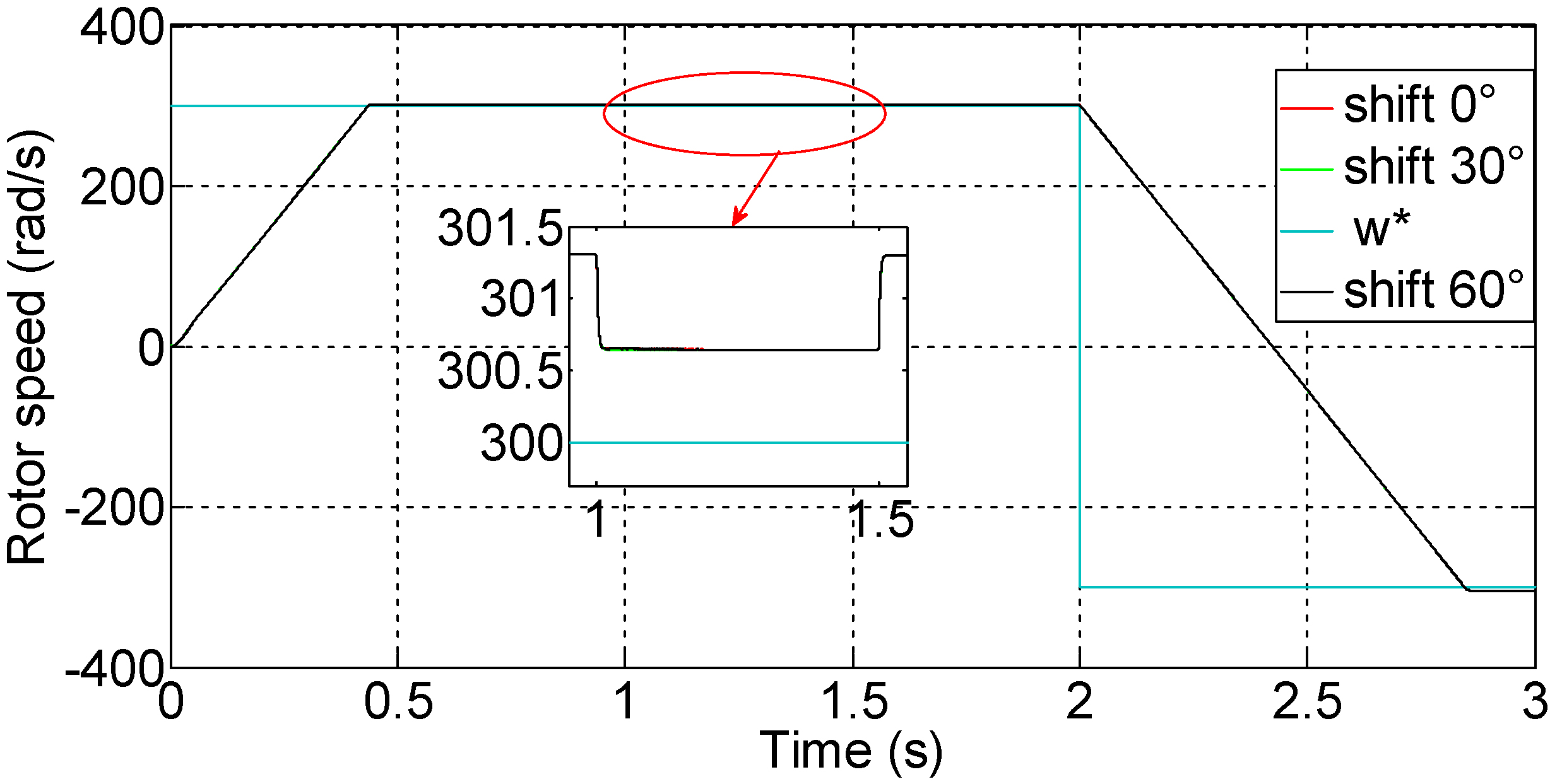
The influence of the speed variation on the electromagnetic torque response is shown in Fig. 5. It is seen that transient oscillations occur due to the coupling terms between the d-q axes. It can be seen that the amplitude of transient oscillations is minimized with PI due to its better rejection of perturbations. Also, this result shows that the DSIM drive using PI has good quality and guarantees stability under variable load and speed.
Waveform of stator current per phase ‘a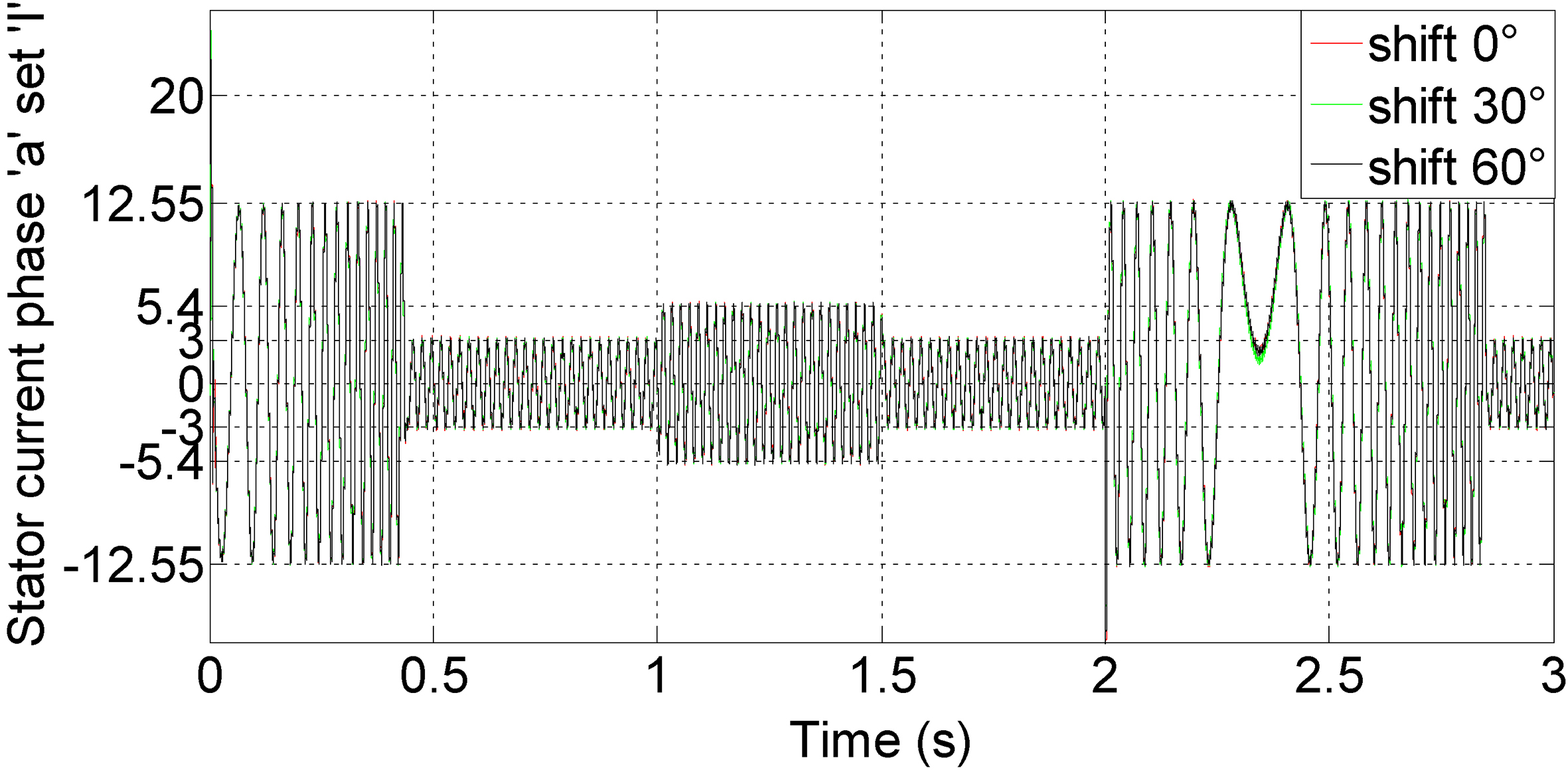
d-q axis stator current of first set for 0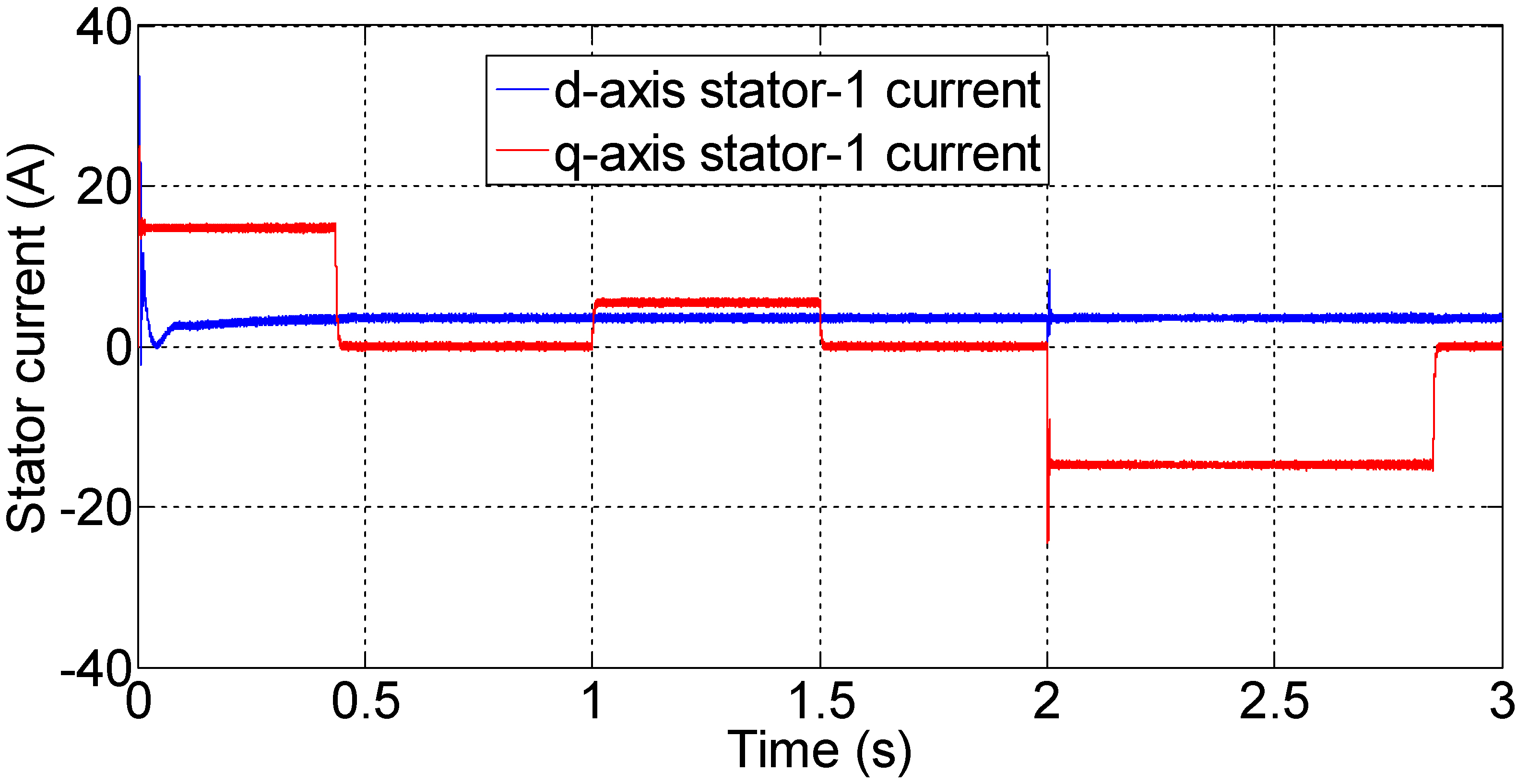
d-q axis stator current of second set for 0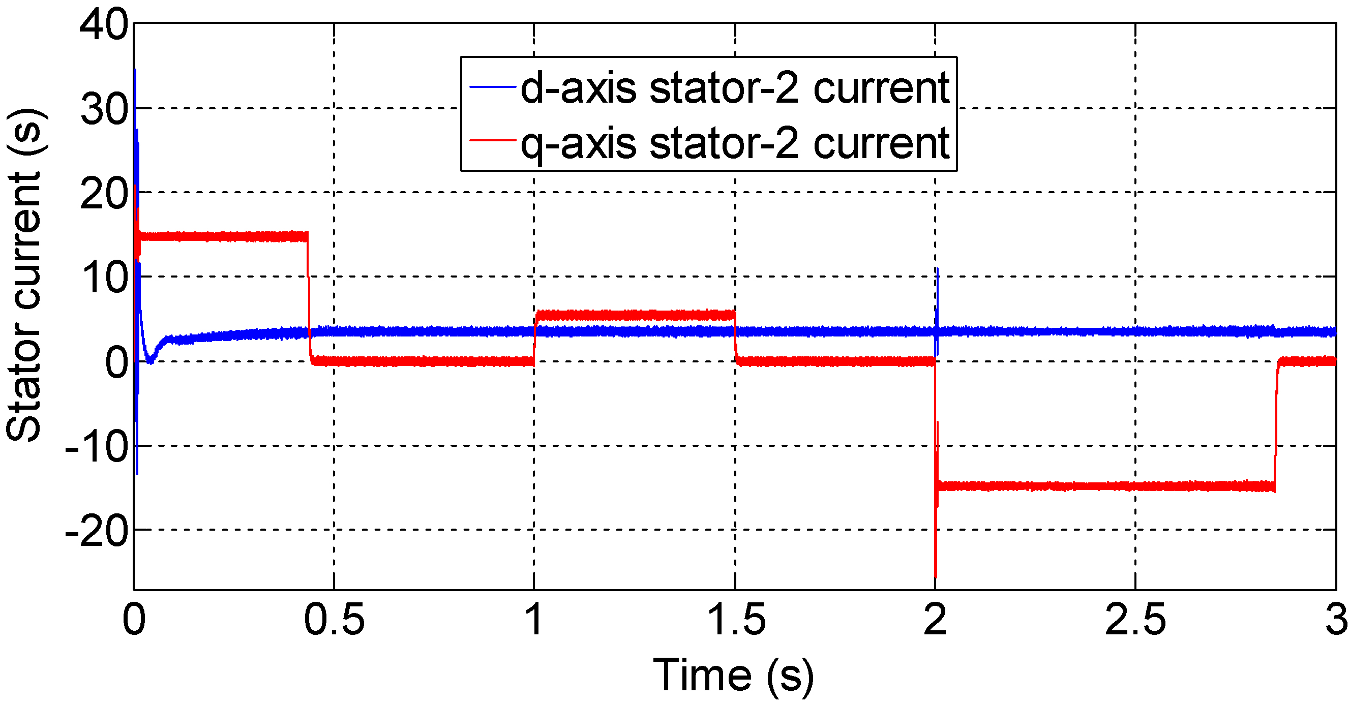
The Figs 7 and 8 present the rotor speed and stator current response of the DSIM to a step change in command speed at no load. The change in command speed is realized after 2 seconds. The rotor speed obtained by the PI track very quickly the desired reference speed. The Figs 9 and 10 show that the DSIM developed a stator current in any change of speed reference for forcing the actual rotor speed to follow the desired reference.
As shown in the previous figures, there seems to be no speed change when a step load change is effected as the large speed range selected for y-axes speed. When y-axis is zoomed, there is a speed variation of 0.7 rad/s, as observed in the extended view of speed. Figures 9 and 10 show the reference and simulated value of d- and q-axes stator current-1 and 2 current, respectively, when a step load change of 10 N.m at 1.0 s is affected.
Results of a set of tests showing the impact of DSIM’s parameters variations on dynamic/steady-state performances with the two controllers is presented in Fig. 10.
Finally, the simulation results of the DFOC DSIM using PI controller is analyzed regarding load torque, speed and inertia moment variations. These results confirm that the PI controller demonstrates robustness under various operating conditions and shows a very satisfactory performance.
In this paper, the performances of speed control with PI controllers for direct field-oriented DSIM drive are presented, the simulation results show that the PI controller give a good performances with taking account the effect of mutual leakage inductance between the two stator winding. The presented results show that a PI control method can be a very attractive solution for devices using DSIM such as electric/hybrid vehicles, traction locomotives and electric propulsion ships. The control methodology proposed here can be simply extended to other electric motors. Future work will address the experimental implementation of this proposed control scheme and the design of a speed sensorless controller.