



Abstract
Due to their advantages of high efficiency, high power density, and strong fault-tolerance ability, fractional-slot concentrated-winding permanent-magnet (FSCW-PM) machines are of particular interest in the applications such as wind power generation and electric vehicles. However, FSCW-PM machines suffer from rich winding magnetomotive force (MMF) space harmonics by the armature reaction field, which may increase eddy current loss. In this paper, a new low harmonic FSCW-PM machine is designed, which can reduce some space harmonics of low order in the air-gap flux density. A new magnetic equivalent circuit (MEC) model is developed to analyze the designed PM machine, which offers less computation time and more calculation accuracy. Finally, a prototype machine is built and the measured results verify the theoretical analysis and the developed MEC model.
Keywords
Introduction
Fractional-slots concentrated-windings (FSCWs) has been adopted in permanent-magnet (PM) machines more widely as an alternative of integer-slots windings for applications which require high efficiency, high filling factor, low cogging torque, fault tolerance, cost-effectiveness and good field-weakening capability [1, 2, 3]. However, the existence of rich space harmonics in the stator magnetomotive force (MMF) distributions of the armature reaction field is undesirable, such as localized core saturation, eddy current loss in PMs, additional core losses in rotor and stator, and noise and vibration, which have been the main disadvantages of FSCW-PM machines [4, 5, 6]. Also, thermal demagnetization of the PMs may take place owing to this overheating and the corresponding excessive temperature.
Ref. [7] improved the reluctance torque of FSCW-PM machines with different slot-pole configurations, but still suffering from harmonics. Considerable approaches have been proposed to analyze harmonics in order to reduce the losses, including using nonuniform tooth width, having asymmetric number of turns, doubling slot numbers to apply phase shift and applying delta-star winding with different numbers of turns [8, 9]. As a result, the machine performances are improved, such as torque density and winding factor. Meanwhile, multiphase delta-star winding type has exhibited great promise in improving the MMF distribution together with enhancing fault-tolerant capability [10]. However, it should be noted that the complex winding distribution and flux paths of the delta-star windings design will increase the analysis difficulty of the magnetic field. The 2-D finite-element analysis (FEA) method is time-intensive, so it is inappropriate for optimization of this delta-star machine. Hence, it is important to develop a less time consuming model for the delta-star windings machine while maintaining the high accuracy of FEA. However, the existing modeling techniques, such as magnetic equivalent circuits (MECs) [11, 12], analytic modeling and 2-D equivalent FEA model either, fail to achieve results accurately, exhibit poor agreement with FEA results, or take too much computation time. To the author’s knowledge, up to now, no accurate model are reported for low harmonic FSCW PM machines with delta-star winding, which has both efficient computing time and reliable computing accuracy. Hence, an efficient model can help to reduce the optimization time based on winding topology when designing a low harmonic machine.
This paper will design a new delta-star windings FSCW-PM machine and develop its MEC model, which possesses high analytical accuracy and short computation time. This model is based on MEC theory and adequately utilizes the method of equivalent replacement, but a unique delta-star winding is applied in the model instead of the traditional winding type. It should be noted that the delta-star winding topology has a great effect in reducing harmonics, while this topology has never been optimized by using MEC model. Moreover, different numbers of turns result in the varieties of the dual three-phase winding formation and the MMF space amplitudes and phases based on theoretical design and analysis, which requires the optimal MEC model to change the winding distribution topology as the delta-star theory. Last but not the least, the improved MEC model for low harmonic design can retain the advantages of FEA, and indicate the low harmonic design advantages without much computational expense. The main goal of this paper is to calculate the key electromagnetic performance for a newly designed low harmonic FSCW-PM machine by a practical MEC approach. In Section 2, a new winding connection is designed and applied in a delta-star windings FSCW-PM machine in order to reduce the undesired harmonics. In Section 3, based on the theoretical analysis, a dynamical MEC network will be developed to predict the electromagnetic performances of the designed machine, e.g., flux linage, electromotive force (EMF). In Section 4, a 12/10 delta-star windings FSCW-PM prototype will be built and its MMF harmonic content will be calculated both in MEC and FEM. At last, the conclusions will be drawn in Section 5.
Low harmonic design of FSCW-PM machine
Figure 1 shows the cross-section of a 12/10 FSCW-PM machine, which is composed of shaft, PMs, armature teeth and windings, and yoke from inside to outside. Halbach PM array is adopted in this machine. In conventional design features, skewing of the stator/rotor, optimization of the magnet pole-arc, distributed stator windings were applied to reduce cogging torque and improve EMF essentially, while this halbach design could provide an inherent sinusoidal air-gap field distribution, and strengthen the air-gap magnetic field while weaken the rotor magnetic field. The detailed parameter of this FSCW-PM machine is shown in Fig. 2, and listed in Table 1.
Key design parameters
Key design parameters
FSCW-PM machine.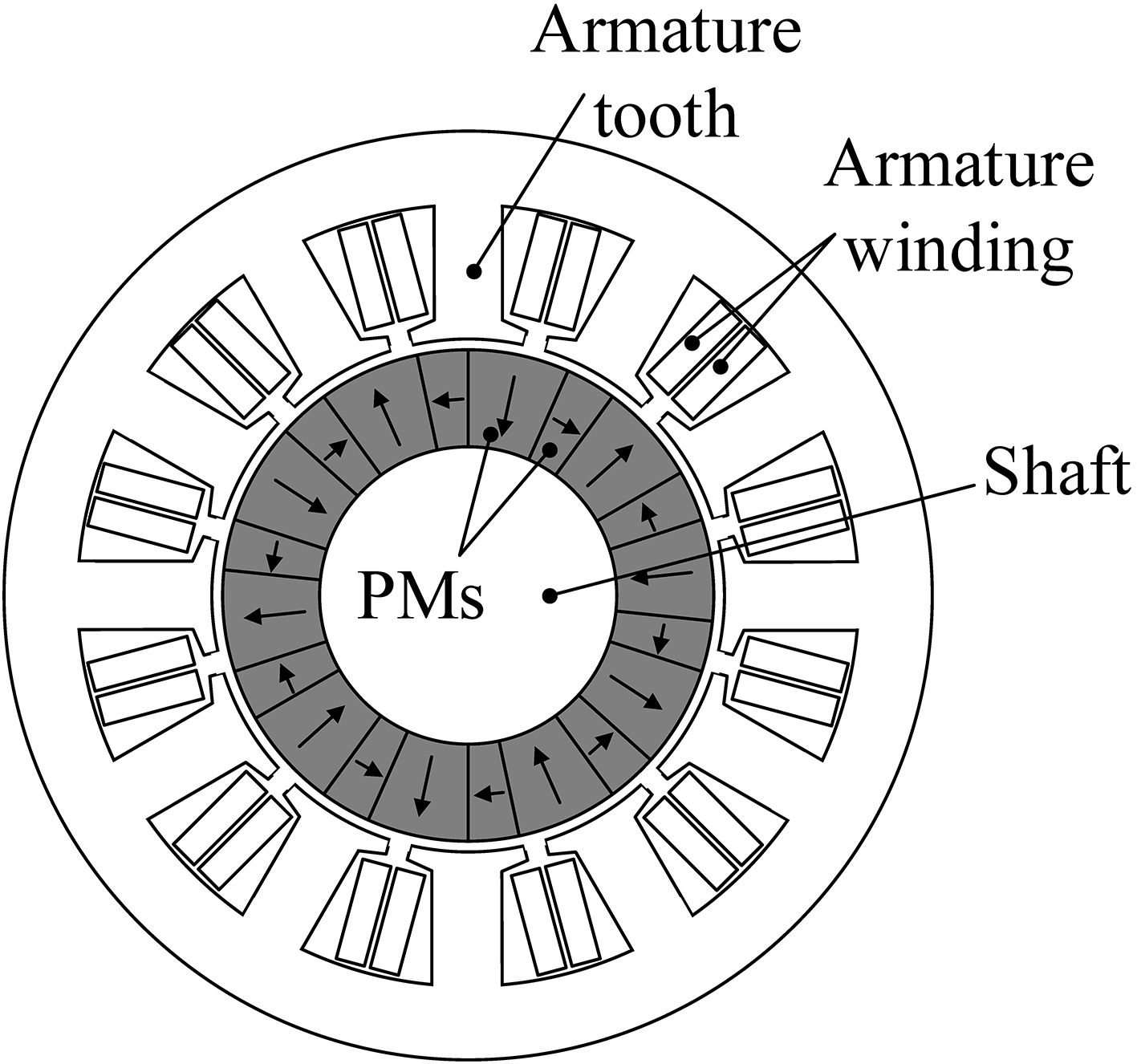
Detail parameters.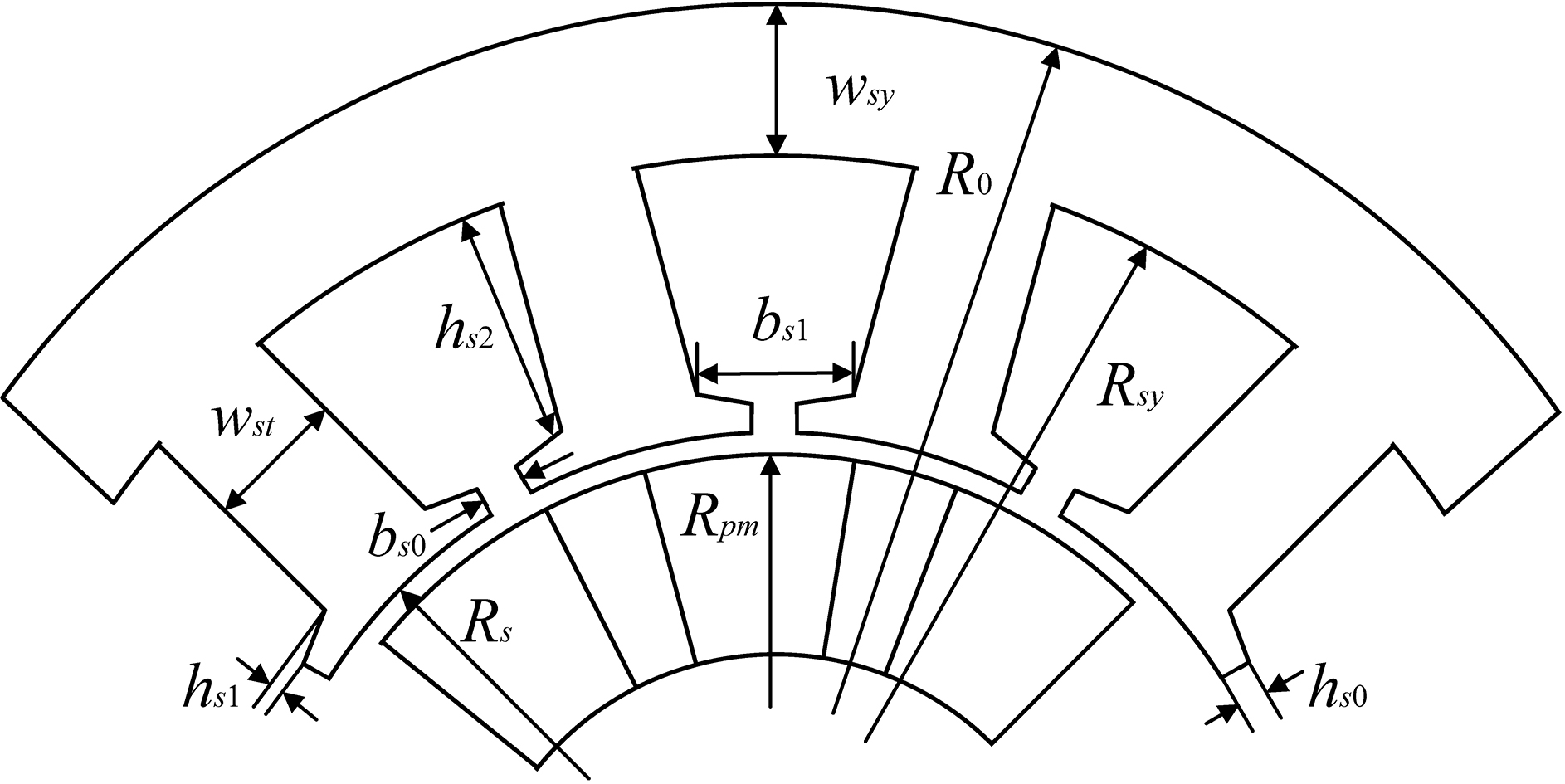
Star-delta connection of winding type.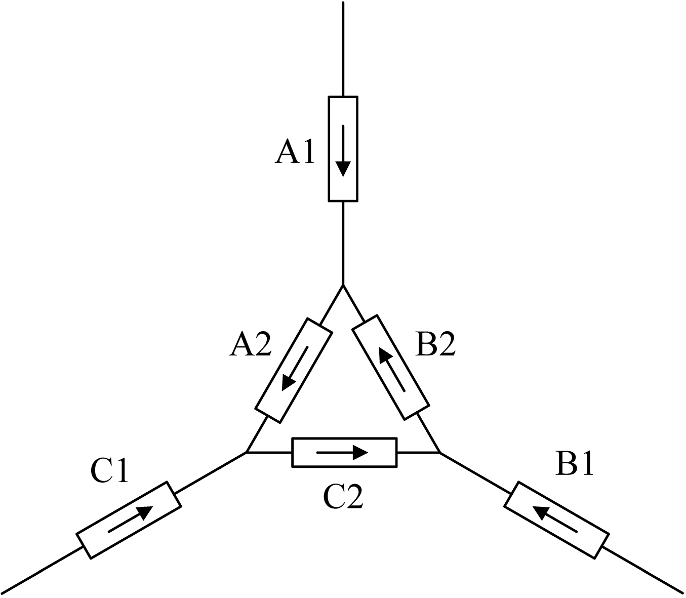
MMF harmonic distribution in phase A.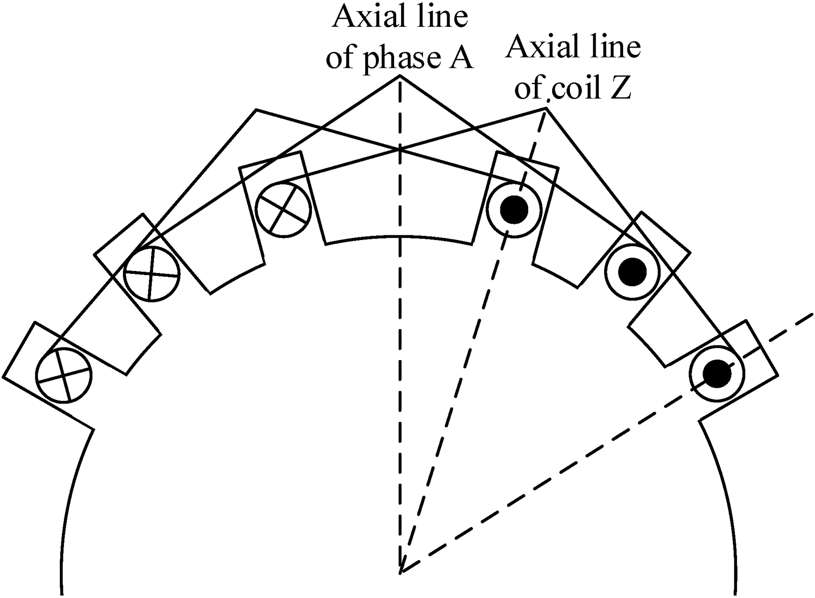
In general, it is an ordinary way that either star-connection or delta-connection winding types can be applied in FSCW-PM machine. However, as shown in Fig. 3, a low harmonic design adopts the combined winding type of star-delta connection, in which the input current amplitude and phase are altered by the transition of star-delta connection. The differences of amplitude and phase can be utilized to make the MMF space phase aligned or opposite, and some specific orders of winding harmonics content can be eliminated under an appropriate turn ratio.
Figure 4 shows the MMF in single-phase winding of a conventional three-phase FSCW-PM machine. For this machine, one side of phase A is chosen as the coordinate origin, which is supposed to set coil Z has a positive current flow. The radians of the coordinate origin lagging behind the axial line of one certain coil Z in phase A is
where
Since the space phases of odd harmonics are identical and the space phases of even harmonics are opposite in each two coils, the distribution factor of odd frequencies is equal to the distribution factor of phases in each phase. The distribution factor of even frequencies is zero because the composit MMFs cancel each other. Based on Eq. (1) and Fig. 3, the MMF harmonics of odd order corresponding to the 12/10 dual-winding FSCW-PM machine can be expressed as:
Moreover, for the composit MMF in three-phase winding, winding MMF of each phase can be decomposited into three parts, namely positive-sequence, negative-sequence and zero-sequence. The three-phase positive-sequence and negative-sequence components are three-phase symmetric, while the three-phase zero-sequence components are same in phase and magnitude. Hence the MMF of three-phase can be given as:
At the same time, the amplitude of MMF positive-sequence (pulsating MMF) of each phase can be given as:
where
Also, the amplitude of the composit MMF positive-sequence of three-phase is:
The amplitude of composit MMF negative-sequence of three-phase is:
In a conventional three-phase machine, the windings are three-phase symmetric in general, so one of
Distribution of windings.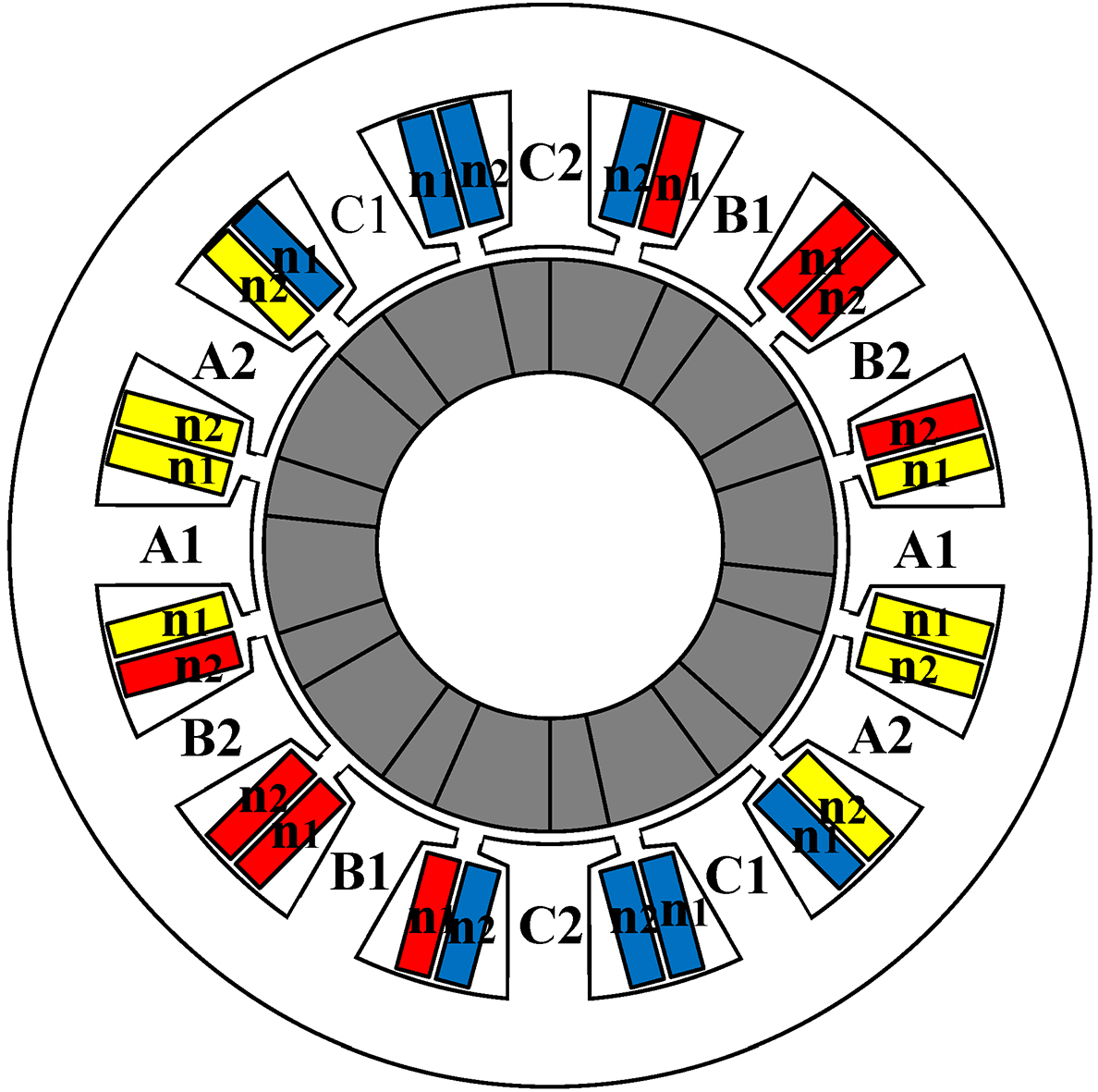
Phase vector of winding arrangements. (a) In phase. (b) Out of phase.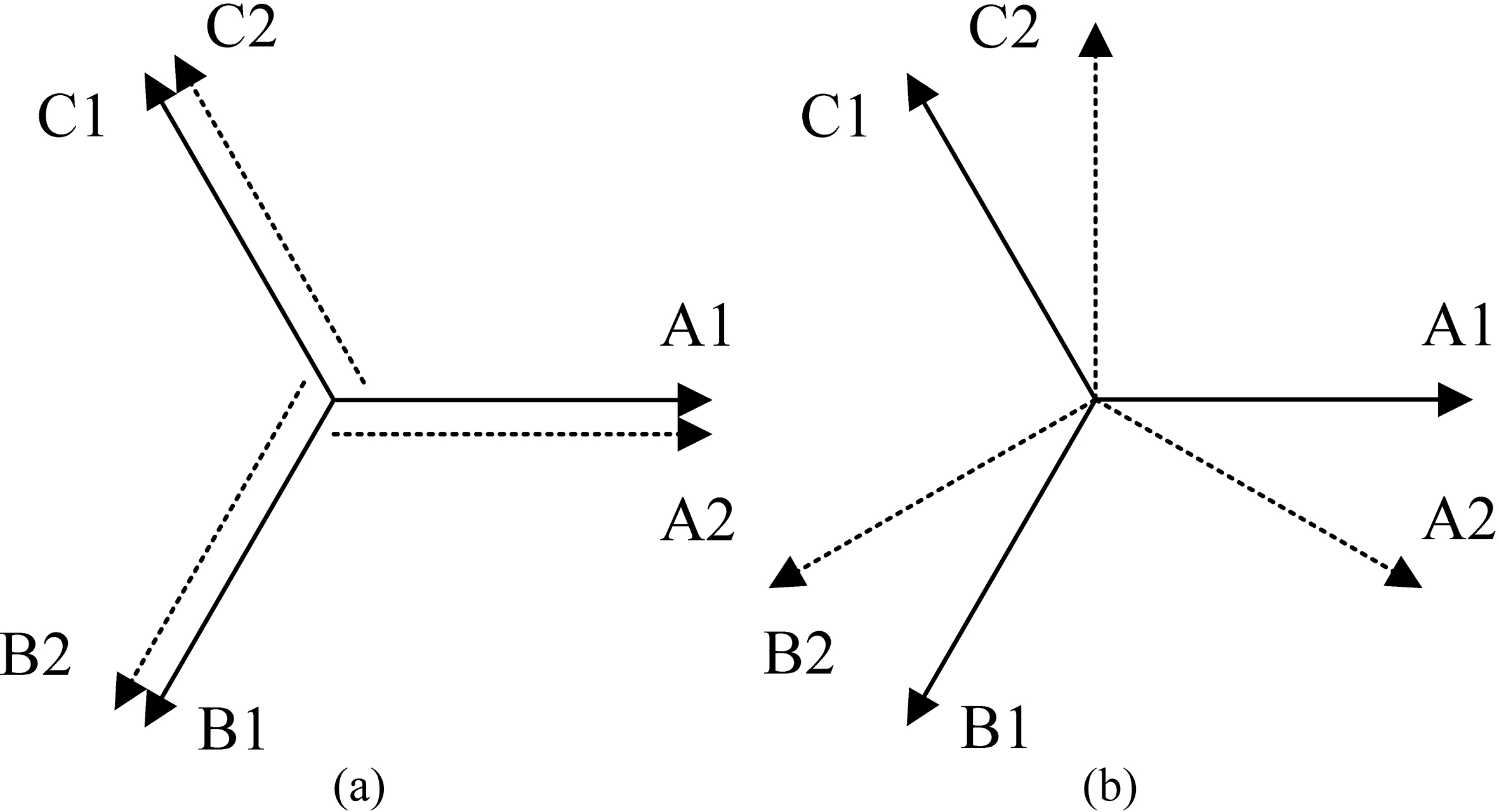
In this work, the new low harmonic type of winding connection is carried out, namely the two sets of three-phase windings. By way of example, the 12-solt 10-pole windings are configured into two three-phase system, as shown in Fig. 5. The type of winding connection has been shown in Fig. 3. According to the theoretical analysis, when the input currents through phase A1, B1 and C1 are positive-sequence, the composit three-phase MMF is round rotating MMF in positive direction. Also, the two windings are supplied with currents “in phase”, as shown in Fig. 6a. This means that the same current feeds phases A1 and A2 and similarly for phases B1 and B2 and phases C1 and C2. Alternatively, they can be supplied with currents out of phase of 30 electrical degrees, as shown in Fig. 6b. Based on the mathematical expression of winding composit MMF, the space phase of harmonics in single-phase winding MMF can be calculated as 0
Comparison in winding MMF harmonics.
Based on the foregoing design, only odd harmonics will exist in the single-phase winding MMF. Also, when they are not the fundamental order or slot harmonic, assuming that the turns of winding A1, B1, C1 are
where the plus-sign and minus-sign are determined by the type of harmonic. It is plus-sign if the harmonic is the fundamental order and slot harmonic, otherwise it is minus-sign.
Figure 5 also shows the turn ratio of each phase. It can be calculated that the first-, fifth-, 7
Since the new star-delta winding connection approach is proposed in FSCW-PM machine, analytical complicacy has increased significantly in magnetic field. When 2-D FEA is used to analyze the complex winding distribution and flux path, the complex star-delta connection transition is required, which is time-intensive and inappropriate for optimization. In this section, a new MEC model developed from magnetic circuit method will be built to analyze the designed PM machine, which offers less computation time with the high calculation accuracy of FEA. Besides, since the new MEC model applies the unique star-delta connection type, an optimal distribution topology is developed as the form of dual three-phase winding.
Principle of MEC model
In a static magnetic field, the Ampere Circuital Theorem and Law of magnetic circuit node can be given as:
where
Based on Eq. (8), the summary of magnetic flux which flows into one node is zero, known as Kirchhoff Current Laws (KCL). After discretization, a discrete form of Eq. (8) can be obtained as:
where
The magnetic flux through the cross-sectional area
Equations (8) and (11) are the basic principle of MEC model, and provide theoretical basis for the analysis of magnetic circuit. Then, the structure of machine can be finite-elementary divided and equivalent processed. By using the inherent similarity between the electronic circuit and magnetic circuit, the matrix of all nodes in magnetic network model is certain to be obtained with the KVL in electronic circuit theory.
Main structures in PM machine consist of air-gap, stator, rotor and windings. Since the variation of magnetic circuit, different equivalent models of elements are created separately. Based on actual magnetic field of machine, magnetic materials are equivalent as permeance and PMs are equivalent as magnetic source. The whole machine is simplified as a magnetic circuit. The permeance can be calculated via the magnetic material characteristics, geometry, or via the MMF across and flux through the tube.
In general, the permeance of a rectangular element can be given as:
where
Figure 8 shows the equivalent model of air-gap. A rectangular air-gap is created from the actual ring-shape based on the equivalent theory. Hence, the solution of air-gap permeance can be obtained as:
where
Effective area of air-gap under different 
Structure of stator branch and equivalent model.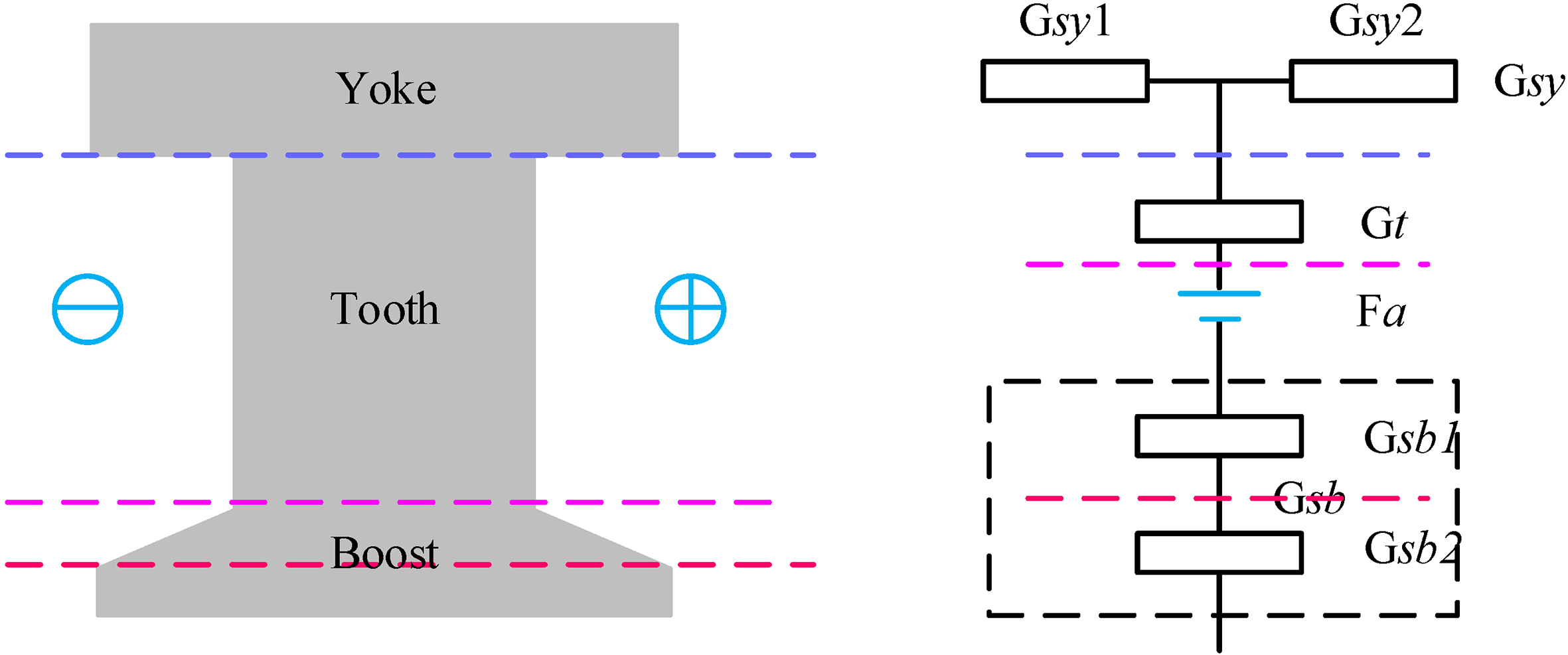
Figure 9 shows the structure of one stator branch and the equivalent models of the elements in accordance to the geometries. It can be observed that the stator branch is divided into three elements which are the yoke, the stator teeth and the teeth-boot. To improve the accuracy, the teeth-boot is divided into two parts, namely a rectangle and a trapezium. Four layers of permeances are established by three dotted lines which are yoke permeance layer
where
Vector decomposition of PMs. (a) Parallel magnetizing. (b) Tangential magnetizing.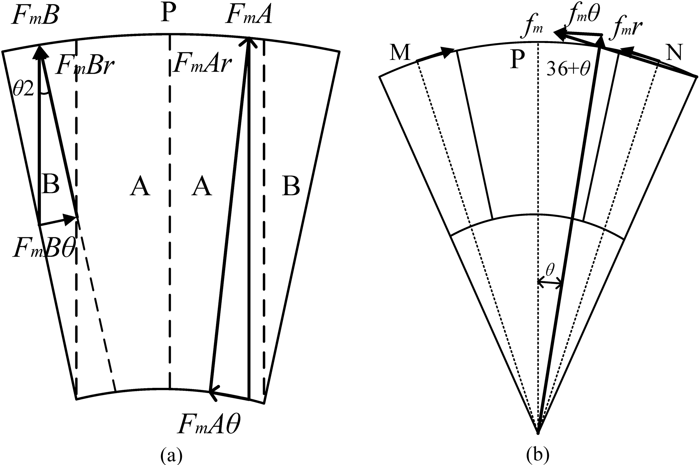
Since a halbach PM array is designed in FSCW-PM machine, the numerical calculation is proposed to guarantee the accuracy when analyzing the magnetization. Magnetization of PMs can be decomposed as a radial and a tangential component. Magnetic loops can be observed not to overlap with each and the split line coincides with the midline of parallel magnetizing PM, as shown in Fig. 10a (the yellow line). The end points of symmetrical lines of tangential PMs only have tangential component, as shown in Fig. 10b. Furthermore, the tangential components between M point and N point of PM can be considered as positive if the components are total outward, otherwise the components are negative. Hence, the parallel, tangential and composit MMF in vector under different halbach array position can be expressed by solutions as:
where
Since the unique structure of halbach array, the MMF is proposed to be sinusoidal in this paper. Equivalent MMF can be obtained as:
where
where
MMF of one PM unit under different 
Equivalent MMF in a slot pitch.
Meanwhile, the equivalent MMF of magnetic circuit in stator branch is related to the running position of rotor, and the MMF of halbach array sinusoidal changes integrated with the angle of halbach array. Figure 12 shows one type of equivalent composit MMF of radial components in a slot pitch, and the MMF can be obtained as:
Lumped parameter magnetic circuit model.
The developed MEC model is shown in Fig. 13. This network topology is constituted by 12 branches according to stator slots. Based on the previous analysis, a dynamic MEC Network model relating to equivalent permeances and magnetic sources can be established by connecting the nodes in magnetic loops. In the model, PM
Calculation and verification
For the MEC Network having
It can be simplified as:
where
The magnetic flux density in teeth can be obtained by the magnetic flux of teeth as:
Considering the magnetic saturation, a nonlinear discrete-time
Flow chart of developing MEC model.
At last, a whole iterative process is developed by replacing the initial magnetic permeability with the new magnetic permeability
Hence, the flux density of the AT
where
The result of the flux density from MEC model of low harmonic design PM machine is plotted in Fig. 15a, and based on of Eq. (27), the dual three-phase back-EMFs is calculated as shown in Fig. 15b. To verify the accuracy of the proposed MEC model for the FSCW-PM machine, the flux density of the AT
Results from MEC and FEM. (a) Flux density of AT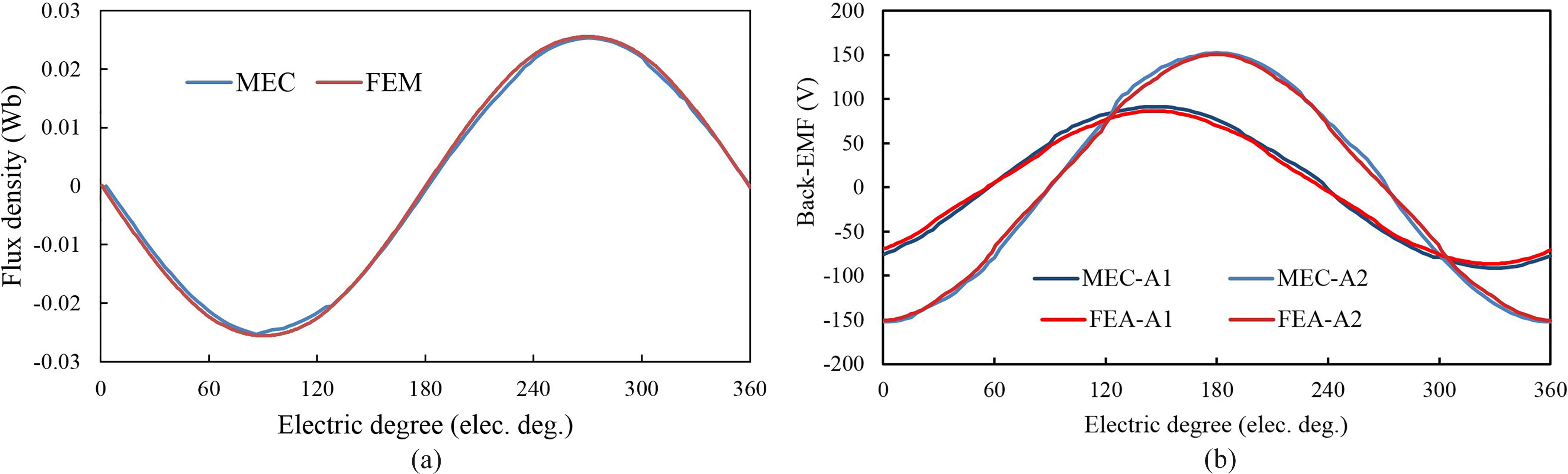
Prototype machine. (a) Stator winding. (b) Experimental platform.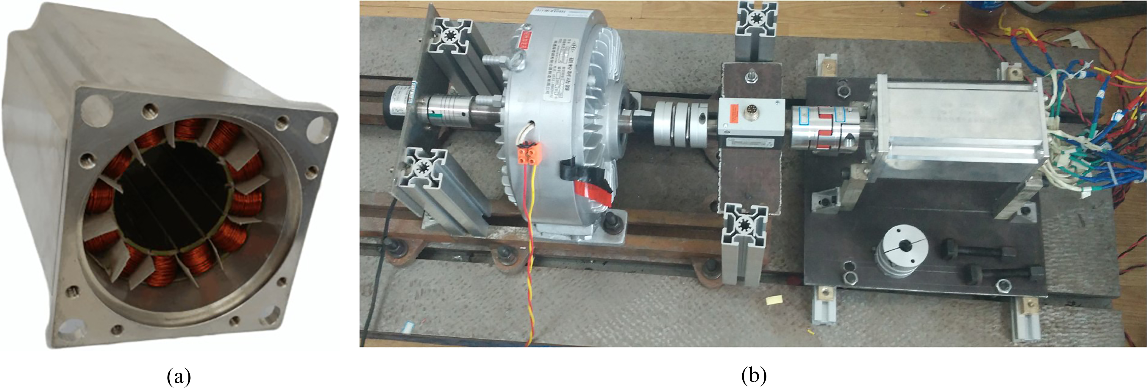
Measured back-EMFs.
However, the flux leakages are neglected in the proposed MEC network. In this low harmonic 12/10 machine, the flux leakages focus on the air-gap from stator to rotor. So, the effective area of air-gap is larger than overlapped area in MEC model, as shown in Fig. 8, but not so much. By developing the model using the overlapped area in Fig. 8, the accurate results show that the flux leakages in air-gap can be neglected, while certainly this neglect brings error in flus density. Especially, in some angle where the flux leakage is more than usual, the calculated flux density may departure more from FEA results, which result in the imperfect equality of flux density between MEC and FEA, same as back-EMF, while those are acceptable, as shown in Fig. 15. Hence, it can be proved that a high accuracy is guaranteed in MEC model based on the agreement of the predicted and measured back-EMFs.
In this paper, a new design for the winding connection has been proposed to reduce MMF harmonics in FSCW-PM machines. Moreover, a model-building method has been introduced to divide and establish equivalent MMF for halbach PM arrays, and developed equivalent permeance for elements in machines, as an alternative analytical approach. Then, a MEC model of low harmonic FSCW-PM machine has been newly built. The electromagnetic performances, e.g., the flux linkage and back-EMF performance, have been obtained from the MEC model, the FEM and the experiments. These results verify that developed MEC model is effective. Also, by adopting the star-delta connection, a number of undesirable harmonics can be eliminated. Thus, the multiple three-phase winding configurations is appropriate in the concentrated windings, while improving winding factors for the working harmonics and reducing higher or lower order MMF harmonics in FSCW-PM machines.
Footnotes
Acknowledgments
This work was supported in part by the National Natural Science Foundation of China (Projects 51477068 and 51422702), by the Qing Lan Project of Jiangsu Province, and by the Priority Academic Program Development of Jiangsu Higher Education Institutions.