



Abstract
The core loss is of great significance in the machine designing and optimization. In the paper, an analytical method for calculating the flux density of surface-mounted permanent magnet synchronous machine is first presented based on the equivalent magnetic circuit and conformal mapping method. The model takes into account the slotting effect and stator saturation. Subsequently, the core loss was calculated by improved Bertotti’s formula in terms of the analytical model of flux density. Finally, experiment and finite element analysis (FEA) are used to validate the accuracy of the proposed analytical method for core loss. It shows that the analytical results for core loss can keep excellent agreement with the experimental results and FEA results. Therefore, the analytical model provides a great potential to the machine designing and optimization.
Keywords
Introduction
The core loss calculation has a significant effect on the surface-mounted permanent magnet (SPM) synchronous machine design and optimization, in order to determine the efficiency. With the wide working range of electrical machine, the core loss calculation at each operating point is complicated and time-consuming due to the nonlinearity of flux density and core loss. Thus, the core loss analysis over the full range of operation is the key technology in the machine designing [1, 2].
In general case, it is difficult to accurately calculate the core loss in the first step of machine designing. In relative literatures, both the analytical and numerical methods have been developed to predict the core loss. In Zhang and Doppelbauer [3] analyzed the numerical calculation of core loss on a novel axial flux machine with segmented-armature-torus topology based on the Bertotti’s formula. The waveform of real flux density was obtained using 3D FEA, and the harmonic flux density waveform in each finite element was obtained by Fourier decomposition. The accurate results can be calculated. However, the computation is complicated and time-consuming. The literatures [4, 5] presented a simplified voltage model based on the superposition of magnetizing and demagnetizing loss component to calculate the core loss within a field orientated controlled brushless AC permanent magnet machine, and test results taken from a concentrated wound brushless AC traction motor are used to validate the technique. However, the simplified voltage model ignored the stator resistance, so the core loss will cause some errors.
The core loss has been greatly influenced by the flux density. Because of the changing flux density at various operating point, the accurate calculation of air gap flux density is of great significance. At present, the air gap flux density is mainly calculated by the numerical and analytical method. The accurate air gap flux density distribution with considering the stator saturation can be calculated by FEA [6]. However, it is time-consuming and complicated. The analytical method mainly includes equivalent magnetic circuit method, conformal mapping (CM) and Fourier’s series method. The literatures [7, 8] analyzed the magnetic characteristics of SPM, and then established the analytical method using the magnetic circuit analysis, which could directly calculate the average air gap flux density and no-load leakage coefficient. However, the accuracy of analytical model is limit without considering the saturation effect of iron material. Later, Han et al. used the magnetic circuit method to model the electric machine with taking into account the stator saturation in [9, 10]. The magnetic circuit method can calculate the average air gap flux density, but it cannot accurately obtain the air gap flux density waveform.
Unlike the magnetic circuit method, CM can accurately predict the air gap flux density waveform. It was firstly used by carter [11] to calculate the carter’s factor in 1926. Then, CM was used to calculate the relative permeance of the air gap [12, 13]. Subsequently, Boughrara et al. used CM to analyze the slotted air gap flux density distribution of inset permanent magnet synchronous motor. Then, the cogging and electromagnetic torque characteristic was obtained by integrating the Maxwell stress tensor. The accuracy of CM was verified by using FEA, but CM doesn’t consider the stator saturation [14, 15]. An extended usage of the method that takes into account the saturation was given in the literatures [16, 17, 18, 19, 20]. The literatures [16, 17] presented the CM to analyze the air gap flux density and complex relative permeance with considering the stator saturation. However, the method doesn’t consider the effect of saturation on the stator permeability. In literature [18], Hafner et al. presented a method to re-parameterize the CM approach by single FE computations so as to consider saturation in the model over a wide operation range of the electrical drive. However, it doesn’t take into account the no-load flux density and it is FE-dependent. The literature [19] modeled the air gap length as a function of the position and level of the air gap flux to consider the saturation effect of induction machine. The saturation effect of stator teeth with induction machine was considered by Ojaghi and Nasiri in the literature [20]. However, it assumed the slot of stator and rotor is open.
The motor whole domain can be divided into several regions in the Fourier’s series method. Then, the equation was solved by the methods of Fourier’s series and separating variables. An exact analytical subdomain model for the open-circuit magnetic field in SPM machines with any pole and slot number combinations was established by Dubas and Espanet [21, 22]. The coefficients of the Fourier’s series can be determined by the boundary conditions. Then the air gap flux density and cogging torque was obtained. Zhu et al. applied the scalar magnetic potential as the solved variable of equation to solve the no-load flux density in the literatures [23, 24], and applied the vector magnetic potential as the solved variables to analyze the no-load flux density in the literatures [25, 26]. All above the methods of Fourior’s series analyze the air gap flux density without considering the stator saturation.
Each analytical method for calculating the air gap flux density and core loss has its own properties. Therefore, the novelty of the paper is to propose an accurate analytical method of calculating magnetic field based on the equivalent magnetic circuit and conformal mapping, in order to improve the efficiency and accuracy of magnetic field. The stator permeability can be obtained by equivalent magnetic circuit method, and the equivalent magnetic circuit method takes into account magnetic saturation. Then, the permeability has been applied to conformal mapping to analyze the magnetic field distribution. On the basis of the analytical model of air gap flux density, the core loss is calculated by the improved Bertotti theory.
This paper is organized as follows: Section 2 introduces the theory of CM, which maps the model of SPM to the canonical domain. The stator and rotor permeance is calculated by using the equivalent magnetic circuit in Section 3. Section 4 analyzes the analytical model for calculating the core loss with saturated and unsaturated condition. The calculation results, discussion and verification of core loss are presented in Section 5. Section 6 gives the conclusion.
Conformal mapping method
Motor design parameters
Motor design parameters
CM is an analytical and numerical method for calculating the air gap flux density of SPM. The basic theory of method is to map the operating field of complicated and unknown air gap magnetic field into a domain of simple and known magnetic field distribution. Then the unknown magnetic field can be solved by the correspondence relationship. Finally, the air gap flux density distribution of motor can be obtained. In the paper, three CMs are applied to reach the simple and known annular domain.
In the paper, SPM has been chosen to demonstrate the CM method. The model of the machine structure is shown in Fig. 1, and the basic machine parameters are listed in Table 1. In the SPM, a three phase, star connected, double-layer distributed winding construction is used. The laminated core packs are made of SiFe (DW310-35), and the magnets are formed from the rare earth-cobalt (XG160/120) grade with
The analysis model of SPM.
The motor model in 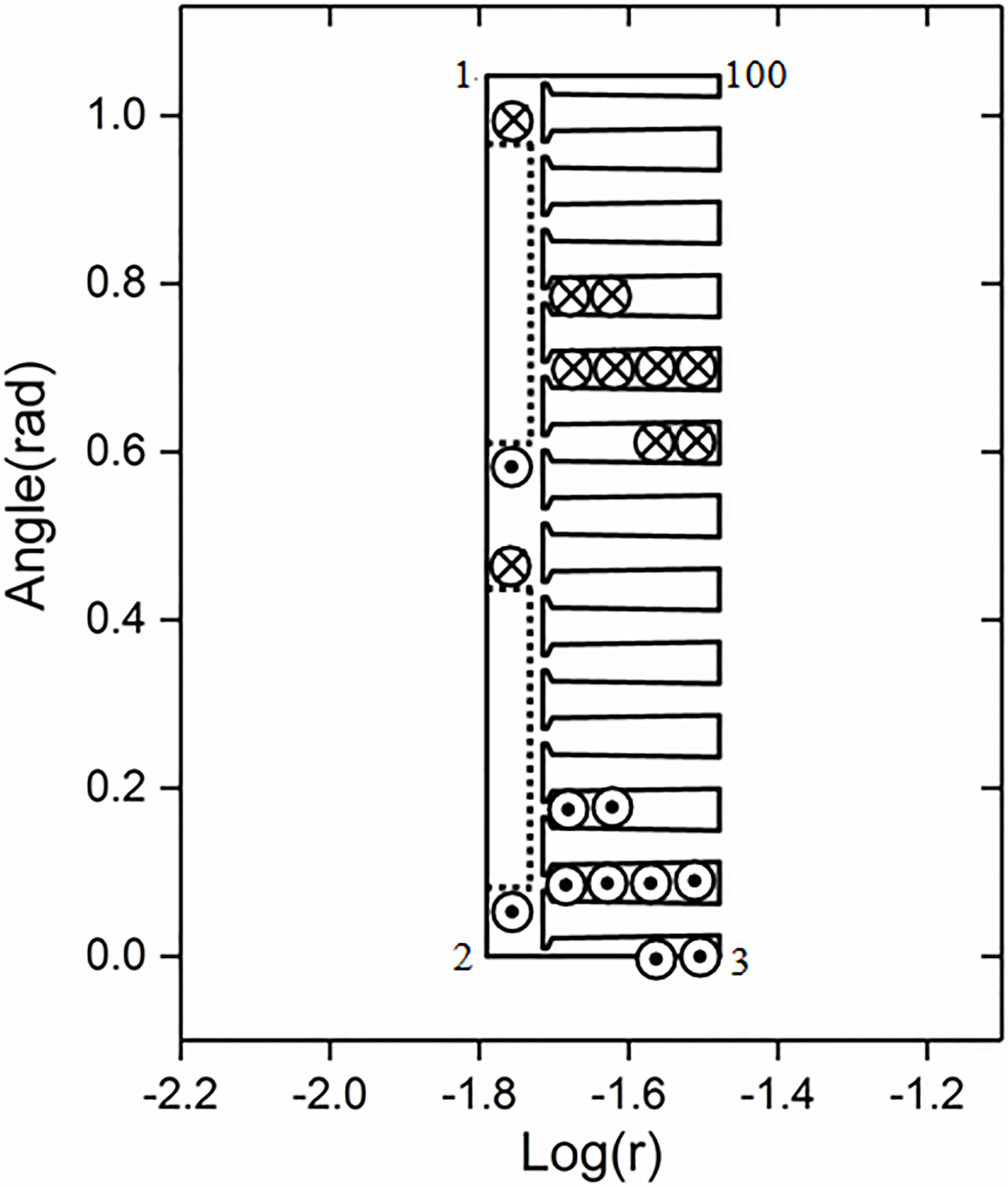
Let the motor geometry shown in the Fig. 1 be
The second CM is the Schwarz-Christoffel mapping. The SC mapping maps one canonical domain into the interior (exterior) of the respective polygon, and the SC Toolbox provides a library of command-line function and a graphical user interface to obtain the canonical rectangle in the
The canonical rectangle in the 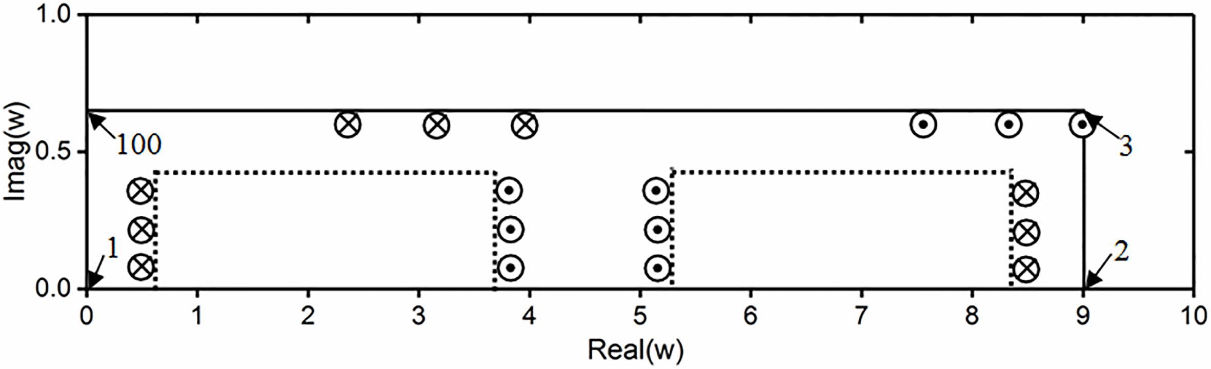
The third CM maps the canonical rectangle in the
The annular domain in the 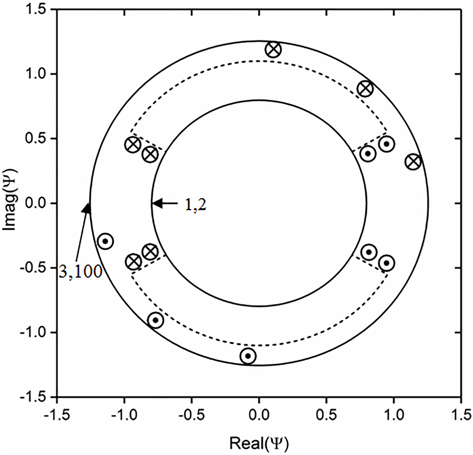
Where,
The annular domain in the
The canonical annular domain in the 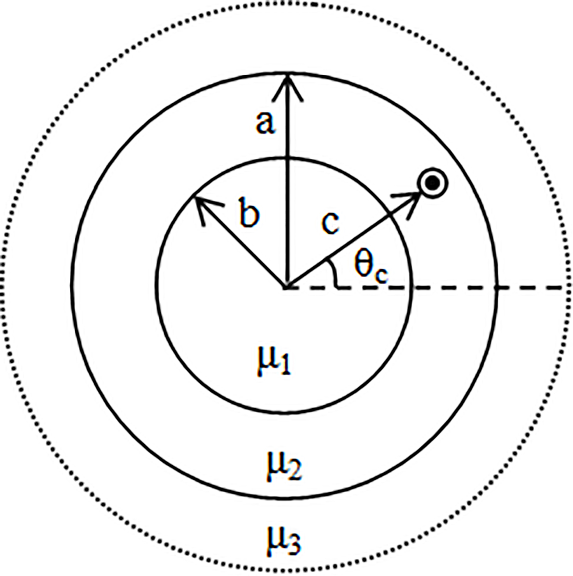
Where
Based on the scalar magnetic potential, the air gap flux density due to the PM and winding currents can be calculated by
Conformal maps preserve the scalar magnetic potential from
Where
The saturation effect has great influence on the properties of the stator composed by silicon steel sheet. The stator permeability decreases seriously with the increase of saturation degree. Meanwhile, it can be seen from Eq. (5) that the stator permeability has a significant effect to the magnetic field. However, CM doesn’t consider the influence of stator saturation on the permeability. In the paper, the stator permeability was analyzed by the equivalent magnetic circuit method.
The equivalent magnetic circuit theorem
The flux of SPM can be divided into three sections. It includes the flux source for one magnet pole, the air gap flux for one magnet pole and the leakage flux which cross through one magnet pole and two magnet poles. Given the flux distribution and the Ohm’s law equivalent of magnetic circuit, the equivalent magnetic circuit is shown in Fig. 6a.
The simplifying magnetic circuit model. (a) The equivalent magnetic circuit; (b) The simplifying magnetic circuit model by simplifying (a); (c) The simplified magnetic circuit model by simplifying (b); (d) The consequently magnetic circuit model.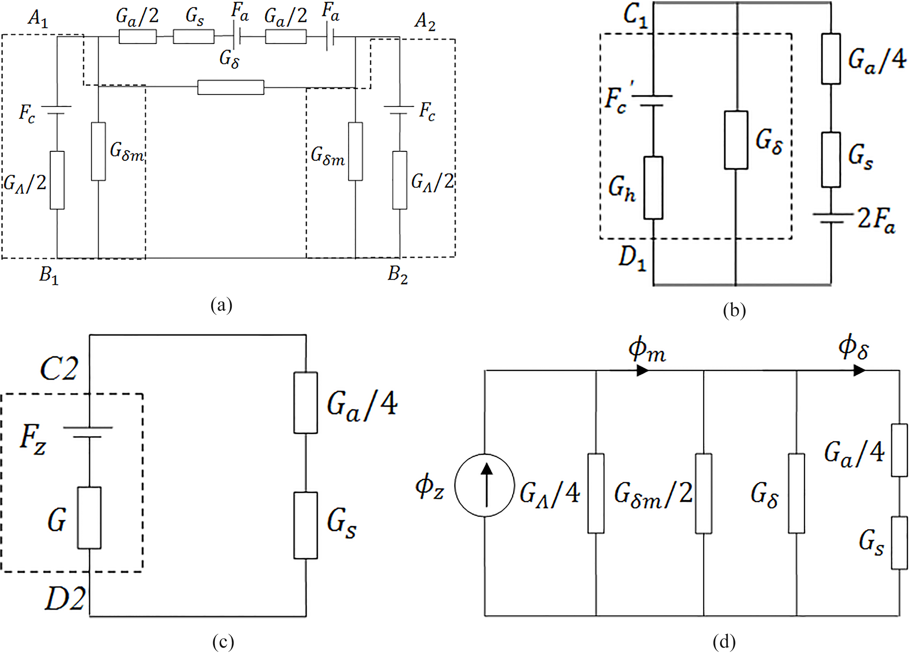
The variables of Fig. 6a are defined as follows:
Where:
Where,
The equivalent magnetic circuit has been established without considering the permeance of the stator and rotor before, but the silicon steel sheet permeability down to a very small value when the motor magnetic field arrivals to saturation. Ignoring the silicon steel sheet permeance will produce the errors. Therefore, stator and rotor permeance is considered as the series connection of stator teeth, yoke and rotor permeance in the paper, which is calculated as:
Where
Where,
Then thevenin theorem is applied to simplify the two ports A1-B1 and A2-B2 in the circle marked with dotted lines. Only one port need to solve because of the same parameters of two ports. The simplified magnetic circuit is presented and shown in Fig. 6b.
Where
Similarly, thevenin theorem is applied to simplify the port C1-D1 once more. Figure 6c shows the simplified magnetic circuit.
Where
Where,
Finally, the nortons theorem is applied to the port C2-D2. The consequently magnetic circuit model is shown in Fig. 6(d). The short circuit flux of port C2-D2 is:
The results of average air gap flux density.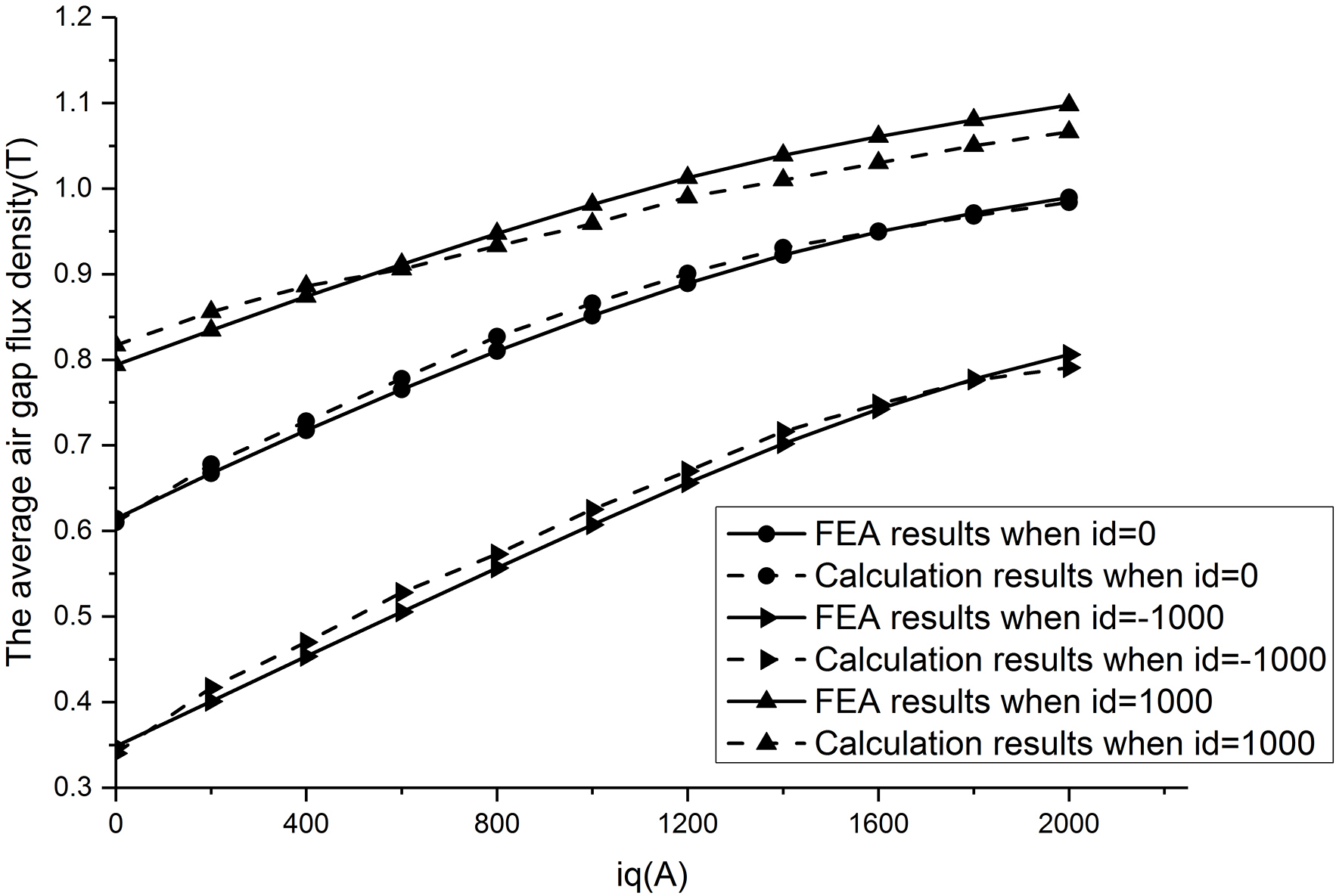
It can be seen from Fig. 6d that the total magnetic flux of PM and winding current flows through the PM permeance and leakage permeance, and the air gap flux is obtained. Then the air gap flux density can be calculated by the air gap flux and the surface area of air gap. That is,
In order to verify the accuracy of equivalent magnetic circuit method, FEA is used. Figure 7 shows the calculation results and FEA results of average air gap flux density when
The basic magnetization curve of silicon steel sheet.
The magnetization curve of silicon steel sheet is shown in Fig. 8. Based on the magnetization curve, the magnetic intensity can be obtained with the known flux density, so the permeability can be defined as
Where
The calculation results of stator and rotor permeability.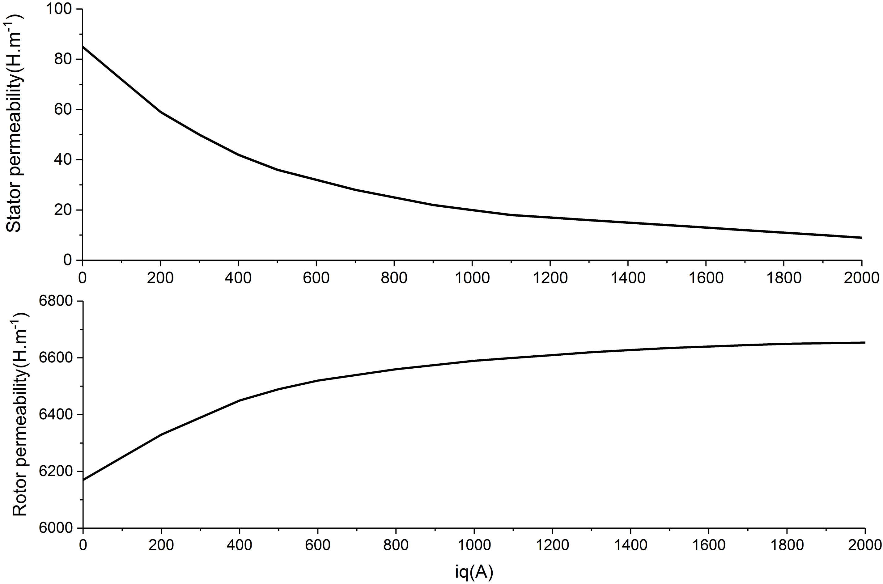
According to the Eq. (16), the permeability in various loads can be obtained. Because the flux is mainly influenced by the minimum permeability, the value of stator permeability is the minimum permeability of stator teeth and yoke. Figure 9 is the calculation results of stator and rotor permeability with the variety of q axis current, and the d axis current is 1000 A. The stator permeability drops quickly when the q axis current increases. However, it is difficult to reach saturation for the rotor because of the large size, so its flux density increases with the increasing q axis current. Therefore, the rotor permeability has a small increase.
The air gap flux density analysis
The analytical model of air gap flux density is established based on the CM and equivalent magnetic circuit method .The calculation step is: 1) the permeability of stator and rotor corresponding to the load currents is calculated by the equivalent magnetic circuit method; 2) based on the permeability, the air gap flux density can be analyzed by CM with considering the stator saturation.
According to the two steps, the air gap flux density in the position of
The calculation results and FEA results of air gap flux density.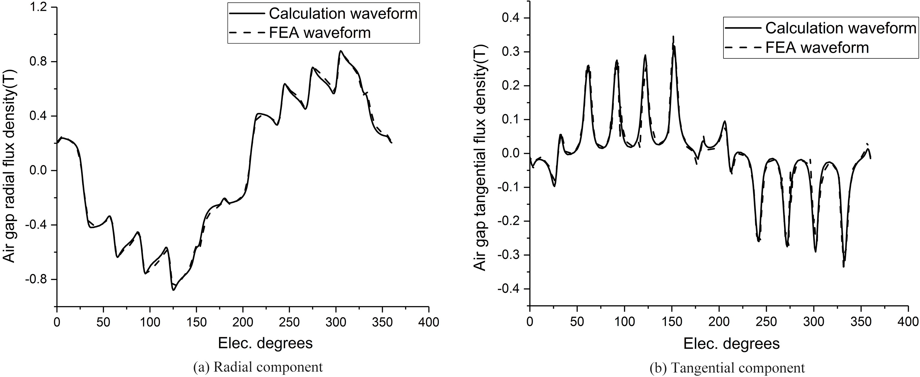
The calculation results and FEA results of air gap flux density when the current is
The calculation results and FEA results of air gap flux density. 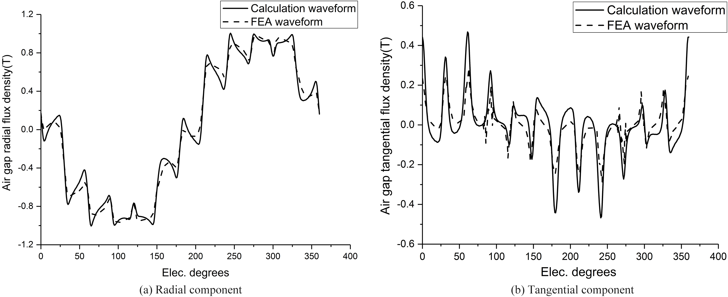
The changing flux density determined by winding current and rotor rotation can produce the core loss. Generally, the Bertotti model is widely applied to calculate the core loss [27]. According to the Bertotti model and the theory of producing the core loss, the core loss is separated into the hysteresis loss, eddy current loss and excess loss.
The hysteresis loss is produced by the frictional interactions among the magnetic domains of iron material when the electromagnetic field varies. The theory of eddy current loss is the eddy current in the iron material induced by the changing flux density because of the winding current and rotation of rotor. The excess loss is produced in anisotropic iron material. Most research hold that it is related with the magnetic domains. Based on the principle of three loss model, the Bertotti’s formula is:
Where,
It is assumed in the Bertotti’s formula that the real waveform of flux density is far from Sinusoidal because of the changing flux density determined by winding current and rotation of rotor. All the fundamental and harmonic flux density produces the eddy current loss and excess loss. Therefore, the eddy current loss can be expressed in the form of time-domain due to the formation theory of eddy current loss. The eddy current loss can be defined as:
According to the core loss performances of iron materials, the coefficient of hysteresis loss, the eddy current loss and excess loss can be determined with the curve fitting method. The core loss at various operating point can be calculated by the Bertotti’s formula. The flowchart for calculating core loss is shown in the Fig. 12.
The flowchart for calculating core loss.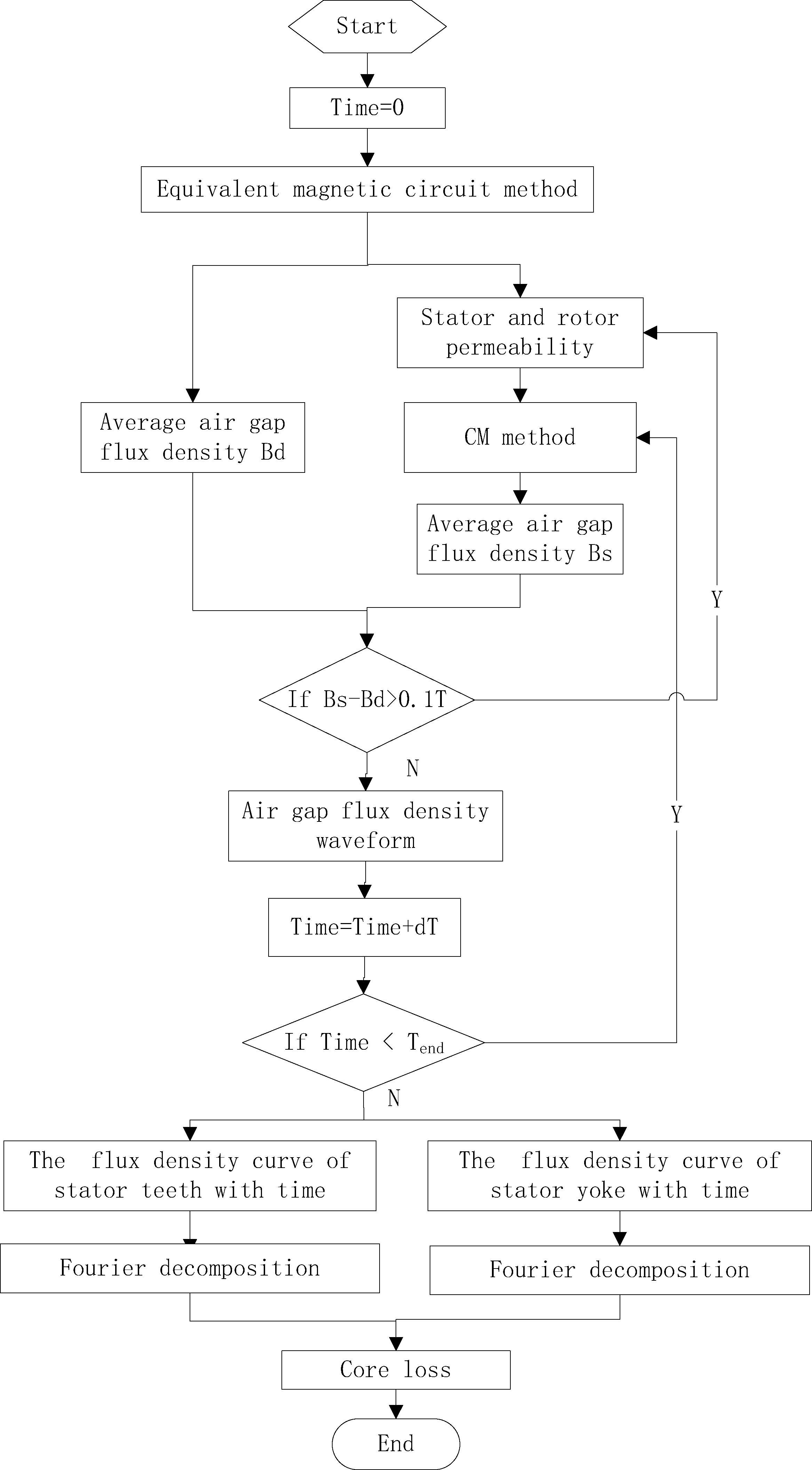
The core loss analysis
Based on the air gap flux density analysis, the flux density distribution of stator teeth and yoke at different moments can be obtained. Then, the fundamental and harmonic amplitude can be calculated by the Fourier decomposition of the stator teeth and yoke flux density. Finally, the stator core loss can be obtained by the Eqs (18) and (19).
The flux density of stator teeth. 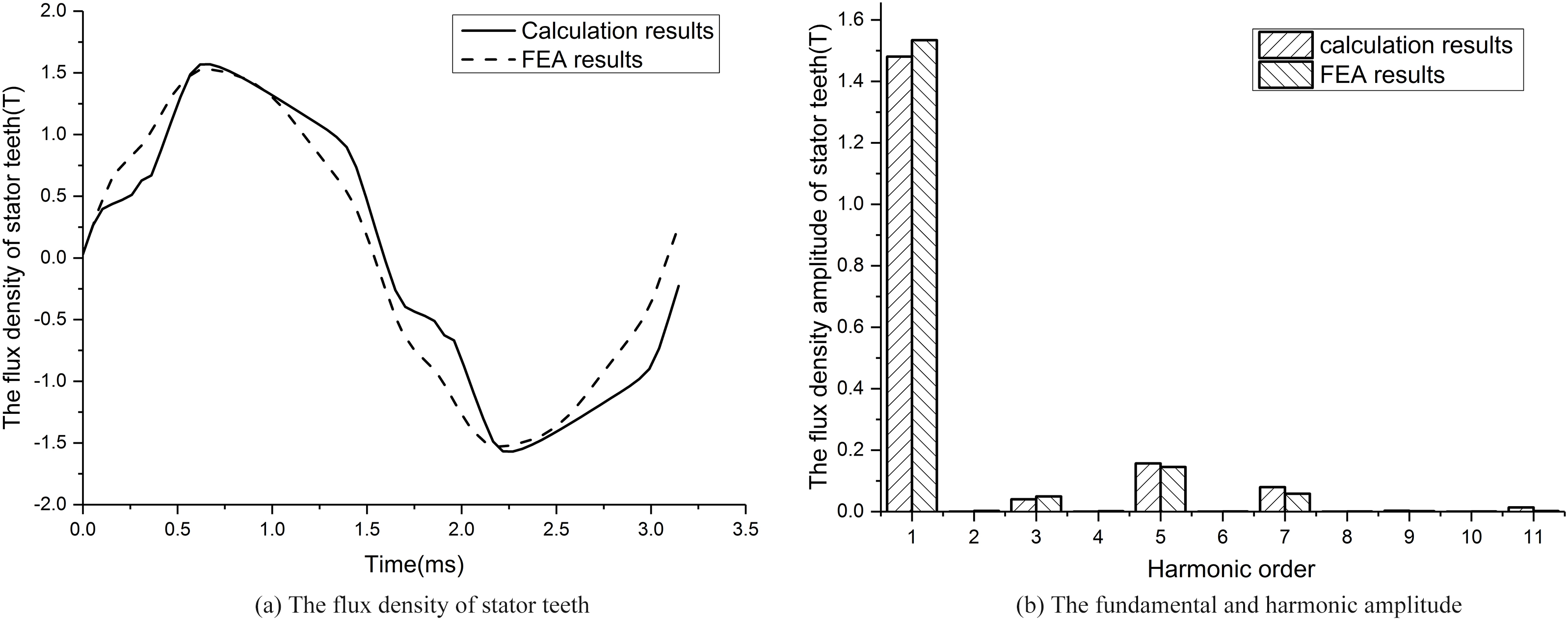
Figure 13a shows the analytical and FEA results of stator teeth flux density in one complete electric period when the winding current is
The flux density of stator yoke. 
Because the analytical calculation of stator teeth and yoke are not take into account the pole-to-pole leakage flux and its tangential flux density, there are some errors between the analytical results and FEA results, and the differences is below than 5%. It also illustrates the teeth harmonic amplitude of third and fifth is much more than the corresponding harmonic amplitude of stator yoke due to the slotting effect.
According to the analytical method shown in the Fig. 12, the core loss of external characteristic operating point is calculated. The external characteristic curve of SPM divides into constant torque and constant power area, as shown in the Fig. 15.
The load current of external characteristic can be obtained by the motor pharos relationship, as listed in Table 2. It can be seen that the phase current remain unchanged in the constant torque area (0
The load current of external characteristic operating point
The external characteristic curve of SPM.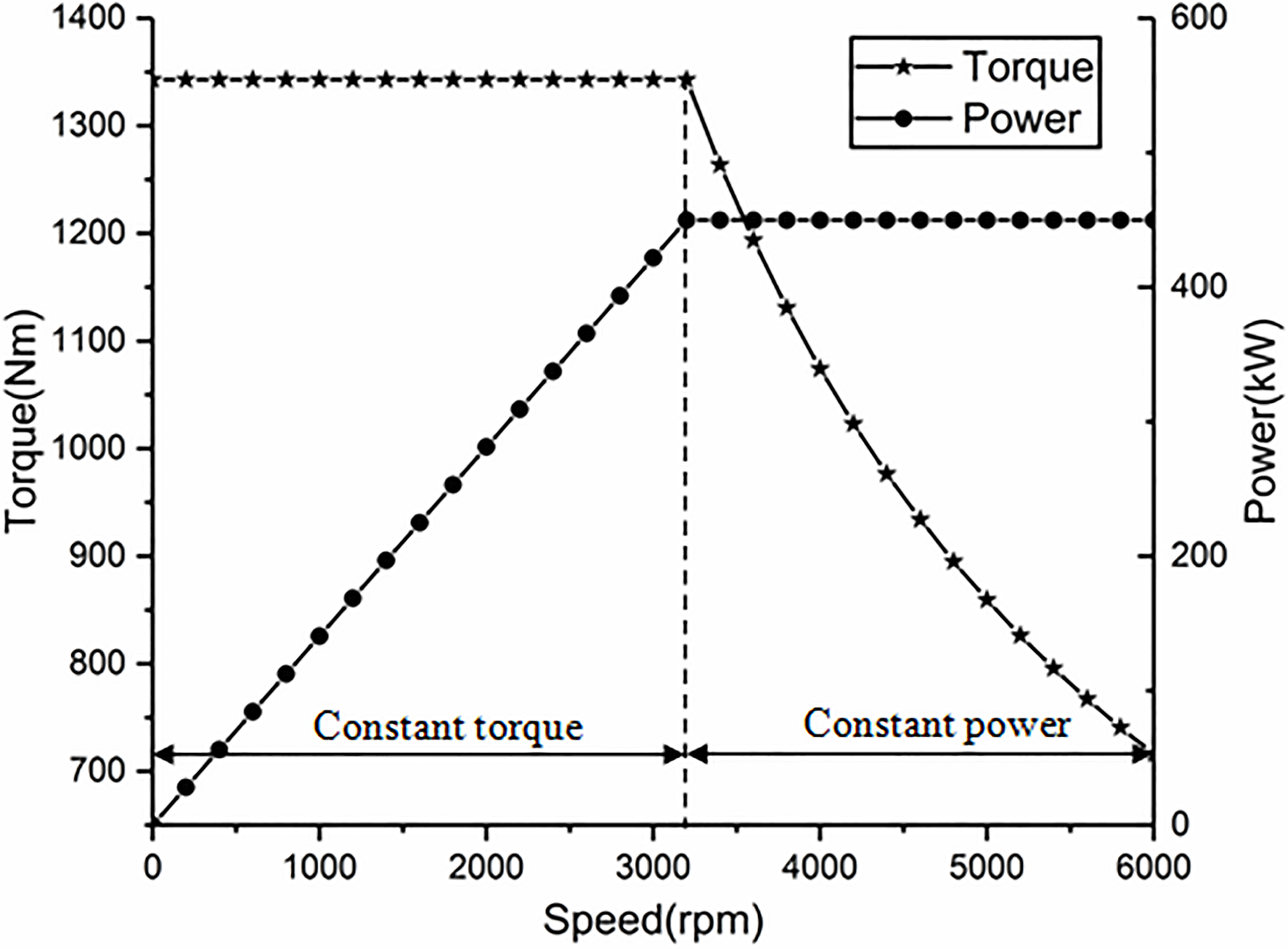
The core loss of the external characteristic operating point. 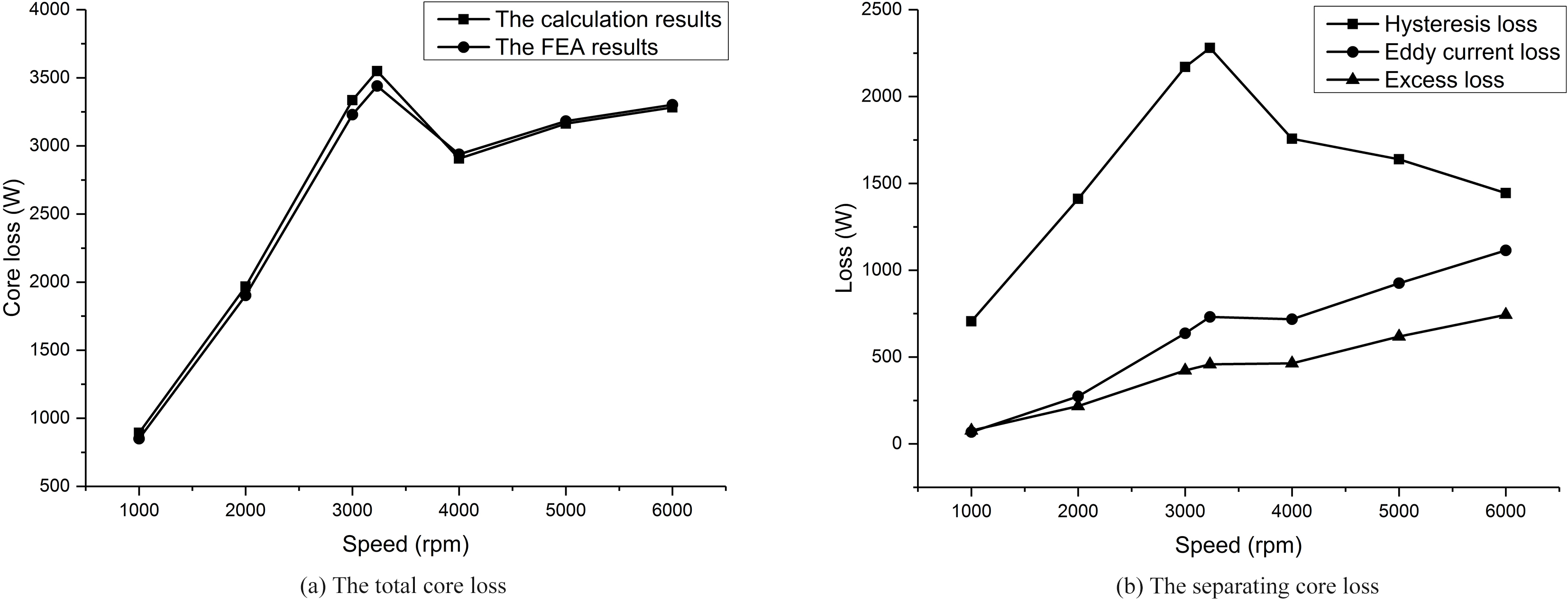
Base on the operating point listed in Table 2, the core loss distribution can be obtained by the analytical flowchart shown in the Fig. 12. Figure 16 shows the total core loss and the separating core loss (hysteresis loss, eddy current loss and excess loss) of the external characteristic operating point. In the constant torque area, the flux density of stator teeth and yoke remain unchanged because of the same phase current. The core loss is mainly determined by the motor speed, so the core loss increases with the increases of speed. All the separating loss increases in the constant torque area, and most of the core loss is the hysteresis loss. In the constant power area, the flux density of stator teeth and yoke become smaller because of the effect of d axis demagnetize current. However, the core loss cannot decrease a lot due to the increasing speed. At the time, the hysteresis loss drops due to the decrease of flux density. The eddy current loss and excess loss remain increase because of the increasing of flux density harmonic amplitude and speed. In addition, the rising speed of eddy current loss is higher than that of excess loss.
The dimension of experimental motor.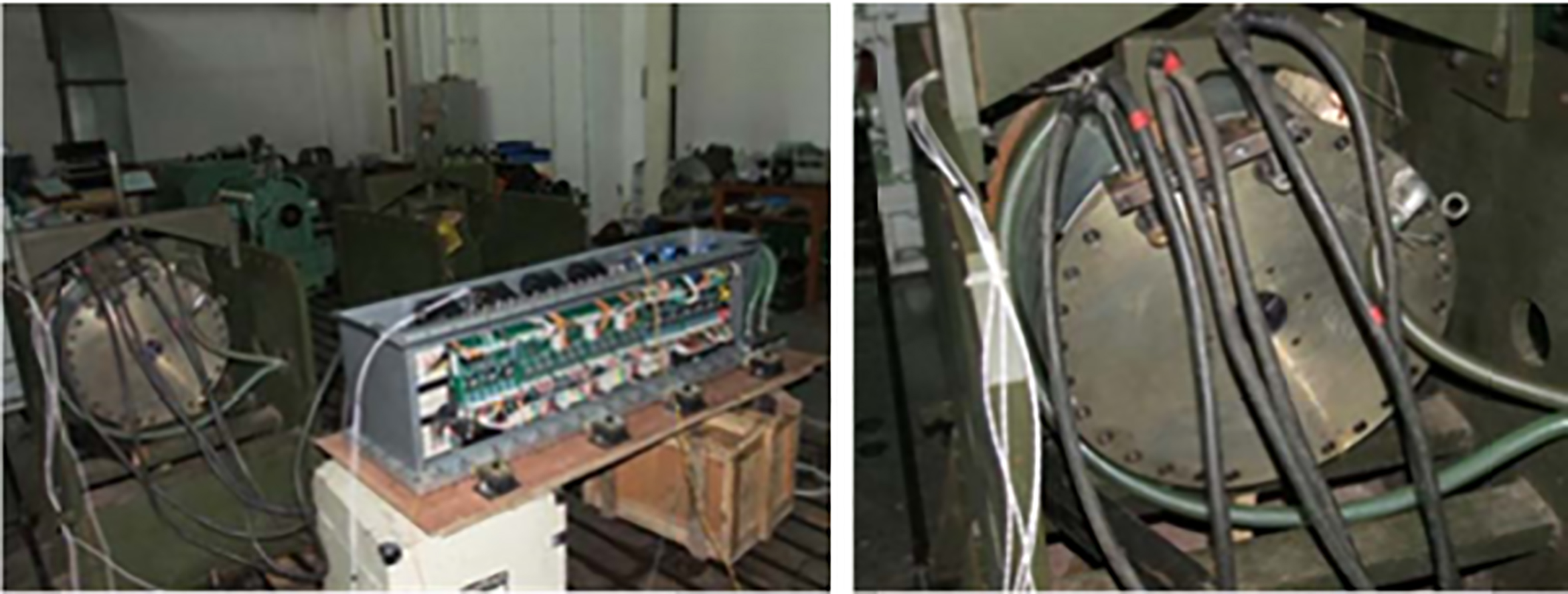
The calculation, FEA and experimental results of core loss.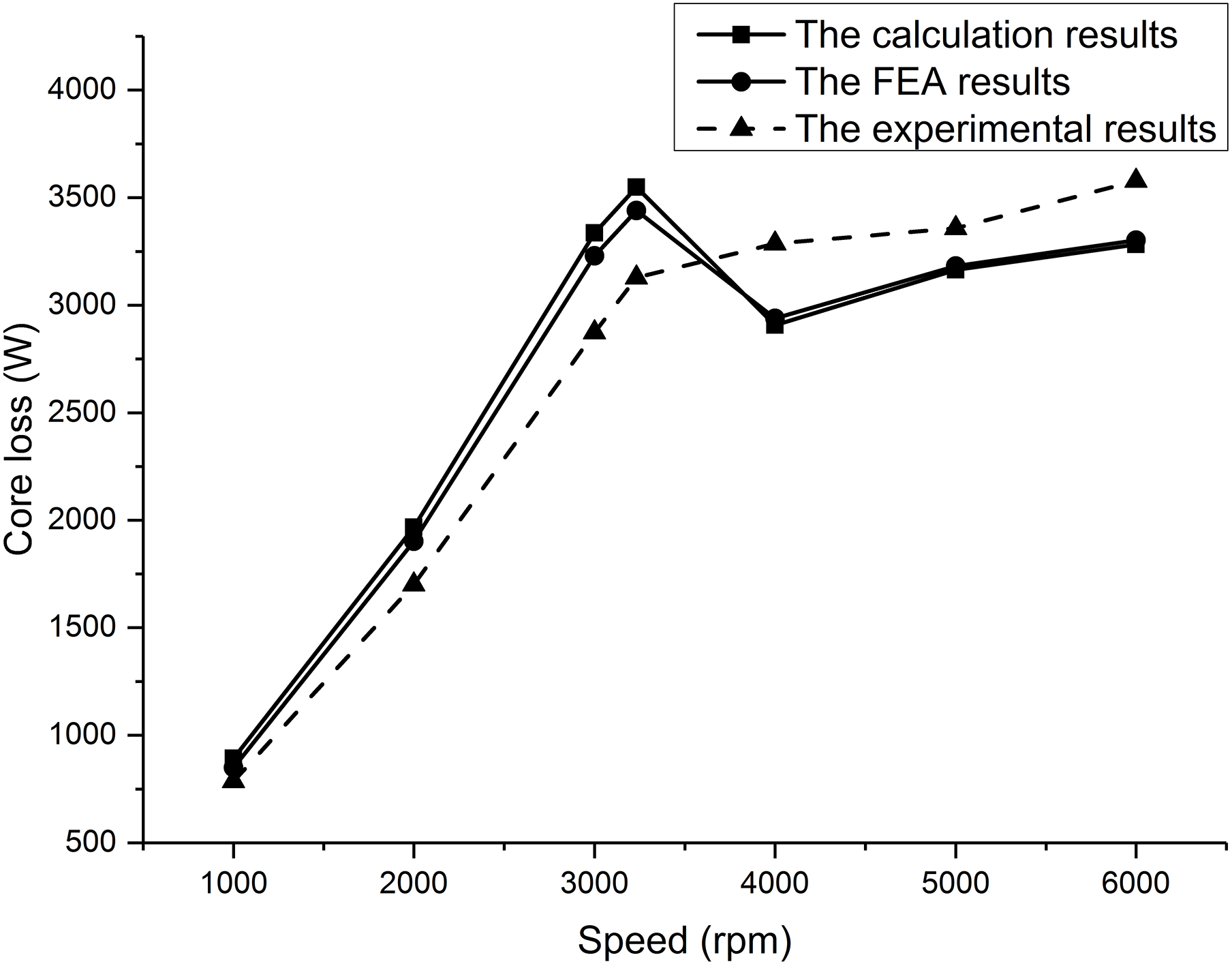
In order to verify the accuracy of the analytical method, experiment was performed on the SPM. The rated power of experimental machine is 450 kW. The core loss tested by the experiment is obtained by core loss separation of test data. The dimension of experimental motor is shown in the Fig. 17. The core loss obtained by analytical method, FEA and experiment is respectively shown in the Fig. 18.
From Fig. 18, the core loss obtained by experiment could keep consistence with the FEA and calculation results in the external characteristic operating point of SPM. However, the experimental value is slightly smaller than the FEA and calculation results in the constant torque area, and the experimental value is slightly larger than the FEA and calculation results in the constant power area. Therefore, the analytical model can be applied to calculate the core loss.
Conclusions
The paper has described a new analytical method for calculating the core loss of saturated SPM using a model based on the equivalent magnetic circuit method and CM. The stator permeability can be obtained by equivalent magnetic circuit method, and the equivalent magnetic circuit method takes into account magnetic saturation. Then, the permeability has been applied to conformal mapping to analyze the magnetic field.
Based on the analytical model, the radial and tangential component of air gap flux density due to the PM magnetization and winding currents can be separately calculated. Regardless of whether the stator material is saturated or unsaturated, the analytical results of air gap flux density keep consistency well with the FEA results. Hence the relations between the d-q axis currents and air gap flux density can be easily analyzed by the analytical method.
Moreover, compared with the FEA results and experimental results of core loss, the analytical results show very excellent agreement. Therefore, the analytical method could be applied to calculate the core loss, so it is helpful for the optimization and designing of the electric machine.
Footnotes
Acknowledgments
This work is supported by the National Natural Science Foundation of China (Grant no. 51677005).