
Abstract
Location and topology of substation grounding grids are critical for its regular tests and safe operation. Schematic drawing of the grounding grid is prone to getting lost or damaged. As excavation is costly and time consuming, locating substation grounding grid is important. This paper proposes a novel method to locate substation grounding grid by using the derivative method and the concept of locating a geometrical object in polar coordinate system. Due to rectangular structure of grounding grid, its location can also be determined from the location of its single branch. Simulation and experimental results verify that the proposed method is feasible and accurate to solve the inverse problem regarding the location of substation grounding grid.
Introduction
Grounding grid is the main component of a grounding system. It ensures the safety of power equipment, operators and stable operation of a power system by providing a low resistance path to the surge currents [1, 2, 3, 4, 5]. Grounding grid consists of horizontal conductors making square meshes. It is buried about 0.7 m to 1 m below the earth surface. The conductors of grounding grid are typically made up of steel, galvanized steel or copper with a spacing of 3 m to 7 m being of the most common. The only access points to grounding grid from earth surface are the vertical conductors connected to the grounding grid [6].
Corrosion of metals is a natural phenomenon in which the metals are oxidized. As the grounding grid is also made up of metal or metal alloy, soil corrosion causes grounding grid to corrode or even break the conductors in severe cases. Corroded or broken grounding grid is inefficient. Since the grounding grid is hidden (buried in soil), regular diagnostic tests are conducted to monitor its status [7, 8].
Fault diagnosis of grounding grid has been the focus of researchers over time. The research development in this field involves measuring the surface potential difference considering the frequency characteristics of soil and grounding grid conductors [9]. Some have used the electric circuit theory and mesh-work method that measures the resistance between two ground lead wires [10, 11]. But these methods are inaccurate because changes in ground resistances are small even if the grounding grid is broken. Some studies employ transient electromagnetic (TEM) imaging technique to locate break points in grounding grid by measuring the apparent electrical resistivity of grounding conductors, but these studies have failed to deliver the accurate assessment of a breakpoint and absent conductor [3, 12].
Fault diagnosis of the grounding grid requires its complete topology [13, 14]. Although every grounding grid built is associated by drawing schematic describing its complete topology, but because of human error the drawing can get spoil or suffer the loss. Research on topology detection of grounding grid is extremely limited. [6] introduced the concept of derivative method to measure the topology of grounding grid. Position of peaks resulting from odd derivative of surface magnetic flux intensity corresponds to the location of buried conductors. [13] used the concept of regret and [15] directly reconstructed the topology of grounding grid from the distribution characteristics of surface magnetic flux density. Furthermore, [16] employ transient electromagnetic method (TEM) based on the smoke ring concept to detect grounding grid topology. However, the aforementioned methods have assumed the grounding grid location parallel along the wall of substation. This makes the grounding grid location parallel in the earth plane. Yet, in practice the grounding grid may not be located completely parallel in the plane of earth. In such scenario, currently employed methods for topology detection fails to deliver accurate results.
Demonstrating the technique of [6] for conductor located at angle 
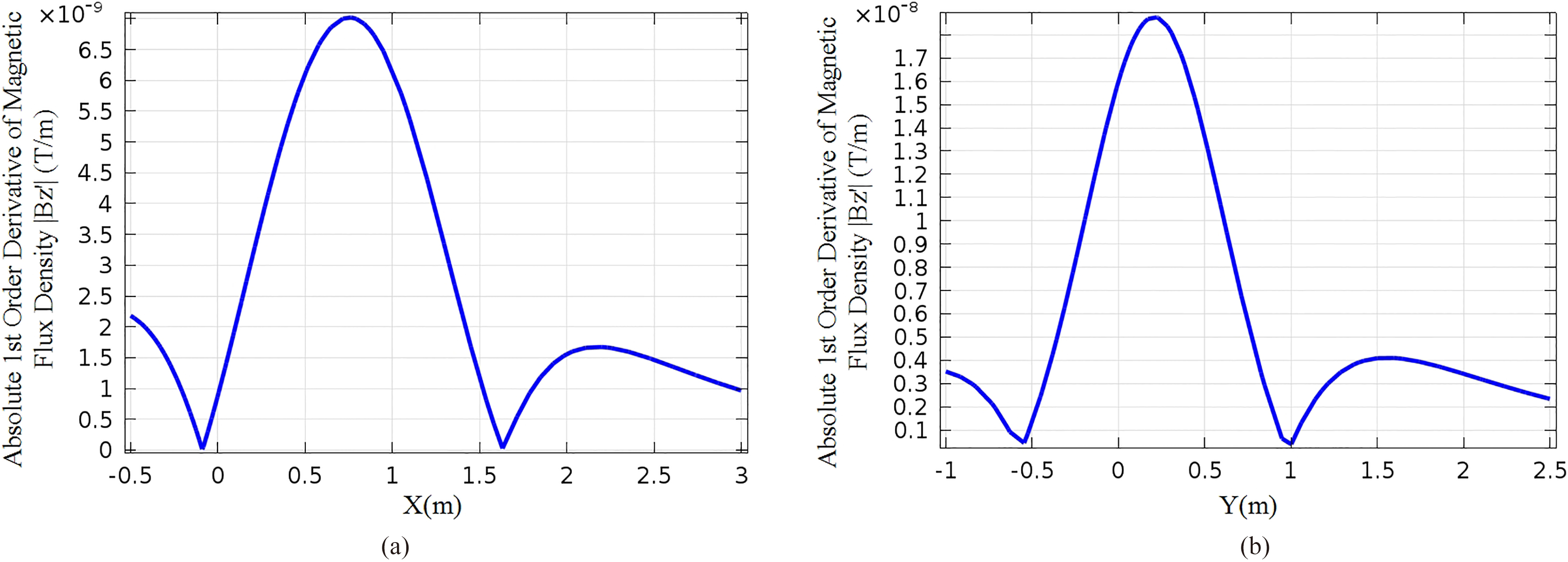
Figure 1 depicts the scenario of current carrying conductor buried at some angle in the earth plane. Employing the method presented in [6], the location determined does not coincide with the location of buried conductor. Figure 2 represents the results achieved by employing the technique of [6]. According to Fig. 2, the buried conductor is either located at
Locating grounding grid is a problem that needs the attention of researchers. In this paper, we proposes a novel technique based on derivative method and the concept of locating geometrical object in polar plane. First, direct current is injected in grounding grid through vertical conductor. The magnetic flux density received at the earth surface is subjected to derivative on circle centered at vertical conductor. The position of magnetic flux gradient peaks along the circumference of circle coincides with the location of grounding grid. To test the effectiveness of the proposed method, lab tests are conducted. The results of the lab tests are in close agreement with the model study. Finally, our proposed work overcomes the limitation present in the methods proposed by [6, 13, 15, 16] (assumption of grounding grid location) for topology detection of grounding grid. Moreover, our method is also applicable to locate any angled branch present in the grounding grid.
In practical installations, pipelines are buried along the grounding grid in substation. These pipelines are made up of conductive material such as steel, etc. As our proposed method utilizes direct current, there will be no effect of the underground pipeline on our proposed method. Therefore, in this paper the presence of pipeline is not taken into consideration.
The remaining paper is organized as follows: Section 2 elaborates the problem, Section 3 illustrates the methodology, Sections 4 and 5 present testing and simulation results, and Section 6 presents the conclusions.
Forward problem
Using the method of Electromagnetic Induction the forward problem features the known value of the injected current
The forward problem is illustrated using a 3
Illustration of forward problem: 3 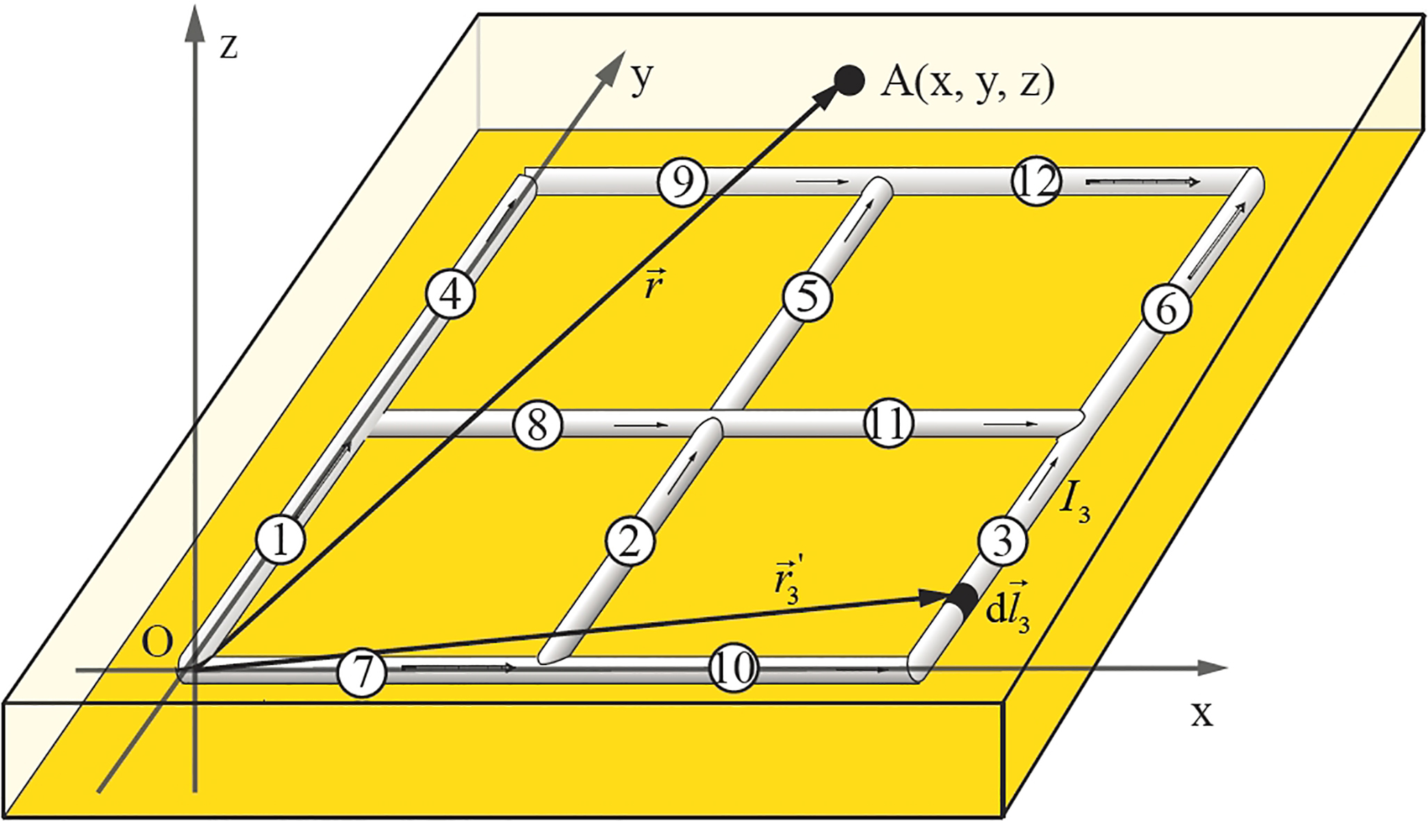
According to Biot-Savart’s law the magnetic flux density at a point A(x,y,z) from a branch carrying current
where
Integrating Eq. (1) for branch 3 along its length as shown in Fig. 3 gives the magnetic flux density due to branch 3:
As Fig. 3 shows a grounding grid with twelve branches, the magnetic flux density at point A(x,y,z) due to the grounding grid is the sum of magnetic flux densities from individual branches:
In case of inverse problem the injected current
To solve the inverse problem regarding the location of substation grounding grid, the proposed method takes the electromagnetic and derivative method into account. Current is injected in the grounding grid through vertical conductor and derivative of surface magnetic flux density is taken on circle. Location of branches obtained from the derivative determines the location of grounding grid.
In polar coordinate system a point in space is located with respect to its distance from the pole (
Method illustration for a single current carrying conductor
In this section the proposed method is demonstrated by analysing a single current carrying conductor of infinite length. Figure 4 illustrates the conductor placed along y-axis at depth
Infinitely long current carrying conductor located along y-axis and buried at depth 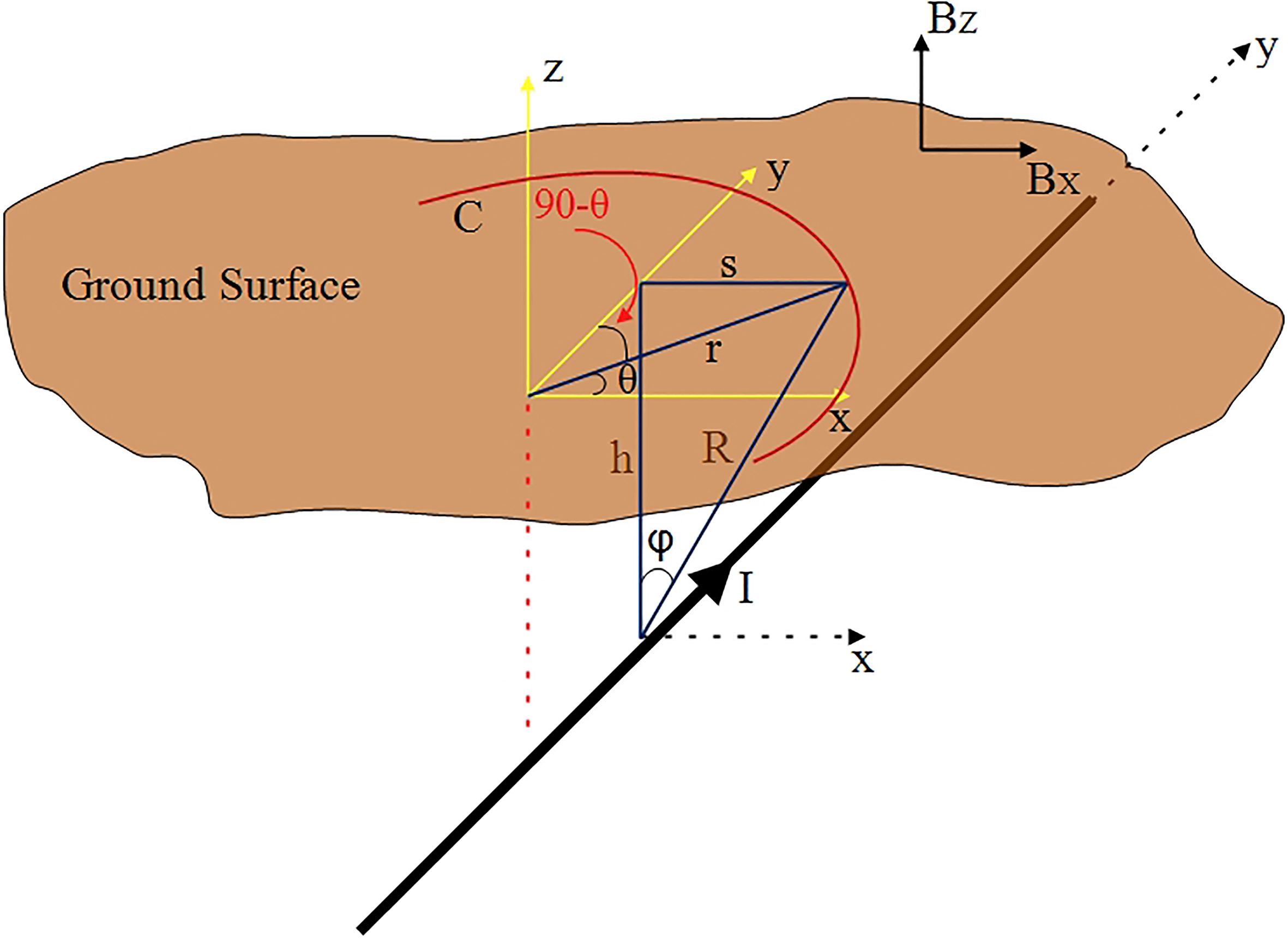
According to Ampere’s law, the magnetic flux density
To obtain the z-component of
Putting Eqs (5)–(7) in Eq. (4),
Derivative of Eq. (8) on circle C is expressed as:
here
Analysing Eq. (9),
Absolute 1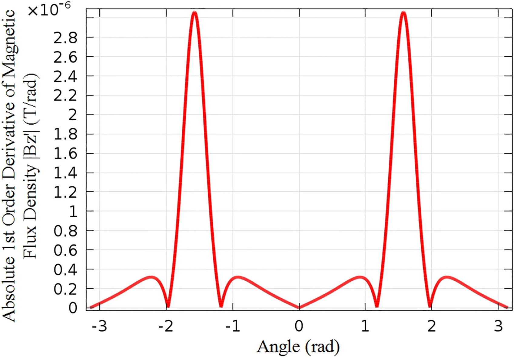
Simulation model: Grounding grid is placed parallel in the assumed xy-plane. To obey the rules of polar coordinate system, 
The model accounted for simulation is shown in Fig. 6 which is a 3
1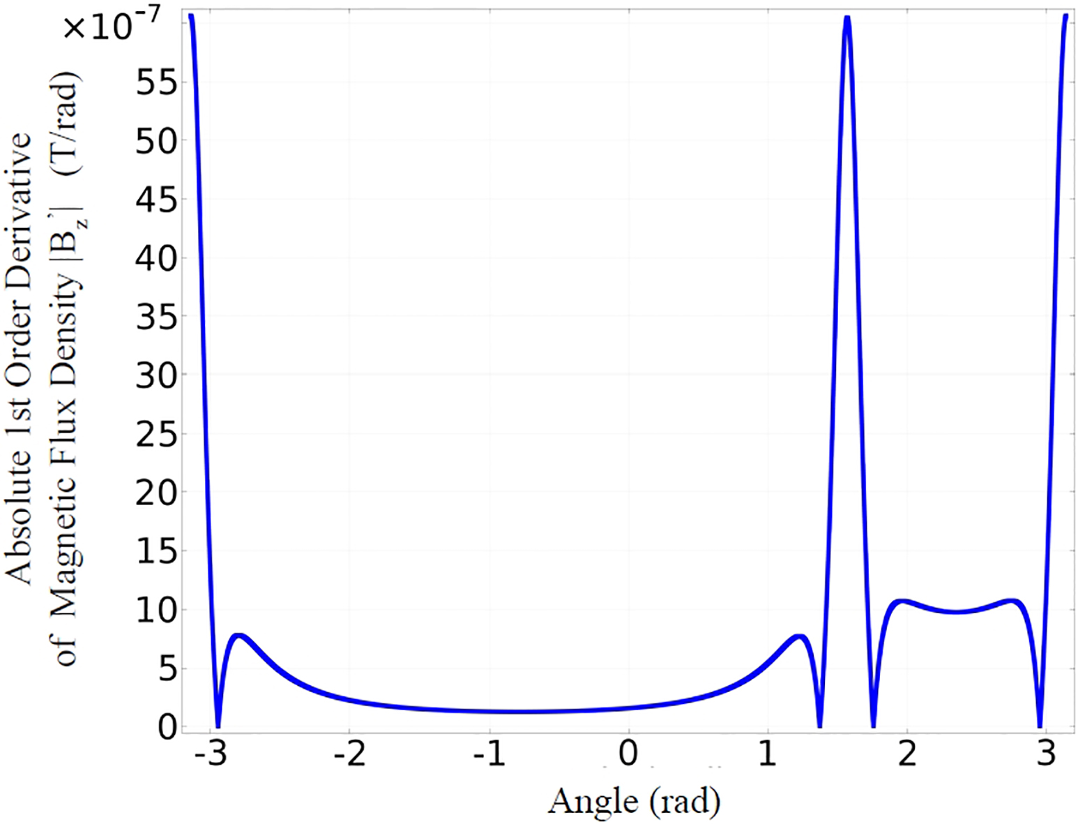
Vertical conductor A is taken as origin for circles
1
Figure 7 depicts result of derivative on
From the above observation it is concluded that the radius of circle should be chosen such that it does not include the branches which are not connected below the pole point. In practical grounding grid the length of a branch varies from 3 m to 7 m, and thus the radius of the circle must be constrained to be between 0 m and 3 m.
To verify the accuracy of the proposed method lab test is conducted using the Hall Effect Probe method. A CH-Hall Model 3600 Guass/Tesla meter is used to measure the magnetic flux density in mT. The probe of the device is moved in x, y, and z direction by a 3D control motor that has a space range of 400 mm
Lab experiment. (a) Experimental model: 3 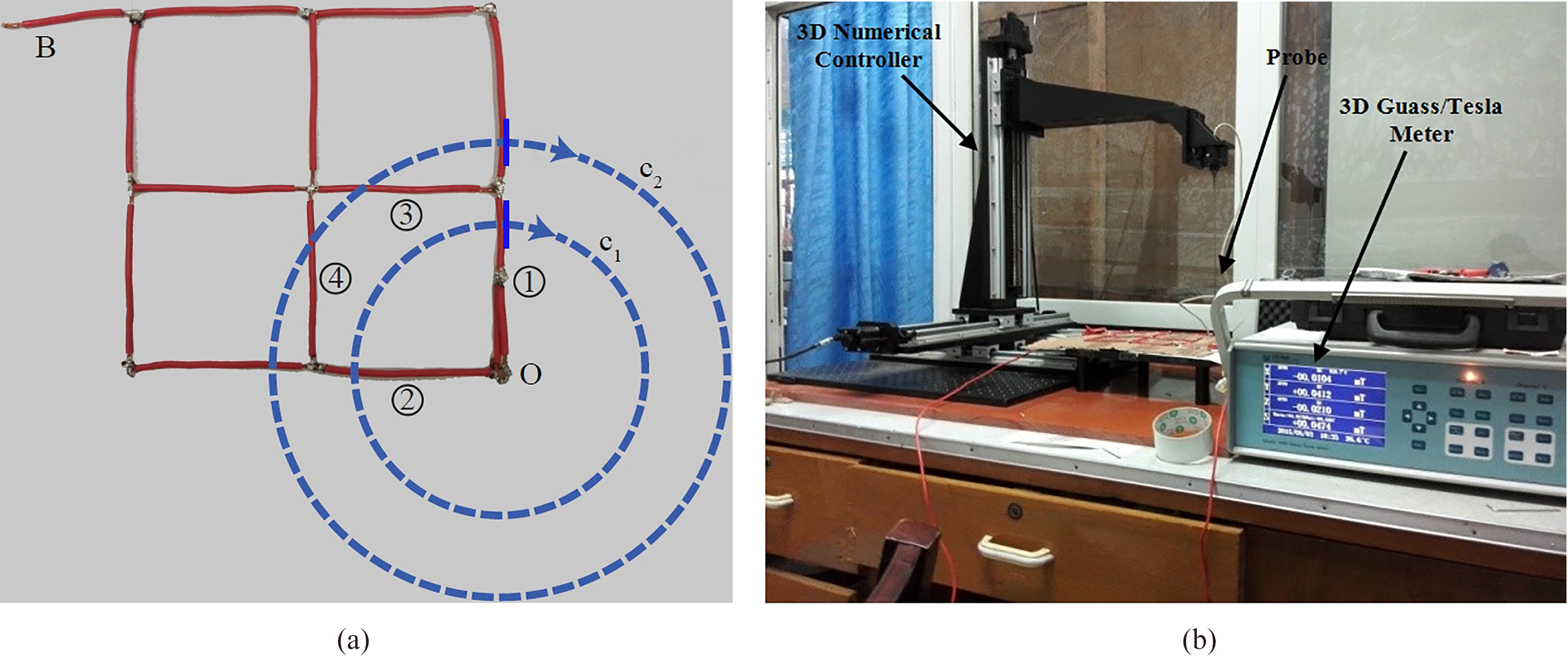
The experimental model for the lab test is shown in Fig. 9a. The model is a 3
Measurements are taken along circles
The order of measurement of
Taking into account the influence of background noise, the measured magnetic flux density fluctuates along the circle, and so is the differential of magnetic flux density. Discrete Fourier transformation (DFT) of simulation result shows that, most of the information is in low frequency signal, while DFT of lab test result shows a considerable disturbance of high frequency signal, which must be removed. In order to filter the result, DFT is used to convert the time-domain signal into frequency-domain signal, and remove the high frequency part. Subsequently, with the inverse discrete Fourier transformation, the discrete signal is recovered (the low-pass filtered signal). Compared with the graph of original data, the graph of filtered data is smoother, but the height of peaks also decreases. Compared to the filtered data, the effect of branches 3 and 4 is more notable in the original data. The original signal indicates the location of branches more accurately while the graph of filtered data is smoother.
Experimental results. (a) Derivative of magnetic flux density along c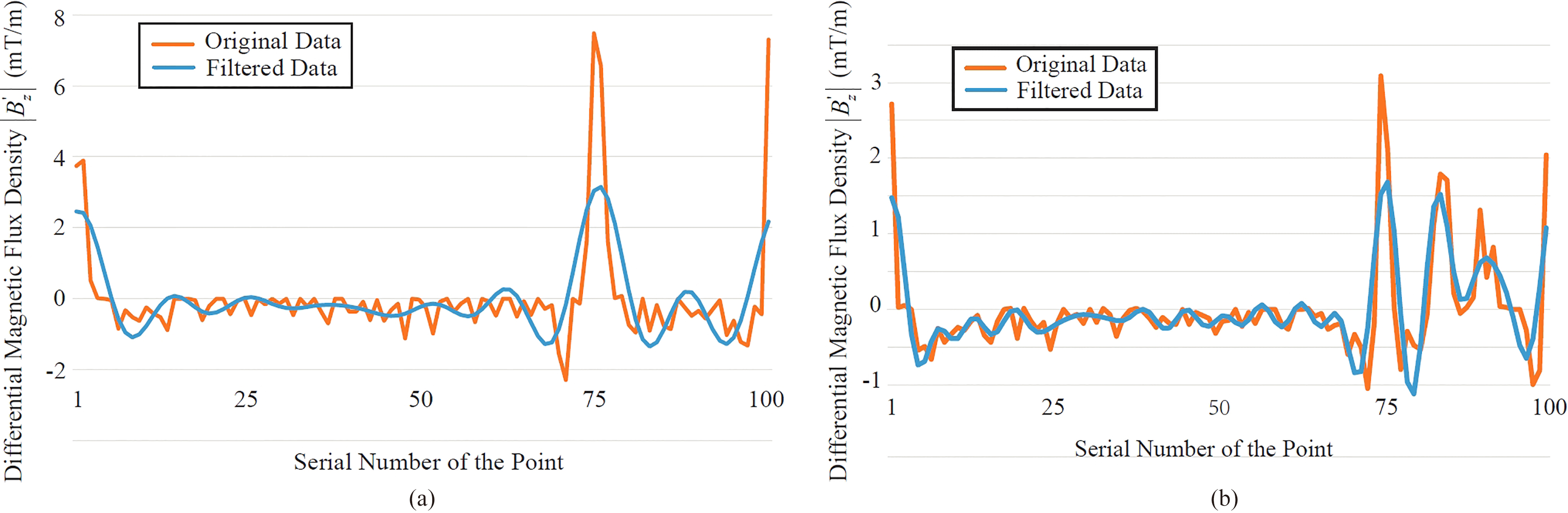
Figure 10 illustrates the result of differential magnetic flux density along
Schematic drawing of substation grounding grid is prone to getting lost or damaged. Consequently there is a need for topology detection which is an ultimate requirement for grounding grid fault diagnosis. Location of grounding grid is the first step towards topology detection. As excavation is costly and time consuming, this paper proposed a novel technique based on derivative method to solve the inverse problem of locating substation grounding grid in case of drawing loss. Derivative of surface magnetic flux density on circle locates branches connected below the center of circle. As grounding grid has rectangular shape, location of its single branch can determine its location. In practical grounding grid the mesh spacing varies between 3 m to 7 m. Radius of the circle is constrained between 0 m to 3 m. Based on the simulation results and lab experiments it is concluded that derivative method is a feasible technique to locate substation grounding grid without excavation.
Footnotes
Acknowledgments
This work is supported by the Laboratory of Electromagnetic Imaging and Applications, the College of Electrical Engineering, Chongqing University, Chongqing, 440004, China.