
Abstract
This paper presents a method for specifying the magnetizing current of the transformers operating with different submagnetizing of DC flux and for different values of supply voltage (flux density in the core). The theoretical method of calculating of magnetizing currents has been developed. The computation and corresponding measurements were performed for single phase and three phase, three and five legs transformer cores. The influence of magnetization characteristics on the shape of instantaneous current value was investigated. The results obtained were used to determine the peak values of flux density in certain parts of the magnetic circuit. This has a significant impact on precisely determine vibroacoustic parameters and losses in particular sections of the magnetic circuit of transformers.
Introduction
Typical power transformer operates mostly with sinusoidal flux in the core. The operation of special transformers is often connected with the DC component of current in one of the windings which cannot be transformed to the primary side. The DC ampereturns remain not compensated and consequently submagnetise unidirectionally the core. The value of the DC component of the magnetic flux density depends not only on the DC component of the amperturns and the characteristics of the magnetization but also on the value of the AC flux density component (supply voltage). Submagnetizing of the core with a DC component provides a significant increase of the amplitude of magnetizing current, increase the maximum value of flux density and consequently the deterioration of its magnetic and vibroacoustic parameters [1, 3, 6].
For the analysis of this phenomenon the theoretical calculations and experimental investigations of transformer models were carried out.
Measuring system
For examination of the influence of submagnetizing on the magnetizing current of transformer cores for the flow of DC flux through magnetic circuit (single phase and three phase, five legs transformer), the investigations were conducted in a specially developed measuring systems presented on Fig. 1 [3]. Two identical square model cores (folded from the belts of the grain oriented transformer sheet about dimensions of 600
For analysis of this phenomenon for three-phase systems the experimental investigations were done with a three-phase, three-leg transformer [3]. In this case, measurements were made, connecting one of the winding in open triangle and supplying with DC current (for the flow of DC flux like yoke flux). A special measuring system has also been developed for testing three-phase transformers, when one of the columns is submagnetized [3].
The diagram of the measuring set (with submagnetizing of DC current).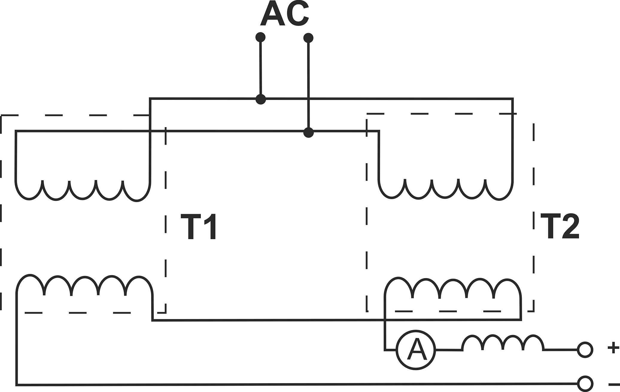
In this case, two identical transformers have three windings. The first windings of each transformer were supplied with AC current. The second winding of one of the phases of each transformer were joined inversely, and supplied with DC current submagnetising and saturating the tested legs [3]. In this case, the flux of the DC component flows through the other two columns of the transformer and the generated DC magnetic flux closes up through a path with low reluctance, therefore the value of this flux is quite high, for relatively small submagnetizing current. This effect depends not much on, which column is submagnetized, the middle one or one of the side columns.
The magnetizing current of the transformer results from the maximum flux density in the core, ie the supply voltage and the shape of the magnetization characteristic. Due to the hysteresis loop, the shape of the current is asymmetrical and the peak value increases sharply with saturation. Figure 2 shows the shape of the magnetizing current recorded in the measuring system of Fig. 1 for flux density equal to 1.03, 1.49 and 1.72 T.
The shape of the magnetizing current for flux density equal to 1.03, 1.49 and 1.72 T.
The change of the maximum value of the magnetizing current as a function of flux density.
Figure 3 shows the measured change of the maximum value of the magnetizing current as a function of flux density. This characteristic allows to determine the value of maximum flux density in transformer operating with submagnetizing.
Using the waveforms of Fig. 2 and the sinusoidal supply voltage (for selected flux density), the shape of the magnetization curves was calculated and shown in Fig. 4 (for flux density equal 1.43, 1.6 and 1.72 T). As can be seen in Fig. 4, the width of the hysteresis loop increases with the increase of flux density.
The hysteresis loop calculated for flux density of 1.72 T was approximated by polynomial, using the spline function.
The calculated shape of the hysteresis loop for various values of flux density.
Chracteristics of the current as a function of induction obtained according to assumed approximation functions.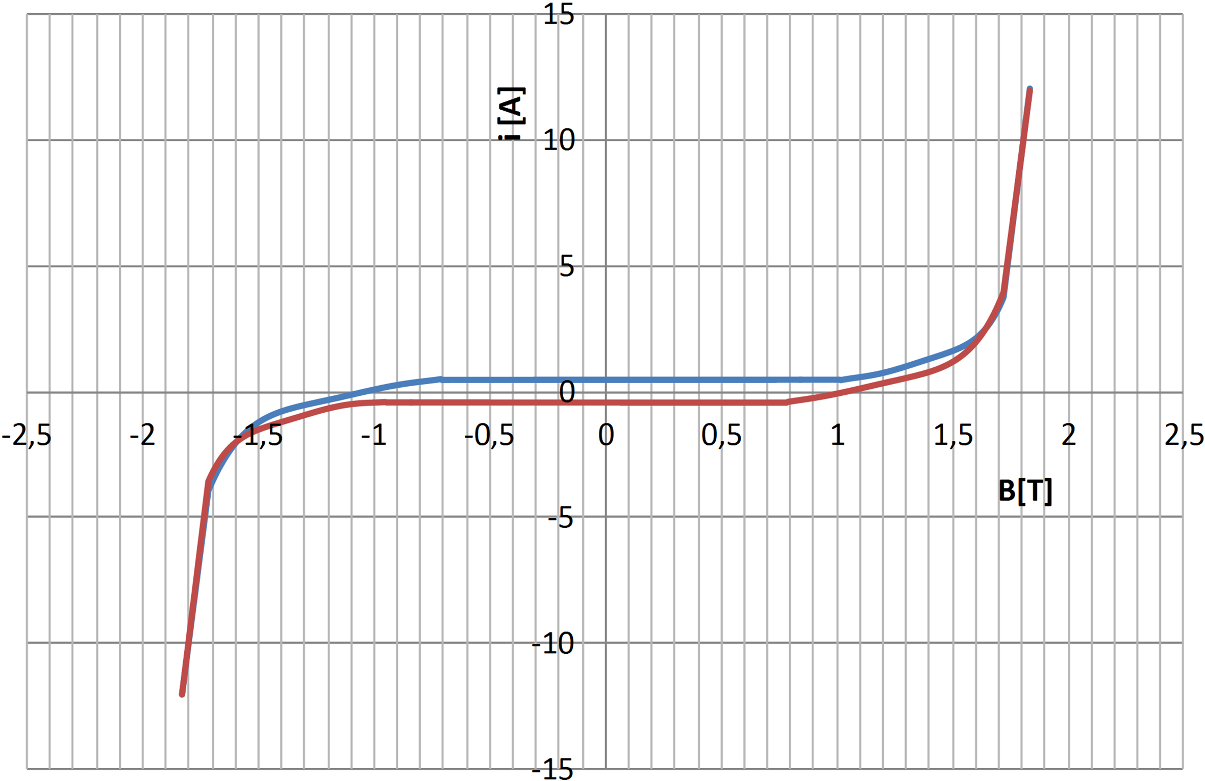
Obtained after approximation, the characteristics of the change of current as a function of flux density are given in Fig. 5. This characteristic allows to calculate the instantaneous shape of the magnetizing current for different flux density values above 1.4 T.
Figure 6 shows the calculated magnetizing current for the core of Fig. 1 based on the characteristics of Fig. 5 for flux density of 1.83T. Calculations of magnetizing currents according to the characteristics of Fig. 5 for induction below 1.4 T are burdened with more errors. For good accuracy in a wide range of flux density changes several characteristics, as shown in Fig. 5, should be determined (for example, for induction of 0.9 T, 1.4 T and 1.7 T).
The calculations presented in the article were made using own procedures developed in the Visual Basic language.
Magnetizing current calculated from the characteristics of Fig. 5 for flux density of 1.83 T.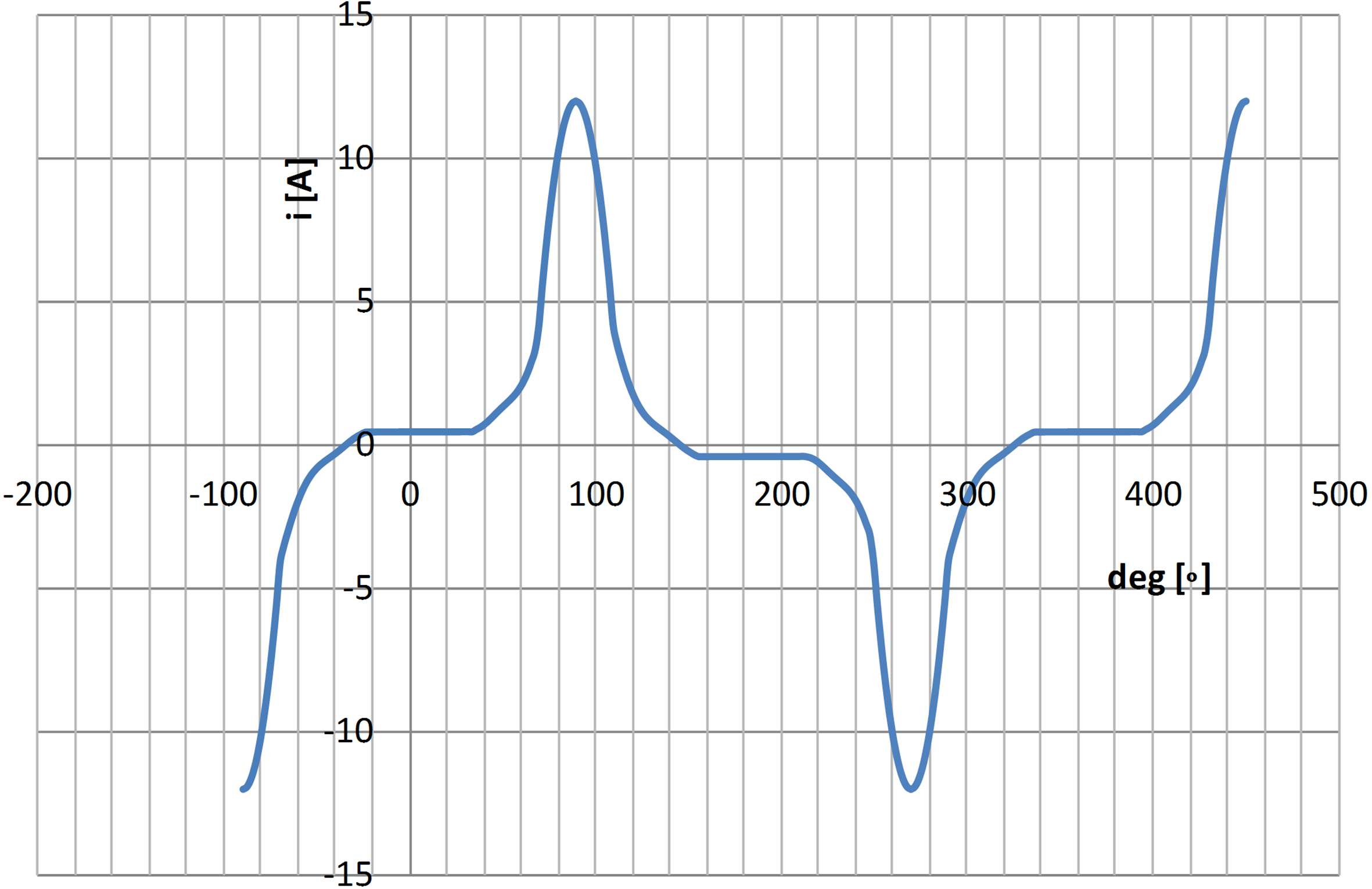
Magnetizing curves of various sheet metals.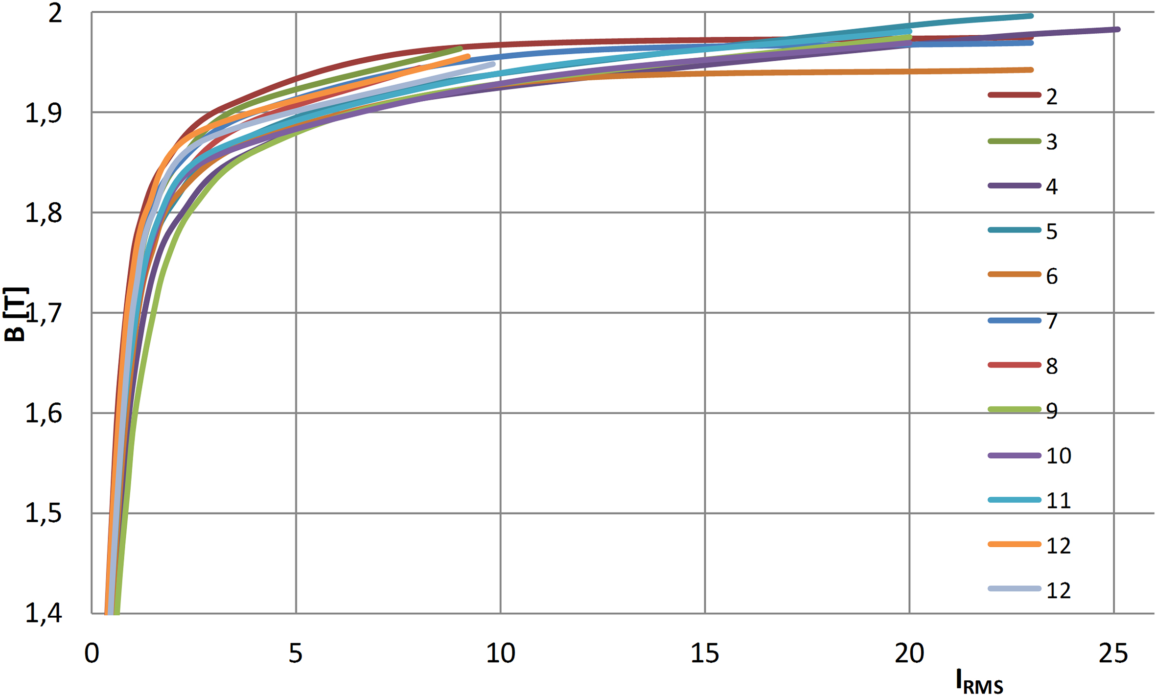
The measured magnetizing current in the circuit of Fig. 1 for different submagnetizing current (red – IDC 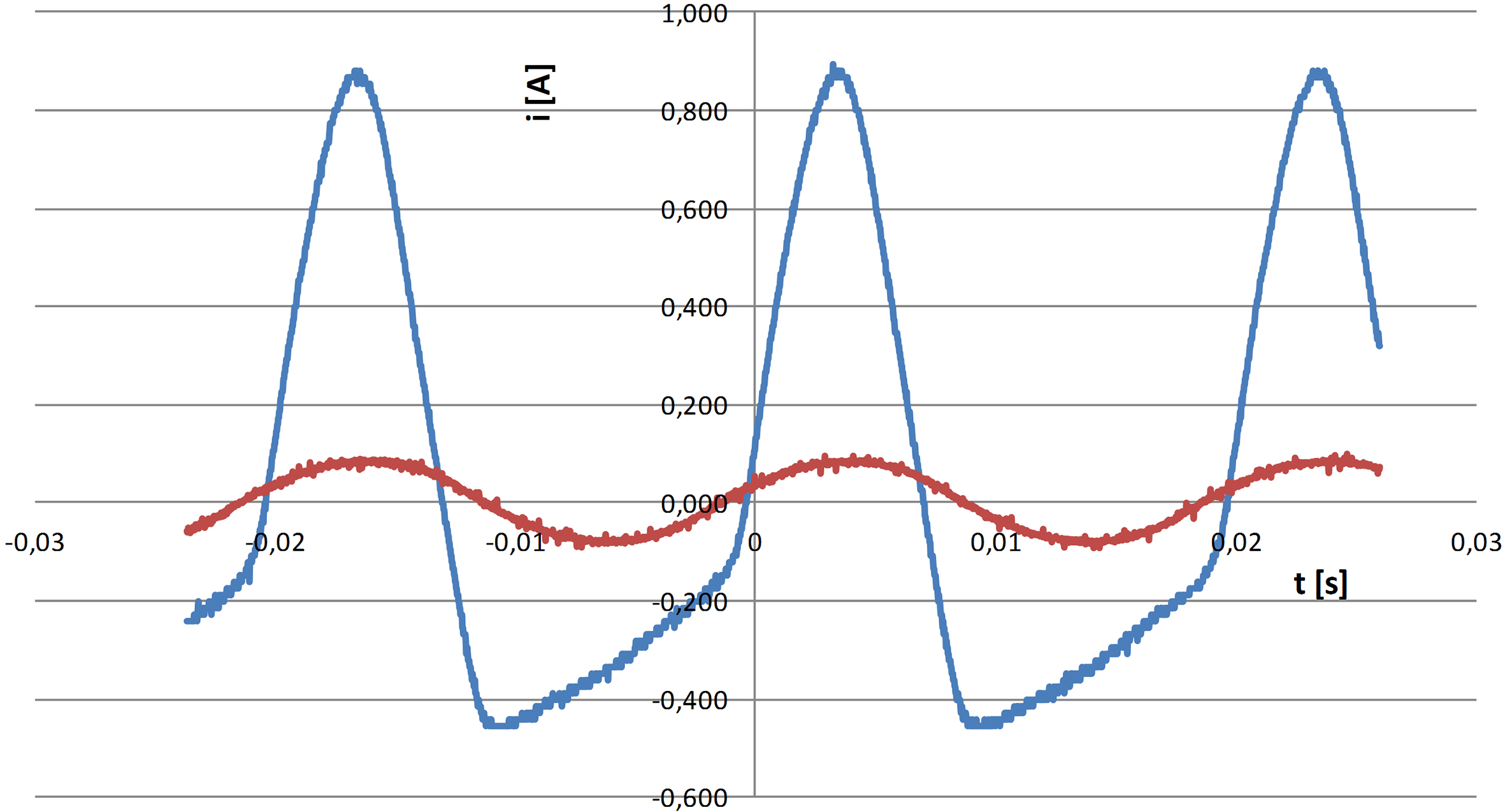
The accuracy of calculating the magnetizing current depends also on the sheet metal used for the core production. It was affirmed during the production of transformers that the value of magnetizing current differed for identical individuals. This occurs, first of all, in the case of producing the cores of transformer from various metals sheet deliverers [4]. Figure 7 shows the magnetization characteristics of eleven different sheet metals. There are significant differences in the parameters, especially for induction values above 1.4 T. This, of course, results in changes in the shape and magnitude of the magnetizing current of the transformer made of different types of sheet metal.
The magnetization characteristic adopted for calculations in this article corresponds to a typical transformer sheet used for the production of transformers.
The use of the characteristics presented in Fig. 5 for calculating the magnetizing current of any transformer requires knowledge of the number of windings of the supply winding and the length of the magnetic flux path. The number of turns of the supply winding of the transformers from figure 2 was equal to 394.
For examining the influence of submagnetizing on the magnetizing current, investigations were conducted in measuring arrangement presented on Fig. 1. The first windings, connected in parallel, are supplied with AC current and they are exciting the core. Secondary windings are supplied with DC current (changed in a wide range), submagnetising and saturating the core. Figures 8, 9 and 10 show the magnetizing currents as a function of the submagnetizing current for three different values of AC flux density (0.51, 1.03 and 1.49 T). For the presented cases, the maximum value of flux density in the core can be determined on the basis of the maximum value of the magnetizing current and the characteristic of Fig. 3.
Using the calculation method presented in the previous chapter, theoretical calculations of currents for different values of submagnetizing flux density were made and shown in Fig. 11.
The measured magnetizing current in the circuit of Fig. 1 for different submagnetizing current (red – IDC 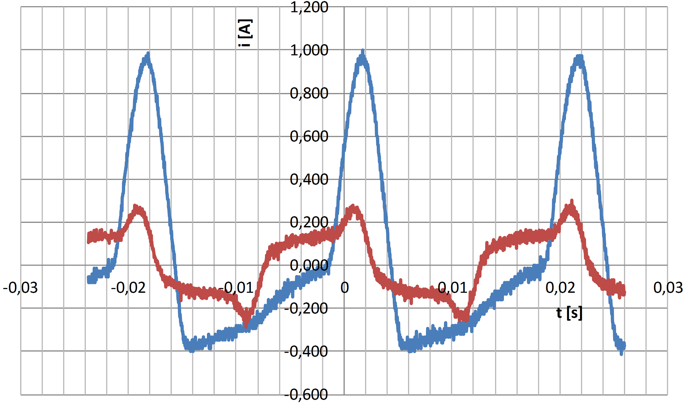
The measured magnetizing current in the circuit of Fig. 1 for different submagnetizing current (red – IDC 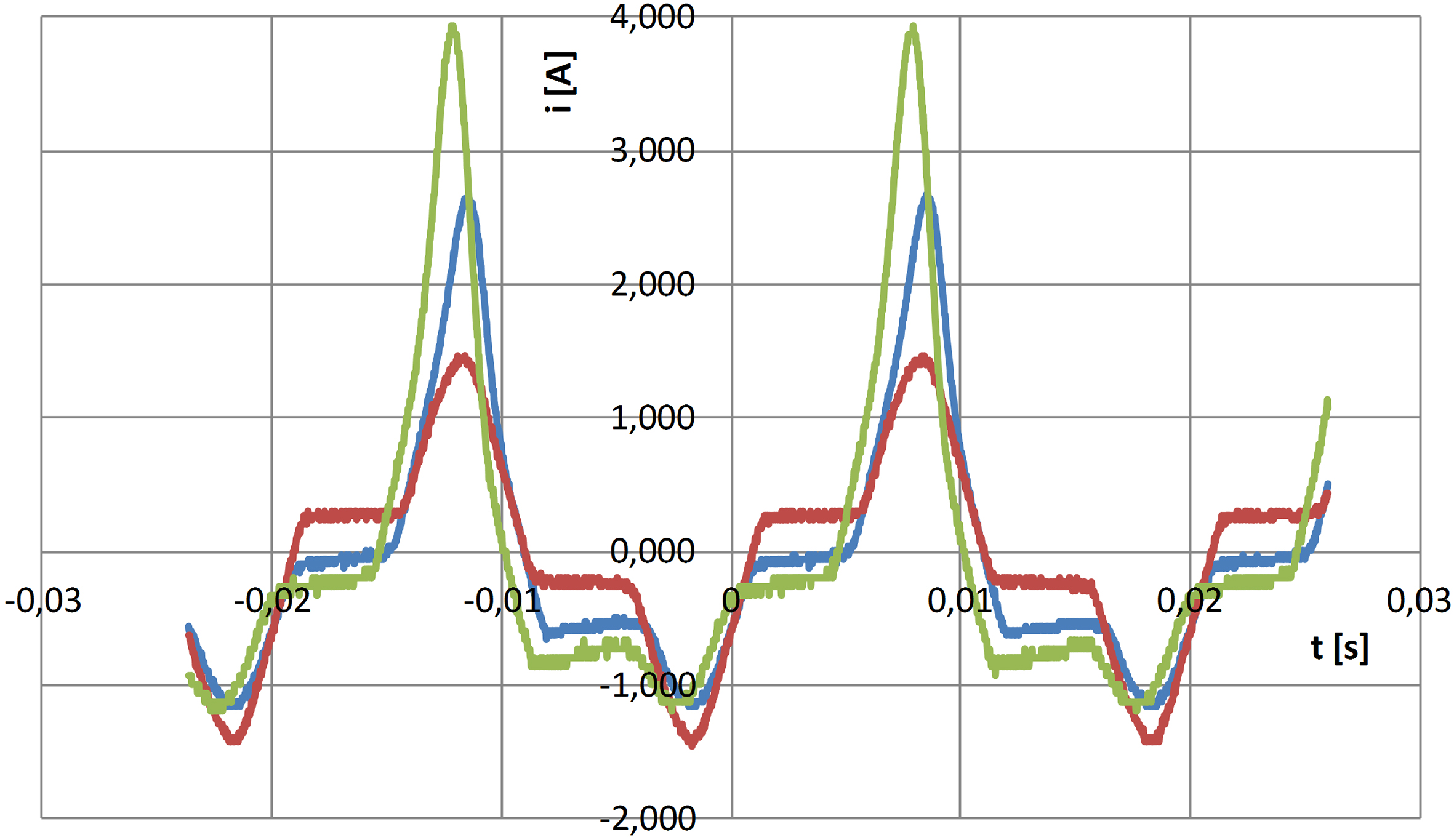
Magnetizing current calculated from the characteristics of Fig. 5 for different values of flux density and submagnetizing currents.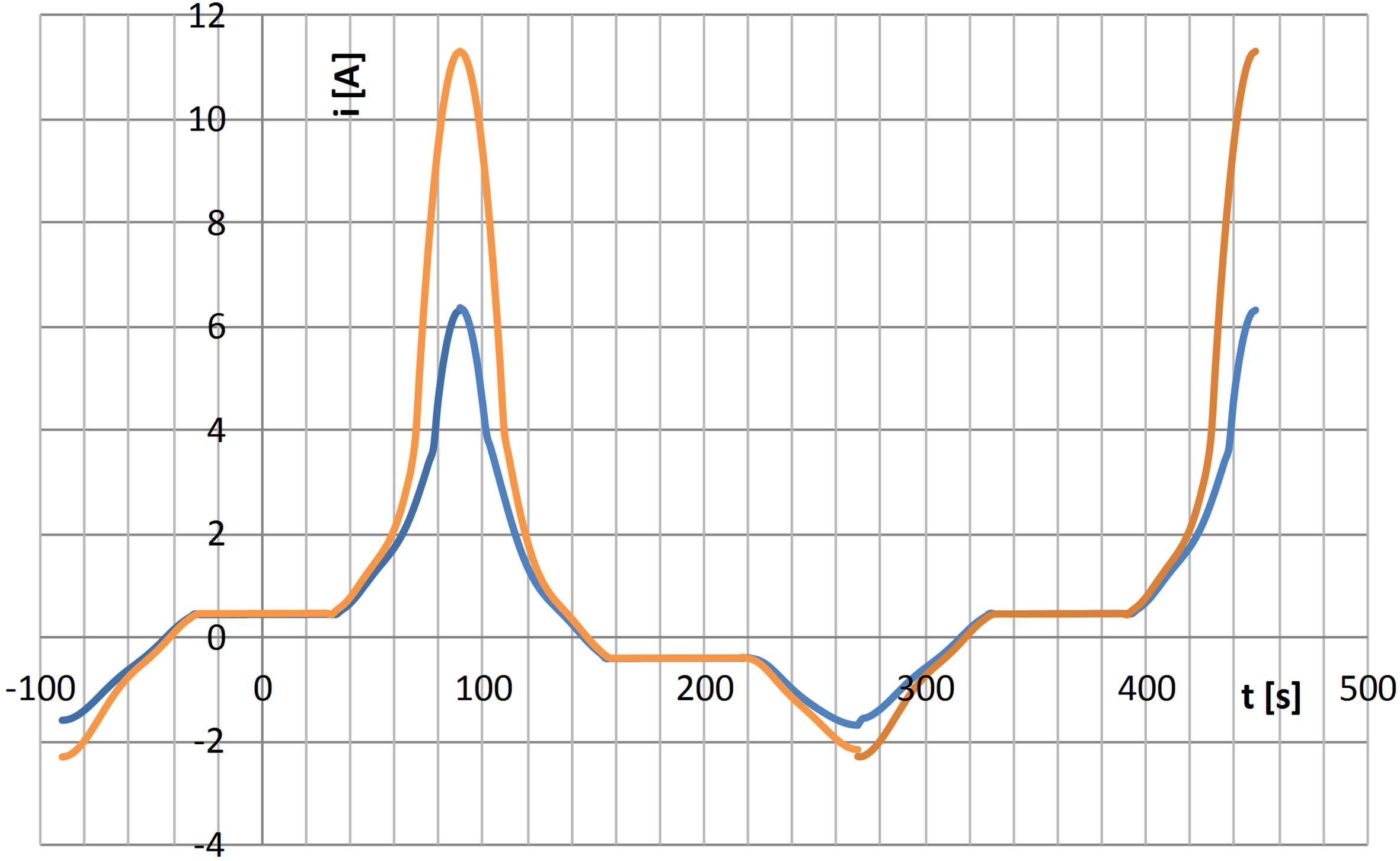
Phase magnetizing current (I1, I2, I3) of three-phase, three-leg transformer at submagnetizing of DC flux (star connection) [3].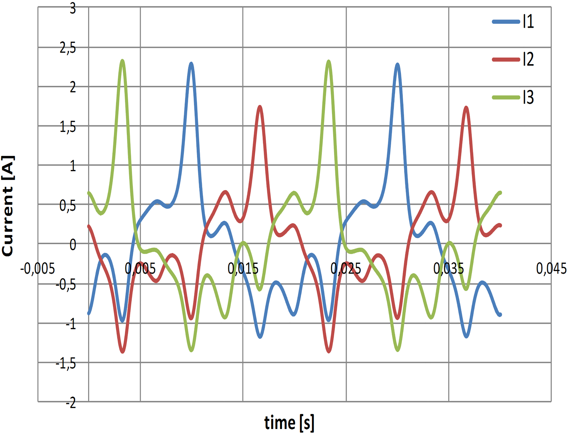
For the measuring system of Fig. 1 the DC flux is closed by a low reluctance, and already a small DC value causes a strong submagnetizing of the core.
In case of a three-phase, three-leg transformer the generated DC magnetic flux closes up through a path with high reluctance [3]. The impedance for this flux (yoke flux) can be easily determined from the measurement, connecting the secondary windings in parallel and supplying them with a single phase AC voltage. In case of the Yyn connection of a three-leg, three-phase transformer the relative value of the impedance is equal 50% to 70%. It is about 10 times higher than the short circuit impedance of the transformer [1, 2]. Therefore the value of this flux is not so high, for certain values of the DC submagnetizing current. In this case, simultaneous submagnetization of all columns occurs, causing increase amplitudes and asymmetry of each phase currents (Fig. 12) [3].
This results, for example, in converter transformers that the increase in flux density in the core does not usually exceed 10 percent.
Phase magnetizing current (I1, I2, I3) of transformer for submagnetizing of middle column.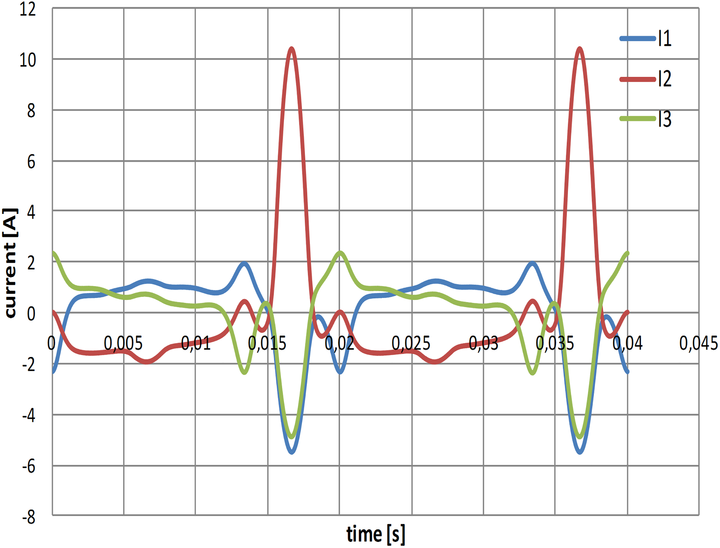
For a three phase, five-leg core transformers the DC flux is quite high even for relatively small values of DC current, because of low reluctance for this flux component (like in single phase transformers), which closes through the core return columns. A similar situation occurs when one of the three columns of a three-phase transformer is magnetized [3, 4]. In this case, the flux of the DC component flows through the other two columns of the transformer. Figure 13 shows the shape of the magnetizing current in each phase of supplying windings for submagnetizing of the middle column of three phase three-leg transformer. The increase of the magnetizing current in this case due to the strong saturation of the core is so large that it can prevent its further operation [5].
Calculation of magnetizing currents of three-phase transformers can be carried out similarly as described in Chapter 3. It should be taken here in addition into account the core construction, winding connection and the kind of submagnetization.
The operation of special transformers and chokes is often connected with submagnetizing of the core with a DC component of flux. This can cause significant saturation of individual parts of the magnetic circuit and increase the magnetizing current. This results in deterioration of magnetic and vibroacoustic parameters, ie increase in the core loss, vibration and noise emitted by the core to the environment. Calculating the magnetizing current of transformers and chokes working under such conditions at the design stage, allows the determination of the maximum of flux density in the individual parts of the magnetic circuit, which affects the change of the aforementioned parameters. This allows to design transformers that meet the standards and requirements of the customers.