
Abstract
The authors designed a rotor structure of permanent magnet synchronous machine (PMSM) to develop a large output power by the proposed topology optimization method. As the obtained magnet shape is complex and less practical, this paper proposes a rotor topology of PMSM considering ease of manufacturing. Finite element simulation confirms that the average output power of the designed machine is higher than that of a generator used in Prius under the condition of the same stator, the same weight of rotor and the same permanent magnet volume.
Introduction
Topology optimization methods allow designers to obtain an initial conceptual structure starting with minimal information on the design object, and therefore they are very promising methods [1–3]. The authors thought that the first step to reach an optimum design should be to optimize the topology of the machine by starting from an empty space, which takes into account several kinds of material. They proposed a topology optimization method considering the cluster of material and the cleaning method of the cluster in the Genetic algorithm (GA) [4], and designed a rotor structure of PMSM to develop a large output power [5]. However, the obtained magnet shapes are complex and less practical, a smoothing technique is necessary in order to design the final shape considering ease of manufacturing.
This paper proposes a rotor topology of PMSM considering ease of manufacturing, and then compares its performance with that of a generator used in Prius.
Design by proposed topology optimization method
Here, we explain the topology optimization method, we have proposed [4]. Figure 1 shows the PMS generator used in Prius, which has eight poles. We design the rotor topology of one pole region, and it is split into finite element meshes for the 2-D finite element method. The proposed method is composed of the GA combined with the concept of cluster and the cleaning procedure. The material of several elements-e.g., a cell-is associated with a gene in the chromosome. For example, if we consider five types of materials-e.g., air, iron, and magnet magnetized in r-direction, x-direction and 45 degree-direction, which are set to 0 through 4, respectively. In the GA, individuals are growing up by “crossover” and “mutation”. Two parents are selected randomly and some genes are selected to be exchanged by a uniform crossover with a crossover ratio, and then two new children are generated. The children inherit the good characteristics of parents by repeating the process. In addition, the elitist selection is adopted so as to inherit an individual, which has the maximum fitness function, to the next generation.

Rotor used in Prius generator.
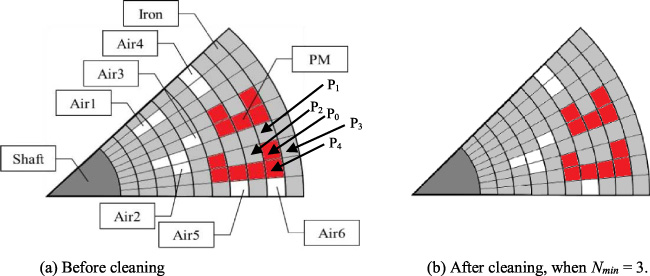
An example of the cleaning method.
We proposed the concept of the cluster, that is, the cell with same types of material. For example, the cluster is explained using Fig 2(a). Air 1 is a cluster and the number of cells is two. Air 2 and 3 are regarded as one cluster, and the number of cells is four. Air 4 and 5 are regarded as one cluster because they are connected by the periodic boundary. If the cluster is small, that is, the number of cells in the region is smaller than an integer N min , the cleaning procedure is carried out. Then, the small cell is changed to the surrounding material. This cleaning procedure for a small cluster of materials can remove the floating pieces of the material. For example, if N min = 3, Air 1 and 6 are changed to the surrounding material iron because the number of cells is less than N min . Air 2 and 3 remain as they are, because Air 2 and 3 are connecting each other and the number of cells is not less than N min . Air 4 and 5 also remain because they are connecting through the periodic boundary and the number of cells is not less than N min as shown in Fig. 2.
Figure 3 shows the flowchart of the proposed method, where the thick frame parts are our original and are different from the conventional GA. At the first iteration we designed the distribution of material in 90 cells in order to obtain a rough topology, which is composed of 10 by 9 parts as shown in Fig. 2. And at the second iteration the distribution of material in 810 cells, which is composed of 30 by 27 parts were designed in order to obtain a fine topology. Therefore, the computational cost can be reduced than the method using a large number of design variables at the first iteration. The ratios of crossover and mutation are set to 20% and 2%, respectively. The number of generations is set to 300 at the first iteration and 600 at the second iteration, that is, the total number of generations is 900. At the second iteration, a set of initial individuals is generated by using the individual that has the best fitness at the first iteration. The initial material at the second iteration in cell P0 is generated by the probability of 1/5 from the material in cells P0, P1, P2, P3, and P4. In order to design the rotor with a high electric power while reducing the volume of PMs, the following fitness function is used.
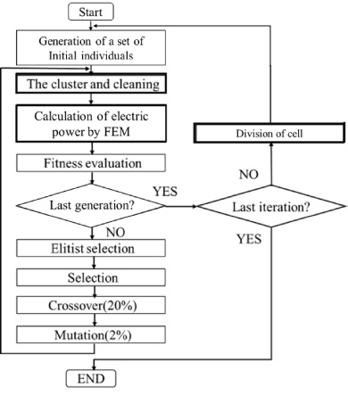
Flowchart of the proposed method.
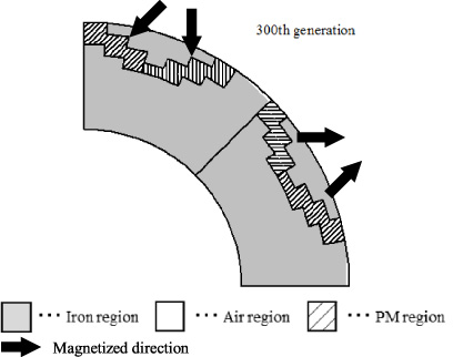
Obtained design result where N min = 4 at the first iteration.
Figure 4 shows the obtained result at the first iteration when N min = 4. It appears as a V -shaped interior PM machine. However, the shape of PM is not smooth. Figure 5 shows the obtained results at the second iteration for different N min , where one pole-pair region is shown for easy understanding by drawing the magnetization direction. Figure 5(c) shows the rotor when N min = 4 at the first iteration and 28 at the second iteration. As the shape of PM shown in Fig. 5(c) is much smoother than that in Fig. 4, this paper sets the number of iterations to two. This rotor is very similar to that of Prius generator. However, the position of PM in the pole moves also in the direction of rotation. Figure 5(d) shows the rotor when N min = 5 at the first iteration and 37 at the second iteration. The obtained rotor appears as a type of surface PM machine with one PM in one pole. The position of PM in the pole moves a little bit to CCW, that is, in the direction of rotation. Figure 5(a) shows the obtained rotor shape when N min = 1, that is, without using the cleaning procedure, which has a lot of small pieces of magnet remains. Figure 5(b) shows the obtained rotor, which has the highest fitness function as shown in Table 1. It is noted that the obtained shape is asymmetrical. As the rotor topology shown in Fig. 5(b) has the highest fitness function, this paper chooses this shape in the next chapter.
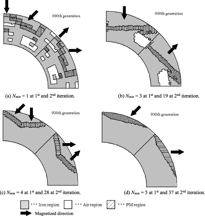
Obtained design results.
Fitness function, the volume of PM and the average outpour power for each design result
Proposal of rotor structure
It is found that the designed rotor shape shown in Fig. 5(b) is complex and less practical. In order to take into consideration ease of manufacturing, this paper assumes the obtained rotor structure to be represented by a hexahedron permanent magnet and air region per pole as shown in Fig. 6. Here,
The volume of permanent magnets is the same as that of Prius generator, and PMs are magnetized in the vertical direction. The volume of air region is the same as that of Prius generator. Core region is introduced near the outer surface of the rotor to make the machine strong to centrifugal forces. The width of introduced core region is the same as that of Prius generator. Air region of triangular prism is introduced between PM and the surface of rotor in order to reduce magnetic flux flowing through the core region described in (3). Stator is absolutely the same as that in Prius generator. Although rotor of model 1 has iron cores separated to two parts, rotor of model 2 has an integrated core to make the machine strong.
Figure 7 shows one fourth region of each generator with proposed rotor structure considering ease of manufacturing. This paper calculates their performance by using 3-D FEM analysis.

Proposed rotor structure considering ease of manufacturing.

Proposed rotor structure considering ease of manufacturing for 3D FEM analysis.
Figure 8 shows the waveforms of electromotive force, when rotating at 13,500 rpm, and Table 2 shows the comparison of performances. It is found that the waveforms of EMF produced by model 1 and 2 are approximately the same as that of Prius generator. The effective value of EMF produced by model 2 are improved by 7.2% than the Prius generator.

Comparison of electromotive forces at no-load.

Comparison of output powers at a stator current of 80 A.
Comparison of performances
Figure 9 shows the waveform of output power when the stator current of 80 A is input. The phase angle is chosen so as to produce the maximum output power. It is found that the waveforms produced by model 1 and 2 are approximately the same as that of Prius model. They include the ripple component of sixth order of fundamental frequency. Table 2 shows that the average value of output power of model 2 is improved by 7.2% than the Prius generator, and that the ripple of output power of model 2 is fortunately reduced to 61%.
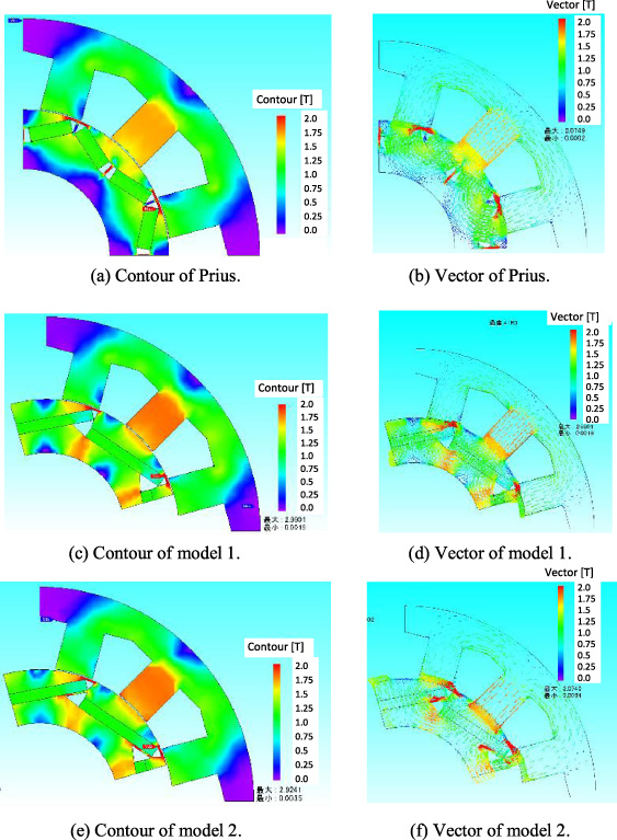
Comparison of magnetic flux distribution at no-load.
Here, we discuss the improvement of the average output power. This improvement is due to the improvement of electromotive force. Figure 10 shows the magnetic flux distributions at no-load for three models. The rotor position is chosen so that the flux linkage of U-phase is maximum. Note that the maximum flux linkage means the integral of electromotive force with respect to half positive region. One pole region of Prius rotor is composed of two PMs, and the other models are composed of only one PM. Contour of Prius model shows that some magnetic flux flows through between two PMs, therefore this flux is not effective. This leakage flux makes the reduction of flux linkage, and thus the reduction of electromotive force. As a result, the output powers of model 1 and 2 become higher than that of Prius generator.
This paper has designed a novel rotor topology for the Prius generator by using the topology optimization method the authors proposed, and then proposed two kinds of rotor considering ease of manufacturing. It is noted that this rotor structure cannot be obtained by the usual shape optimization methods, but it is obtained by the proposed topology method. It is clarified by 3-D FE analysis that the average output power of the designed machine is higher than that of Prius machine under the condition of the same stator, the same weight of rotor and the same permanent magnet volume.