
Abstract
In this paper, power losses in high-speed switched reluctance machine (HS-SRM) is studied considering the copper loss, including skin and proximity effect, iron loss in machine side; switching and conduction losses in the drive circuit side using interactive coupled simulation methods. In high frequency fed electric machines, copper losses are increased due to the skin and proximity effects. Moreover, iron losses play a significant role in total electrical losses. Nevertheless, its computation is not straight. In addition, power electronics switching devices cause both conduction and switching losses in the SRM drive circuit. Switching loss may reach excessive levels with the high-frequency switching. In this study, the losses are calculated detailed though coupled simulation method. Different wire constructions in the bundle are analyzed and compared. Finally, circuit simulation is performed on different switching devices. The results prove that high-speed switched reluctance machine driving and operating efficiency is really sensible to design methodology with suitable material and device selection.
Keywords
Introduction
The finite element method (FEM) has been employed broadly for electric machine design and analysis in coupled decades. Nowadays, several simulation platforms can be integrated with each other and work together simultaneously with advancing and pervasive computing technology. High-speed central processing units (CPUs) with a combination of parallel processing feature and high capability FEM software and simulation platforms provide accurate and timely effective studies.
In conventional low-speed electric machines, skin and proximity effects are usually ignored in machine analysis. However, very fast rate of change of flux with respect to the time in high-speed electric machines causes a disturbance in the current density of the wire which is in a non-ignorable level [1]. Thus, skin and proximity effect should be considered in coil resistance calculation and machine performance analyses.
Iron losses constitute the major part of the electrical losses in high-speed, high frequency fed electric machines. Unluckily, it’s an accurate calculation in the design stage is not straightforward. A lot of research was handled in the literature for modeling the iron losses [2, 3, 4, 5, 6, 7, 8, 9, 10]. These studies can be classified into three major sections. Steinmetz equations were firstly presented by Steinmetz in 1892 [11]. However, the study assumes that flux density in the electric machine is purely sinusoidal which could give some approximate values for sinusoidal fed electric machines. However, for switched reluctance machines, it is not acceptable as the current waveform contains low-to-high order harmonics. The Steinmetz equation was modified and developed by several researchers to take into account the non-sinusoidal fed electric machine iron loss calculations. Secondly, iron loss separation method is presented by dividing the losses into separate forms as hysteresis, core and excess losses [12]. Although the method is not accepted by the physicists as the separation does not have any meaning in terms of physics, the method is quite common in engineering iron loss calculations [8]. Thirdly, the iron loss mathematical model is presented based on exact measurement of the material loss characteristics [13]. Despite all these mathematical and empirical approaches, there are still uncertainties/problems about the iron loss prediction.
In high-speed electric machines, the other important loss part emerges in the driving circuit with semiconductor switching losses because of the high-frequency switching. These losses cause Joule heating in the power devices. To remove the heat from the semiconductors, different coolants such as heat sinks, air forced or liquid coolants are used. If the heat reaches excessive levels, the used coolants do not have enough time to remove the heat from the junction which leads to burning out the semiconductor. Hence, limiting the switching power losses in a safe range is one of the critical issues in high-speed electric machine applications.
In this study, the mentioned three critical issues which are skin and proximity effect, iron loss and switching loss are analyzed, detailed for high speed switched reluctance machine applications. The coupled simulation method is proposed for calculating these losses. In Section 2, coupled simulation is defined and the establishment of the integrated simulation model is mentioned. In part III, loss analyses are sequentially executed and their answers are explicated. Finally, the results are summarized in the conclusion section.
Coupled simulation
Coupled simulation is an integration of two or more simulation tools on the same platform by building up the communication link between them. The goal is to perform multidisciplinary analysis and to find more realistic results with including all system components [13]. Electric machines contain mechanical, acoustic and thermodynamic phenomena. Moreover, it is driven by a power electronics circuit which requires another system modeling. Coupled simulation platform provides several advantages. Firstly, internal parameters such as power losses, flux densities, inductances can be supervised by the designer or user during electric machine simulation. Dynamic power losses such as iron losses or copper loss can be obtained in a time domain. However, it is well known that estimating the iron losses is not straightforward in conventional methods. Especially for high-frequency applications, such as high-speed electric machines, the majority of the power losses comes out in the laminated sheets with a form of iron loss. Secondly, power electronics circuit to drive the SRM will also have high-frequency switching that can generate excessive switching losses on the switches which need to be monitored carefully. With a coupled simulation, the power switches and the circuit can be modeled detailed and the losses can be monitored. Figure 1 shows the schematic diagram of the coupled simulation model. Here, the developed SRM finite element (FE) model is linked with the power electronics drive circuit which is modeled in Simplorer. The switching signals are generated by the developed SRM control algorithm in Matlab-Simulink. The algorithm flowchart can be seen in Fig. 2. The SRM is controlled with hysteresis mode current control. If the phase current exceeds the specified set upper band value, hysteresis block output generates zero, which turns-off the power switches. When the phase current falls below the lower band value, the block generates one which means that the power switches will be turned-on as shown in Fig. 3 [14, 15, 16]. The phase windings are magnetically decoupled in SRM. So, each phase is controlled separately. As mentioned above, coupled simulation is essential for high-speed SRM analysis because of the high frequency in both machine side and driver side.
Schematic diagram of the coupled simulation model.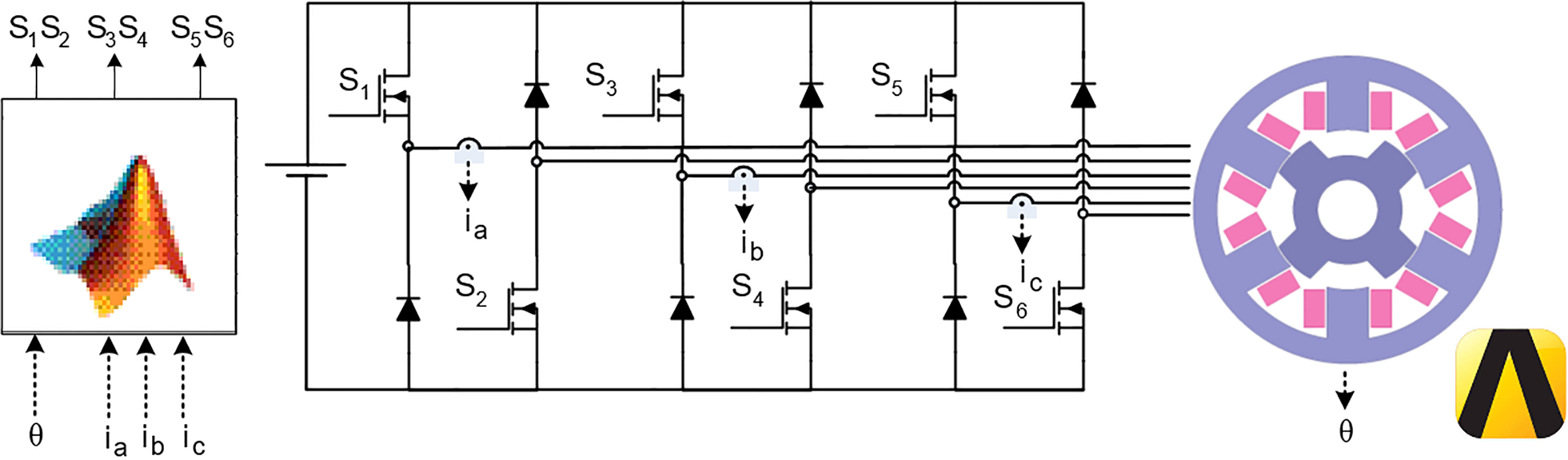
The control flowchart of switched reluctance machine.
Hysteresis current control in SRMs and related switching signal waveform.
In this section, three electrical loss parameters will be analyzed for high-speed SRM application.
Skin and proximity effect
Skin or penetration depth is determined by the depth of electromagnetic field wave penetration into the specified medium [17]. A used wire in the stator slots is assumed to be a good electrical conductor. So,
From the given equations above it is clear that
Skin depth representation.
where
Equation (1) can be rewritten as,
Equation (6) shows that electric field which is traveling through the conductor is exponentially damping with
Skin effect causes the resistance increment in wires. DC resistance can be calculated as,
where
Fast fourier transform of hysteresis mode current at 15 krpm rotational speed.
Here,
Fast fourier transform of single pulse mode current at 50 krpm rotational speed.
Fast fourier transform of single pulse mode current at 100 krpm rotational speed.
The typical current waveform of SRM contains several order harmonic frequencies in addition to the fundamental excitation frequency as given in Fig. 3. So, the conductor will have different skin depth and the resistance value for each harmonic component. Typical hysteresis and single pulse mode current waveforms and their harmonic contents at different rotational speeds are given in Figs 5–7, respectively. As expected, all current waveforms have several harmonic contents. However, considerable current magnitudes show up till 60 kHz at 100 krpm speed. The skin effect analysis results which are performed in finite element analysis (FEA) method are provided in Fig. 8. The figures clearly indicate that current densities are more concentrated on the conductor surface rather than the center. Moreover, this concentration increases with the frequency, as expected. At 5 kHz, the average current density is around 8 A/mm
Skin effect analysis of the conductor at different frequencies.
Photo of the Litz wire.
Skin effect analysis on the Litz wire at different frequencies.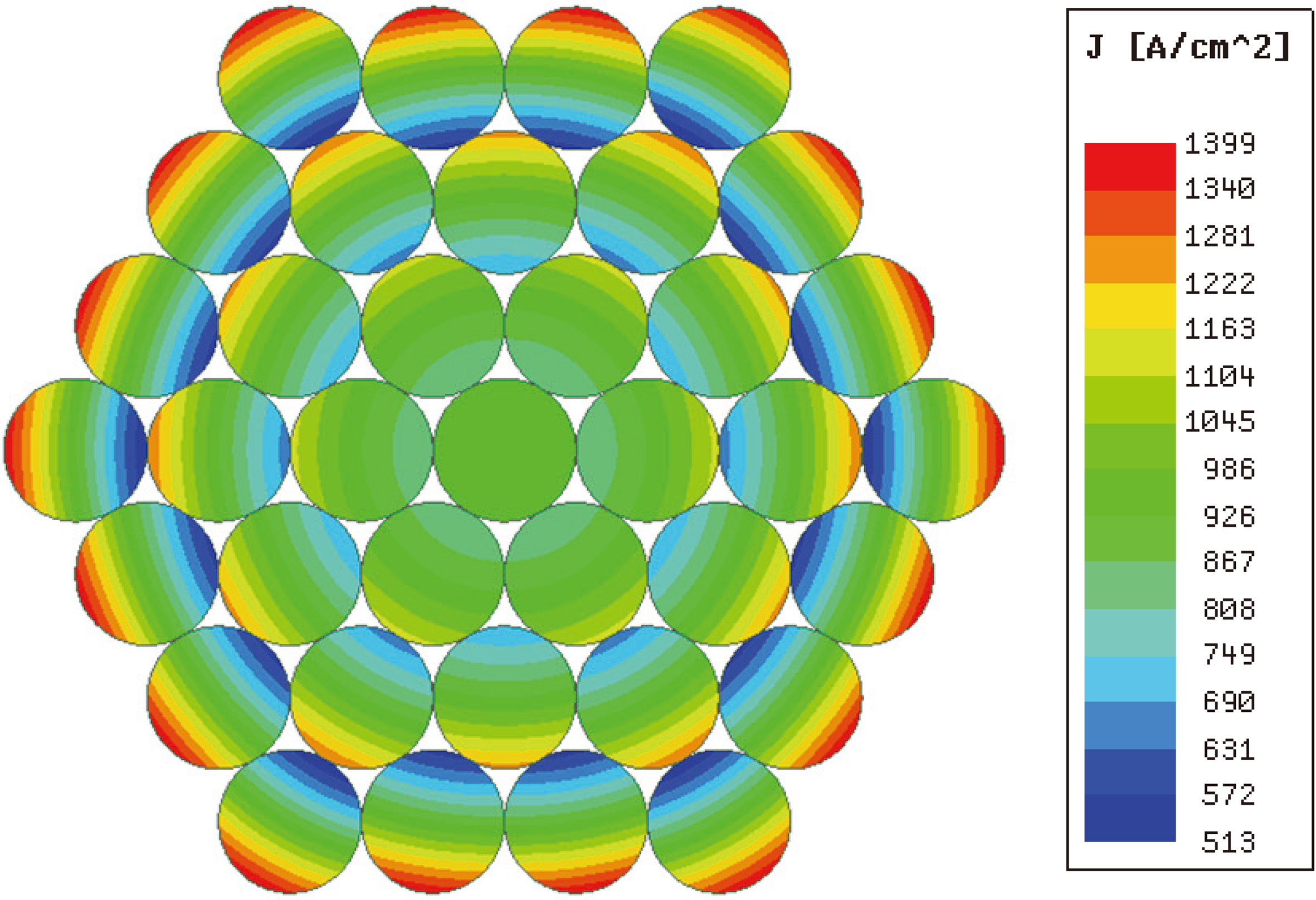
Static flux linkage curves of developed SRM.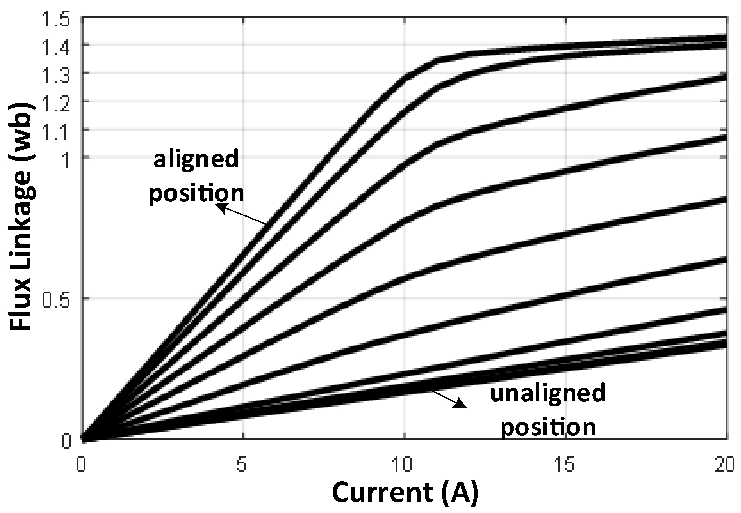
SRM angle optimization results for 20 A driving current
SRM control parameters optimization flowchart.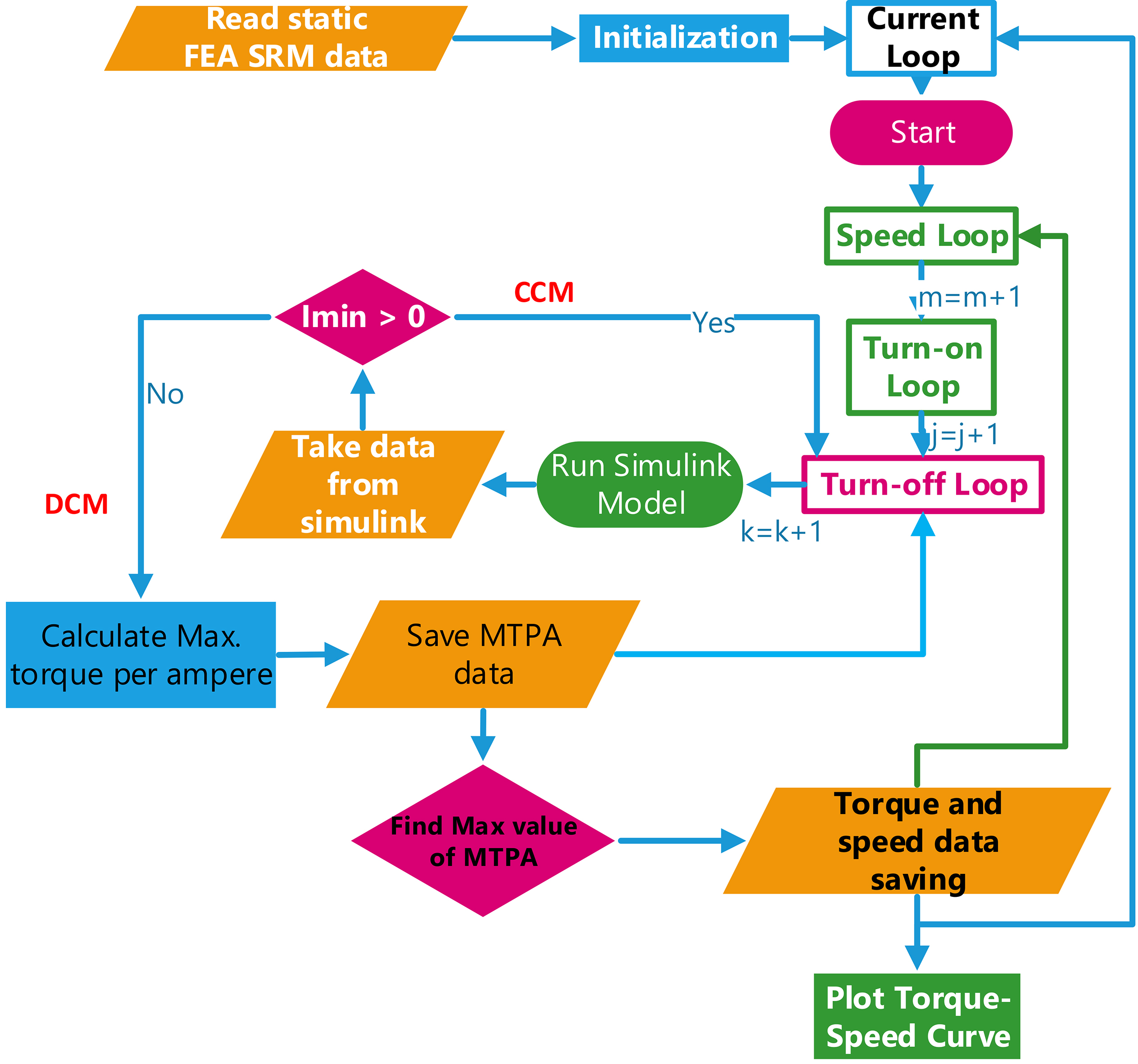
SRM dynamic simulation results with one phase excitation at 5 krpm.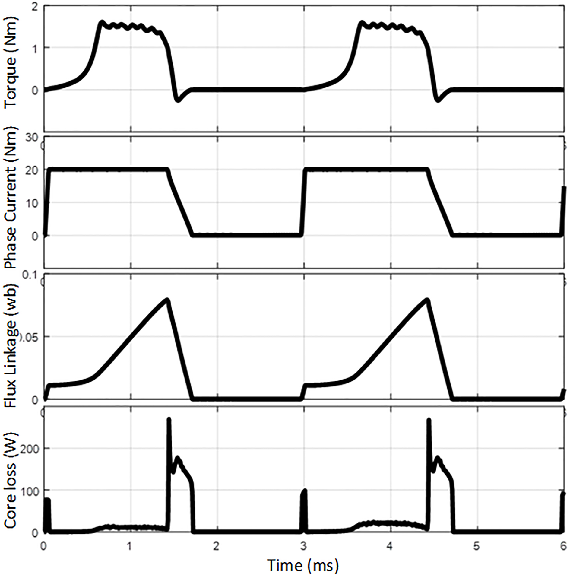
SRM dynamic simulation results with one phase excitation at 50 krpm.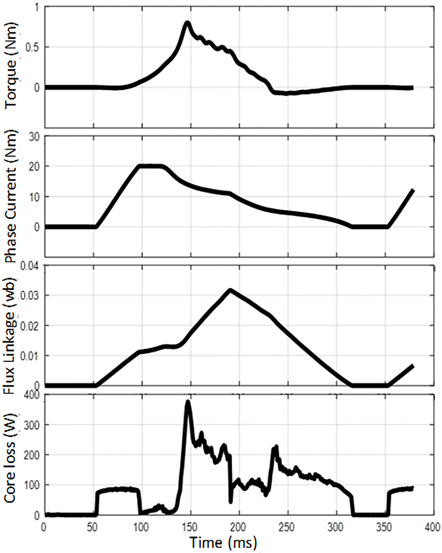
Core loss data at different frequencies and average core loss of the SRM for different speeds and current levels.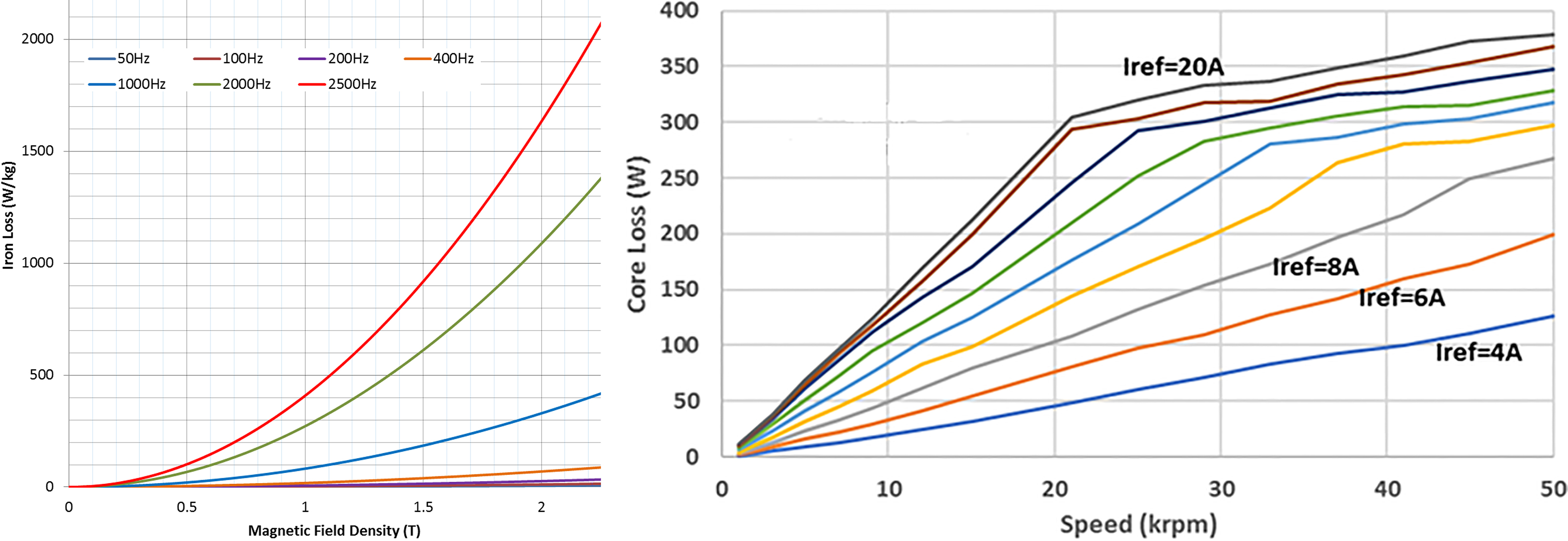
(a) The efficiency (%), (b) core loss (W) and (c) copper loss (W) of the developed SRM with respect to speed and torque.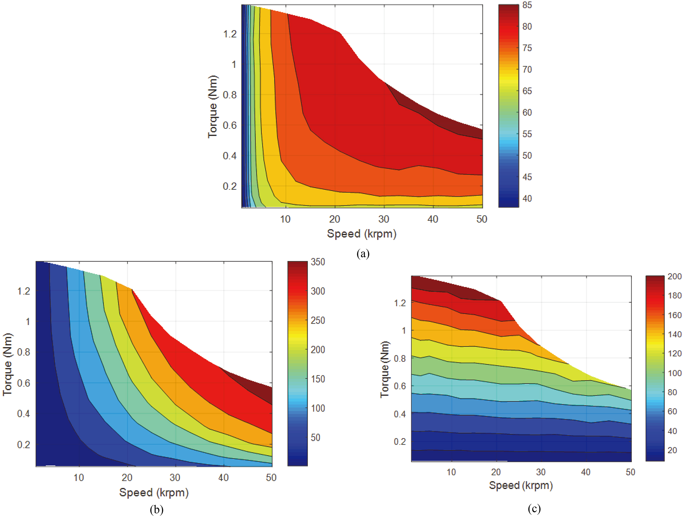
Litz wire is simulated for a bundle of 37 conductors in a wire. The FEA simulation result is shown in Fig. 10. The result clearly proves the effectiveness of the Litz wire for uniformly current sharing where the difference between the maximum and minimum current densities are reduced. However, there are some current sharing differences between the conductors at this time. As the current flowing in each conductor produces its self-magnetic field, the interaction of the magnetic fields affects the neighbor conductors, is called proximity effect. Proximity effect either may compromise in the bundle of the Litz wire or may show up with the interaction of the wires in the slot of the stator.
In high-speed electric machine applications, iron losses usually form a major part of the electrical losses. Core losses can be classified into hysteresis loss, eddy current loss and excess loss where the generalized core loss formula is given in Eqs (9) and (10). Here,
As mentioned in the introduction section, core loss calculations are not straightforward. Especially at high speeds, the results are often far away from the experimented results. In this study, coupled simulation method is proposed for iron loss calculation. The simulation platform is provided in Fig. 1. The control algorithm of the high-speed SRM is developed in Matlab-Simulink. Finite element model of the SRM is established in Ansys-Maxwell. Both models are interconnected with the power driving circuit which includes a detailed semiconductor model in Ansys-Simplorer.
First of all, turn-on, turn-off angles and the reference current parameters should be determined for each operating point with the following optimization algorithm which is executed post-processed with the static obtained flux linkage and torque data from FEA. The static flux linkage curves are provided in Fig. 11. The online FEA method is not preferred for the control parameter optimization as it would take considerable time. The control parameter optimization algorithm flow chart is given in Fig. 12. Three successive loops are executed for deciding optimal reference current, turn-on, and turn-off angles. For the efficient drive, maximum torque per ampere (MTPA) method is usually preferred. After executing the code, the optimal values are put on the table as shown in Table 1. The required data are ready for iron loss and efficiency analysis which will be performed through FEA coupled simulation.
For coupled simulation, reference current waveforms are determined with optimized angles as given in Fig. 12. Figures 13 and 14 show the one phase excited dynamic coupled simulation results at low and high operating speeds i.e. 5 krpm and 50 krpm, respectively. At 5 krpm, developed SRM is under the hysteresis control area where the current is regulated at desired level over a conduction. However, at 50 krpm, the back-EMF of the SRM reaches to the DC-Bus supply voltage level so the phase current cannot be regulated in all conduction time. From the Fig. 14, it can be understood that the phase current is partly regulated in a short time then it goes to the single switching area. The results show that the core loss comes up suddenly during turning on and turning off at low speeds. This can be explained by magnetizing and demagnetizing issues. Magnetic materials have magnetic domains and their positions are arbitrary distributed in their structure. When the current is applied to the phase, the domains in the lamination material are subjected to the magnetic field which makes the domain positions parallel to the applied field. If the magnetic field changes its position the magnetic domains positions will tend to move together with the magnetic source. If the magnetic field is totally removed, the magnetic domains go back to their arbitrary positions. To sum up, these movements generate particularly kinetic energy and causes a heat rise in the material. This loss type is named as hysteresis loss. At low speed, as the excitation frequency is relatively low, the hysteresis loss effect can be easily seen in the case of turning-on and turning-off. It should be noted here that turning off case generates more core loss than the turning-on. The reason is the potential voltage difference between the back-EMF and DC-bus voltage. As the applied voltage is -VDC on the turning-off case, the potential voltage is high, and the magnetic stored energy suddenly flows to the DC bus. Hence the flux linkage rapidly goes to the zero which causes relatively high core loss. Figure 14 shows the 50 krpm dynamic coupled simulation results. As expected, core loss increases with the rotational speed (or the excitation frequency).
The total iron loss calculation is performed at different operating speeds and current levels considering all phases using coupled FEA method. Figure 15 shows the core loss data of used electrical steel at different operating frequencies and average core loss in the SRM with respect to the current level and speed. The meaningful result is obtained that the core loss rising slope decreases when the machine starts to get into the single pulse current mode. In conclusion, single pulse mode has better core loss behavior than current chopping mode. However, the single pulse mode causes higher torque ripple than chopping mode. So there is a tradeoff between the core loss and torque ripple. Figure 16 shows the efficiency contours as a function of speed and torque. The positive effect of the single pulse mode on the efficiency can be found out at high speeds and high torque levels. In low speeds, copper loss is the major part of the electrical loss. However, at high speeds, core losses become dominant.
Switched reluctance machine offers some advantages along with potentially low cost [1]. Moreover, the phases are electrically and magnetically decoupled, SRMs can be highly reliable and safe operating. As there is no magnet or any coil in the rotor, they can be operated at very high speed. The machine drawback is coming up with the difficulty on the control side. The drive circuit topologies and control methods differ from the other candidate electric machine types such as induction machine, permanent magnet synchronous machine, DC machine etc. Figure 1 shows the most preferred circuit topology which is named with “Asymmetric Half-Bridge Converter (AHB)”. In the AHB converter, there are switching and conduction losses in the semiconductors. For high rotational speed electric machine applications, conduction loss is usually suppressed by the switching losses.
Table 2 shows the design specifications of the developed SRM where the fundamental excitation frequency at 50 krpm base speed is 3.3 kHz. To make a healthy current regulation, the switching frequency limit should be kept in around 100 kHz. For high frequency switching at small and medium power applications, MOSFET semiconductor family is usually preferred.
Design specifications of developed SRM
Design specifications of developed SRM
Switching loss in drive circuit is a challenging step in terms of modeling. Conduction loss and switching loss in one power switch can be calculated as [19],
Some MOSFET loss analysis results
Here,
However, switching losses are directly proportional to the switching frequency with a given Eq. (13) [20]. Semiconductor selection process has a crucial effect on drive efficiency. Table 3 shows some MOSFET loss analyses results which are performed based on given Eqs (11)–(13) with assuming 20 A constant drain current. The results indicate that total power loss in one switch may change in a range of 13 to 115 W depending on the selected switch. As the power loss not only affects the efficiency but also causes a heat rise in the power circuit, the designer should consider both total power loss and junction-to-case thermal resistance of the switch. Typical cooling assembly and equivalent thermal circuit diagram are shown in Fig. 17. The smaller junction-to-case thermal resistance helps to cool of the junction more than higher resistance. Hence, paying attention to the thermal resistance during the semiconductor selection process is needed. From Table 3, two power switches are the possible candidates for high-speed SRM drive circuit as highlighted with blue color. IXTH62N65X2 MOSFET is selected as its loss behavior is the best in low and high rotational speed. Couple points should be noted here that gate drive resistance affects the switching loss characteristics of the MOSFETs. To make a fair comparison, the drive resistances are determined by multiplying the test resistances with a double which is practically applicable. The test resistance values are given in the datasheet to determine the best switching time delays. The other important argument: as the phase current is usually cannot be regulated at high speeds because of the high back-EMF, MOSFETs are switching only in couple times. However, HS-SRMs inductances are relatively smaller than conventional electric machines which causes high number of switching at small speeds. Hence, MOSFET switching losses are less at 50 krpm than 5 krpm. This case clearly shows the advantage of the single pulse mode, again.
Typical semiconductor mounting on the heatsink and thermal equivalent circuit.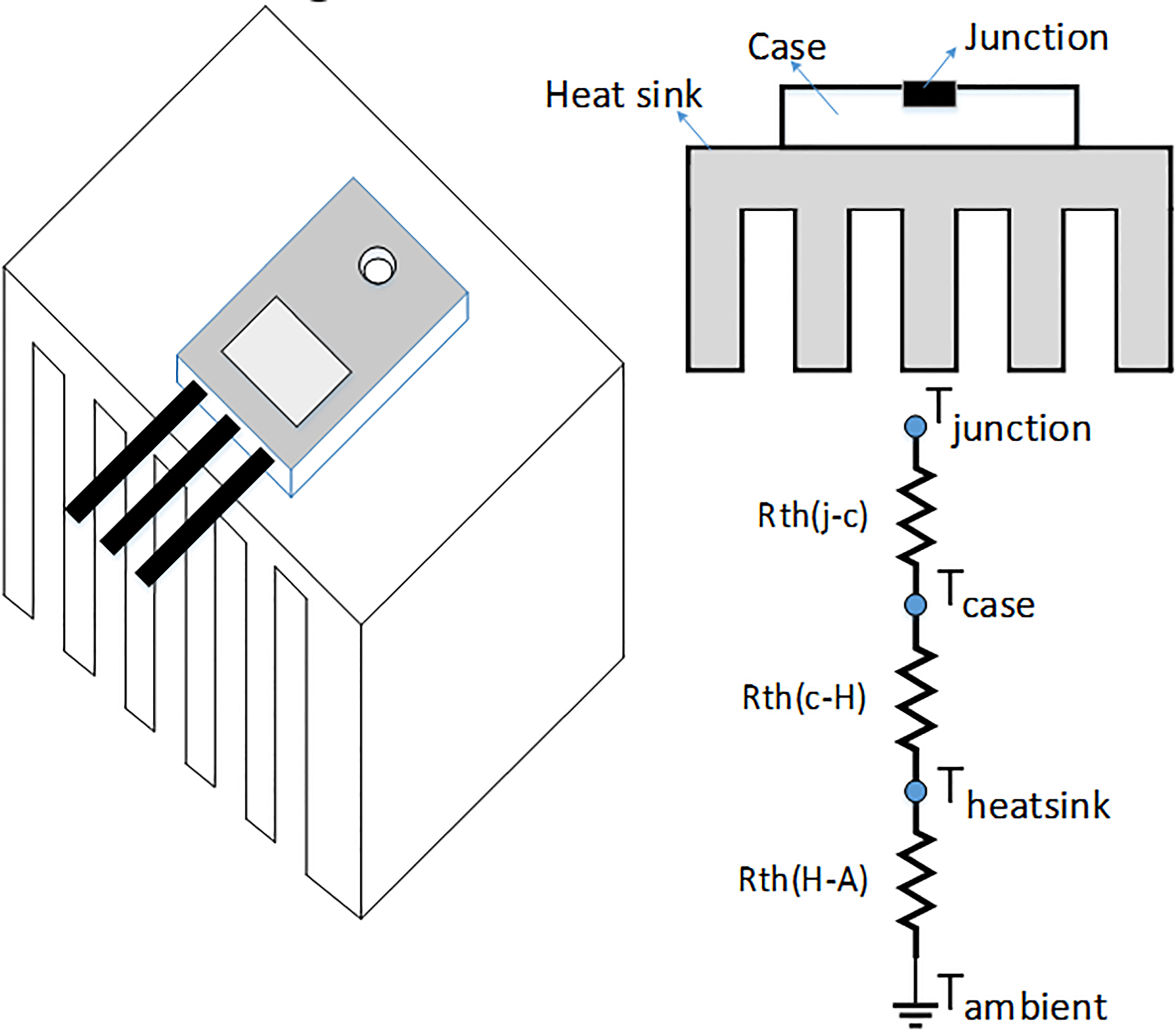
Same optimization procedure is applied to the power diode, as well [20]. To avoid unnecessary detail, related diode power loss equations are not given here. Finally, DSEP60-06A diode is selected which is shown in Table 4. Based on chosen power MOSFET and diode, power loss calculations are performed for SRMs different operating conditions. The results are shared in Fig. 19 where the results show total switching and conduction losses for AHB which have 6 power MOSFETs and 6 power diodes. As expected, the highest MOSFET switching losses are faced at lower speeds because of the high number of switching. Moreover, Fig. 19b shows that conduction losses emerge on high phase currents with I
Some diode loss analysis results
The current waveforms of the MOSFET, Diode and the phase at (a) 5 krpm and (b) 50 krpm rotational speed.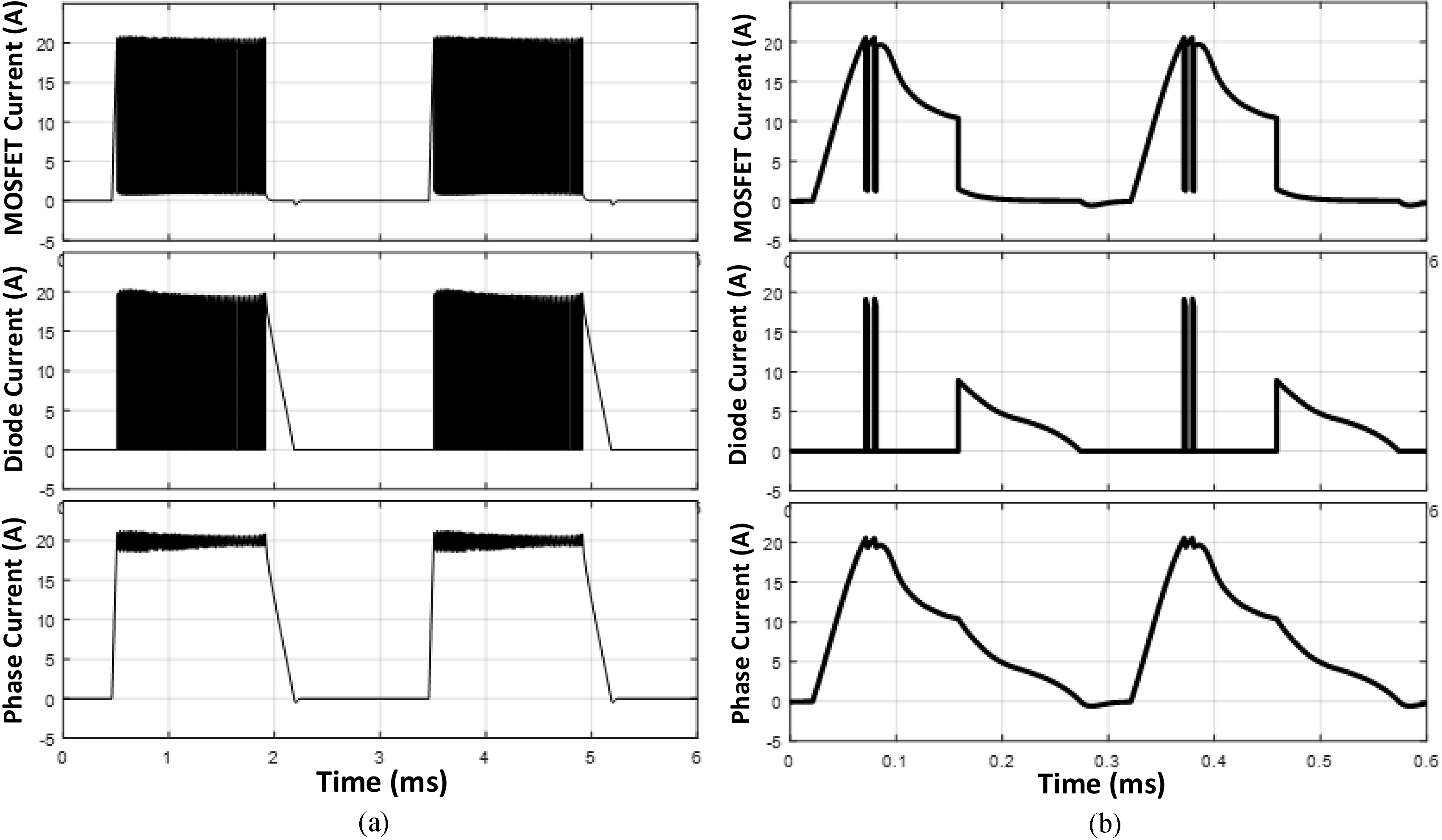
Total (a) MOSFET switching losses (W), (b) MOSFET conduction losses (W) and (c) Diode power losses (W) under different SRM operating conditions.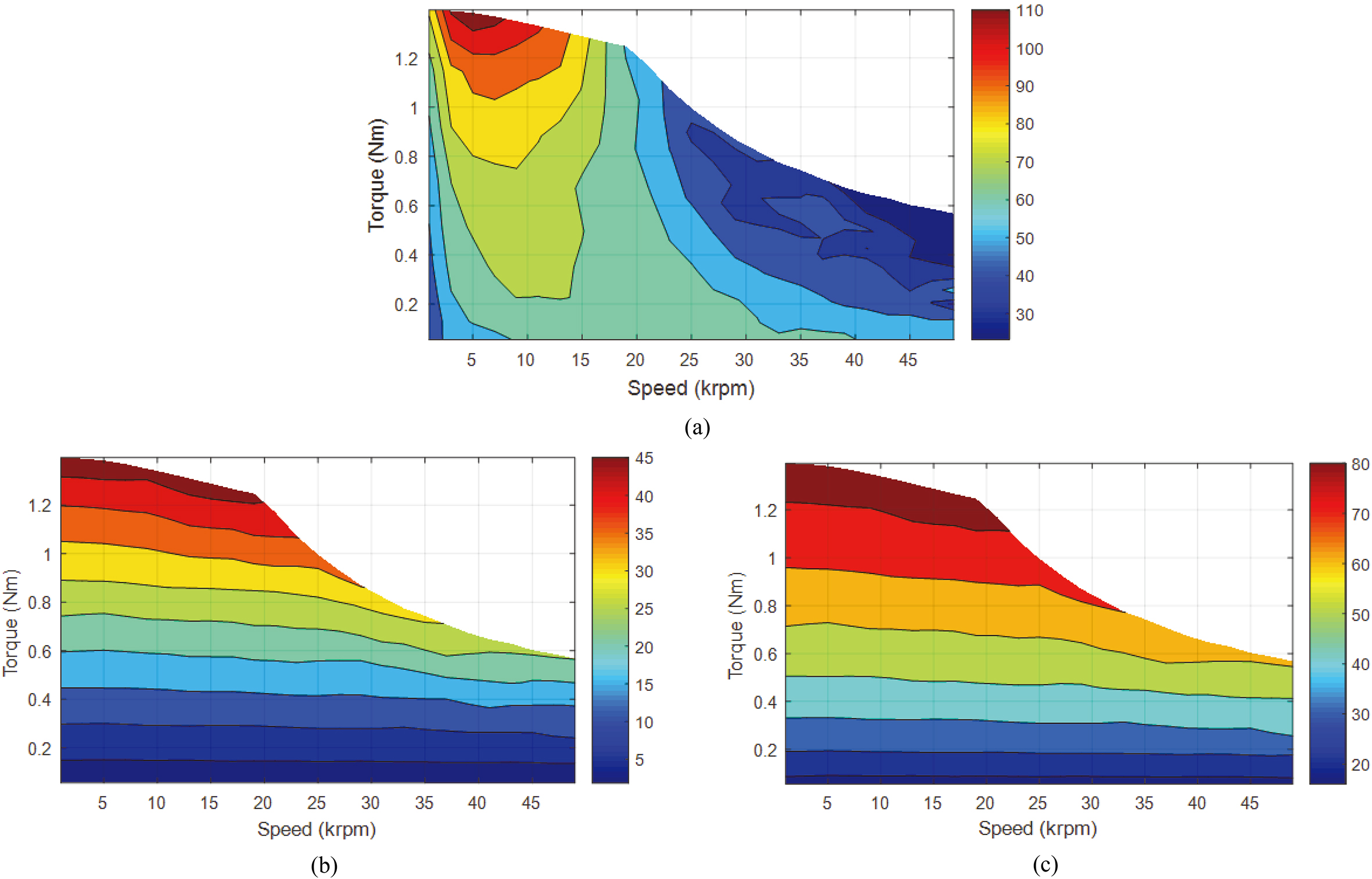
Thermal FEA analysis result of heatsink and power switches for worst thermal case (5 krpm SRM operating speed).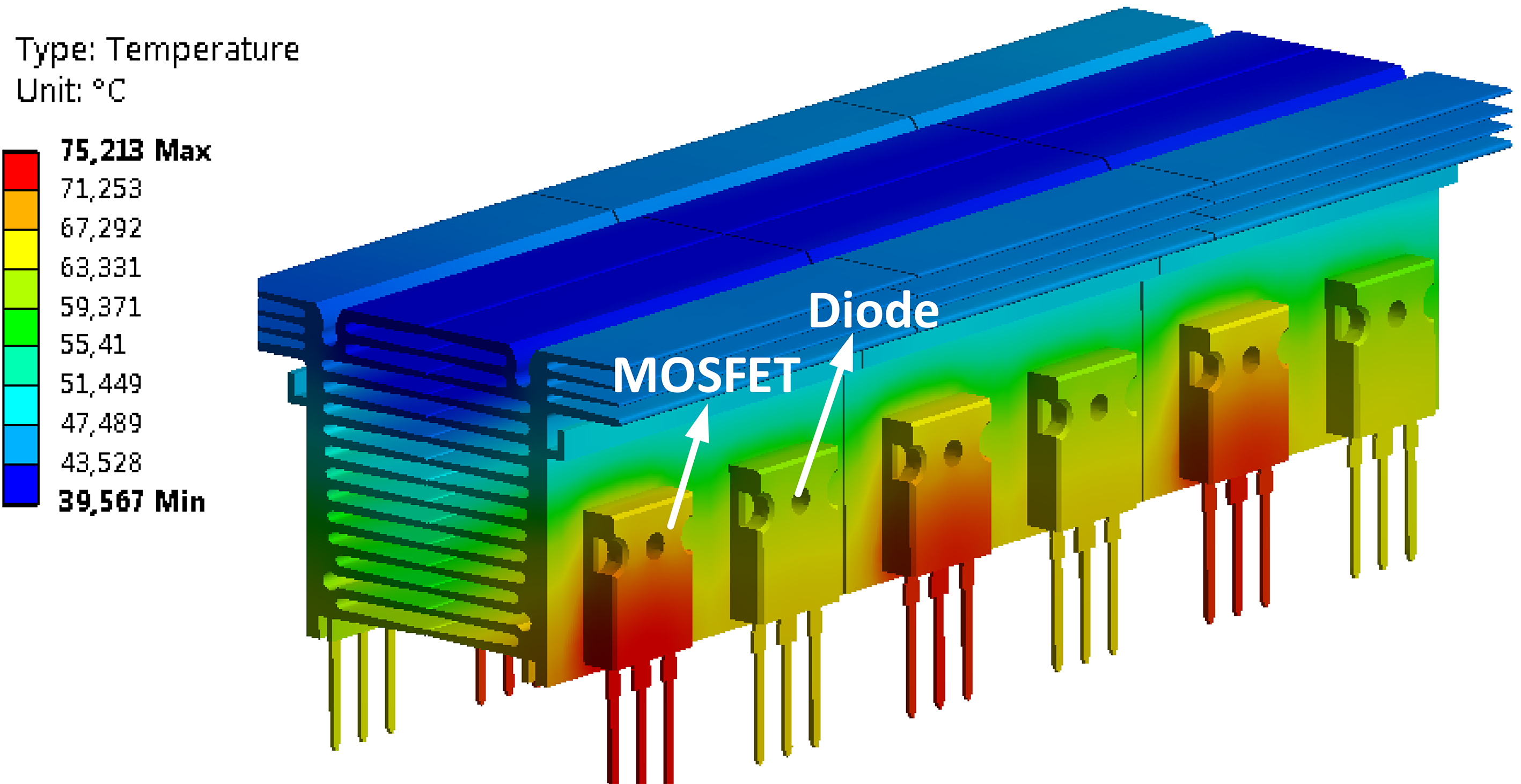
The heat sources in the circuit such as power MOSFETs and diodes are usually used with the heatsink which has some complex geometry. Hence, the thermal analysis is performed using numerical method (FEA) considering diodes, MOSFETs and heatsink as shown in Fig. 20. Two fans are modeled as a heat sink coolant. One of them is air blowing and the other one is air compressing which can remove the warm air quickly. The analysis is done considering the worst case i.e. low speed high phase current (5 krpm, 20 A reference current as shown in Fig. 18a). The results clearly verify selected power semiconductors and heatsink can work safely even at worst cases.
In this paper, three important losses in the high speed switched reluctance machine applications are studied detailed using integrated simulation methods. These three important losses are the copper losses considering skin and proximity effect, iron losses and semiconductor switching-conduction losses. In high-speed electric machines, skin and proximity effects in the coil cause additional winding resistance. Moreover, iron losses on the machine side and the switching losses in the power electronics drive circuit side increase excessively with the high excitation frequency. Especially in the SRM, the iron losses constitute the major part of the losses because of the non-sinusoidal magnetic field in the airgap. In this study, a number of wire in the bundle of the conductor is optimized for electromagnetic field analysis. Core loss analyses are performed with coupled simulation method by applying actual current waveform to the SRM. Electrical losses are calculated for different industrially available power MOSFETs and diodes in drive circuit then optimal devices are determined. Both core loss analysis and switching loss calculation results show that the single pulse mode in the SRM has a considerable advantage on the motor and drive efficiency. Finally, thermal FEA is performed for forced cooled heat sink and selected power switching devices.
Footnotes
Acknowledgments
This study was supported by the Scientific and Technological Research Council of TURKEY (TUBITAK). The Scientific and Technical Research Council of Turkey (TUBITAK) is acknowledged for granting Yusuf Yasa with International Doctoral Research study in the framework of TUBITAK-BIDEB 2214 grant.