
Abstract
In this paper, a novel magnetic circuit network model is proposed for flux calculation on switched reluctance machines (SRM) of double saliency. Specifically, the airgap reluctance is modeled by a topology of paralleled magnetic paths that only depends on geometry and rotor position, while magnetic saturation on poles is modeled by a simple lookup approach. Such network is featured by allowing magnetic coupling effect from multiple phases. The flux linkage and torque generation considering the coupling can be calculated in a fast and accurate way without limit of power density or rotating speed.
Introduction
The magnetic equivalent circuit (MEC) model has been widely used in switched reluctance machines (SRM) to calculate flux linkage characteristics. In such a model, the machine is discretized into poles and yoke sectors that are represented respectively by a lumped magnetic reluctance element [1, 2, 3, 4]. However, the conventional MEC often results in less calculation accuracy, due to the double saliency structure that both stator and rotor have salient poles. As a result, the airgap path varies sharply with rotation [5, 6] and when power density increases, high local magnetic saturation occurs. That saturation distributes at pole tips and varies with rotor position and phase current level [7], serving as part of the magnetic reluctance.
The flux linkage calculation is required of high accuracy upon which further calculation such as torque and loss can be based. To account for such double saliency that leads to high nonlinearity of magnetic circuit, improvements were made. In [8], the airgap reluctance is modeled by a fitting method of polynomial function. However, the polynomial coefficients cannot be accurately obtained without finite element method. In [9] curve fitting is used instead by an exponent function, with coefficients that respectively represent flux linkage when the machine starts saturation, degree of saturation severity and inductance increment under high excitation current. However, higher order harmonics lead to inaccuracy by adding ripple to the predicted instantaneous torque. In [10], the magnetic circuit is calculated according to Ampere’s Law without empirical equations, and the calculation is divided whether the pole pair has alignment. However, calculation accuracy of flux linkage needs improvement by comparing with finite element (FE) method. Such numerical gap with FE is small, but would lead to deviation for further analysis. In [11], the flux tubes are refined according to flux path and calculation shows the desired accuracy. However, the model subjects to complexity when SRM prototype varies. To account for magnetic saturation distribution, variable sizes of magnetic reluctances as a function of rotor position and phase current excitation is applied in MEC [12, 13]. However, the circuit model is complicated in managing the magnetic reluctances. Alternatively direct measurements are used as part of the MEC simulation [14, 15, 16].
Further, magnetic coupling of phases occurs close to the full aligned rotor position where a couple of phase is excited simultaneously. Taking such a point can improve calculation accuracy [17, 18] in flux and torque control. However, most MEC models do not take into account the coupling and only a few are involved [19, 20]. In [19], the coupling effect is taken by adding equivalent airgap reluctance between phases. The elements values can be predetermined by FE analysis or measurement. However, the calculation accuracy needs further discussion if taking a closer comparison with FE, especially close to the aligned rotor position.
This paper proposes a FE assisted MEC network model for salient SRMs with phase coupling. The MEC part is for the rotor position dependent airgap reluctance calculation while the FE part is for magnetic saturation estimation. This paper is structured as follows: In Section 2, the proposed network model is introduced. Specifically, modeling of airgap reluctance and magnetic saturation are described respectively. In Section 3, calculation accuracy in terms of flux linkage is discussed, followed by torque application considering the magnetic coupling.
The MEC-FE model
In SRM operation, each phase is fluxed and defluxed, which is divided by rotor pole pitch. In general, the time to deflux the machine should equal to flux, and it is inappropriate to extend dwelling angle, which will result in reverse torque by residual flux. With speed increasing, the rate of phase current per rotor angular shift is reduced and therefore phase advancing control is applied to flux in advance as well as to reduce residual flux after alignment. At higher speed, phase current will continue, leading to phases being fluxed all the time during commutation. Table 1 shows overview of the studied 3-phase 12/8 SRM for traction application.
Geometry overview of the studied SRM
Geometry overview of the studied SRM
Accordingly Fig. 1 shows flux paths at typical operation conditions. In Fig. 1a, one phase at unaligned rotor position is excited, the magnetic circuit is unlikely to get saturated and airgap reluctance is considered as the main factor. In Fig. 1b, a couple of pole pairs, including the one of defluxing close to the full aligned position while the other pair of fluxing just after the unaligned position, are energized simultaneously. The multi-phase excitation may lead to not only magnetic saturation on poles, but also magnetic coupling between phases. Therefore, phases are related and the degree of dependence is deemed as a function of rotor speed and phase current.
Flux paths overview at typical rotor positions, (a) by one single phase excitation, (b) by two phase excitations with coupling effect.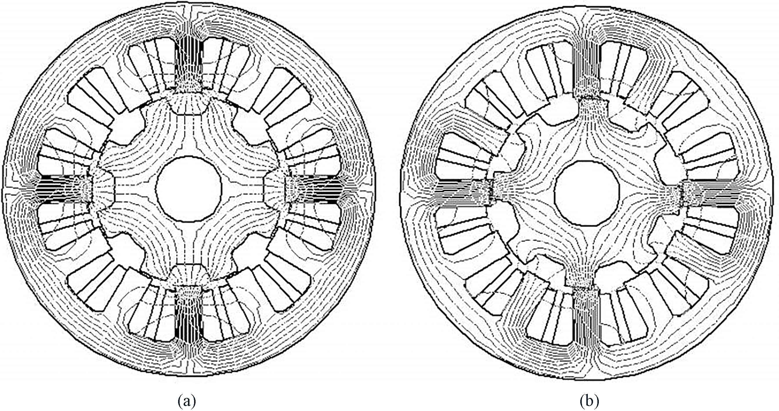
The proposed MEC-FE model is shown in Fig. 2. The stator and rotor part is divided into sectors that each is represented by a lumped magnetic reluctance element, including stator yoke (SY), stator tooth (ST), rotor tooth (RT), rotor yoke (RY). Due to magnetic saturation that predominantly resides at the exciting poles, elements on the stator and rotor teeth are marked with arrows, indicating variability to be determined by lookup approach. Each rotor slot is represented by an element LK for slot leakage.
Overview of the proposed network model.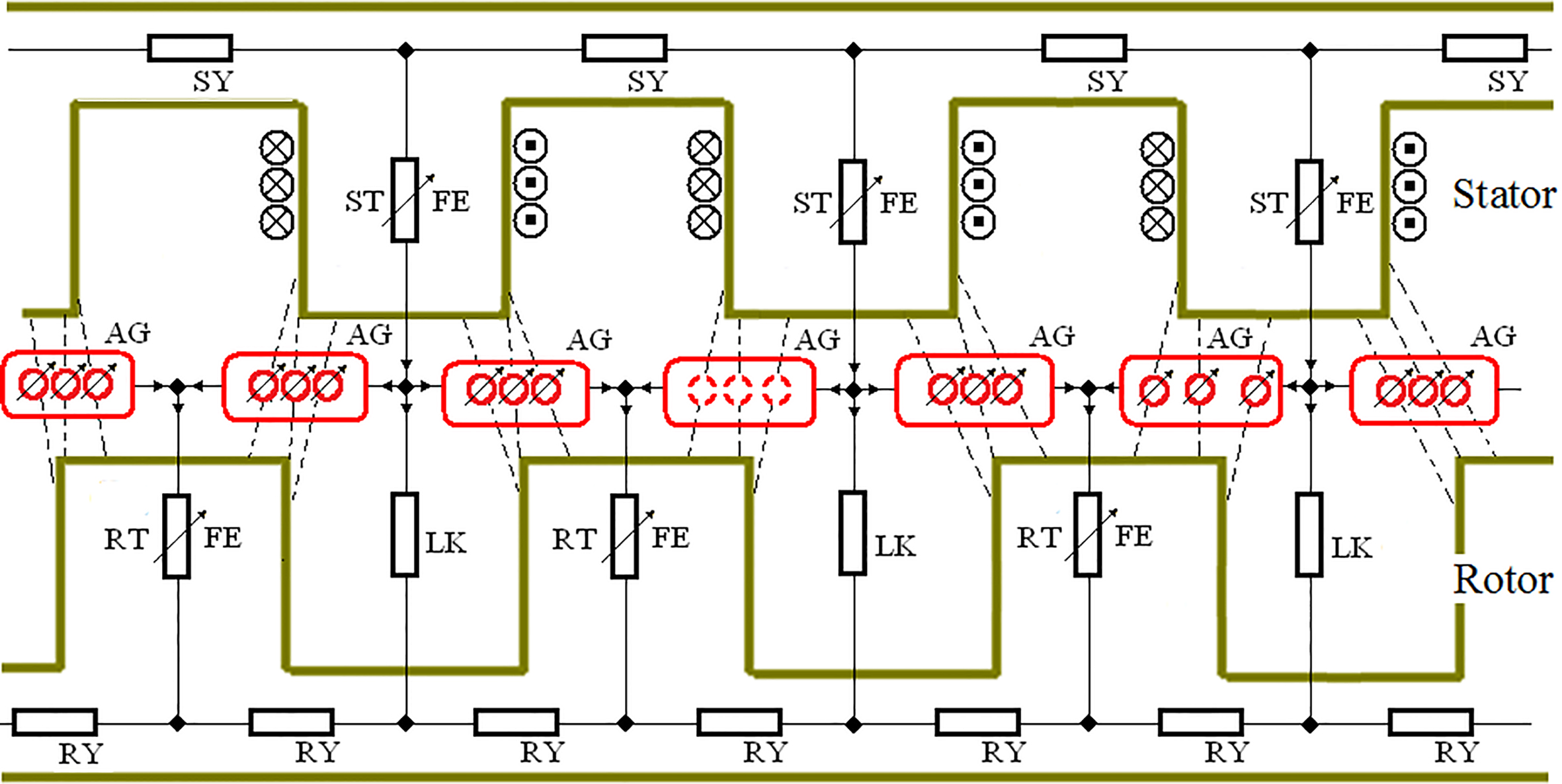
The airgap reluctance (AG) is defined as magnetic connection between a stator and rotor pole pair. The connection is valid from the aligned position till the position when the adjacent pole pair is aligned. That is for one pole pair, the minimum airgap reluctance occurs at its alignment while the maximum occurs at the position when the adjacent pair is aligned. Therefore in Fig. 2, each stator pole has a couple of connections to the previous and next rotor poles. Further for each connection, 3 paralleled branches are shown. The middle branch stands for the tip-to-tip path while both side branches stand for the in-profile paths. For each branch the equivalent reluctance is represented by a ring, and the arrow indicates variability.
Flux path details of airgap connections, showing misalignment and partial overlap of a pole pair.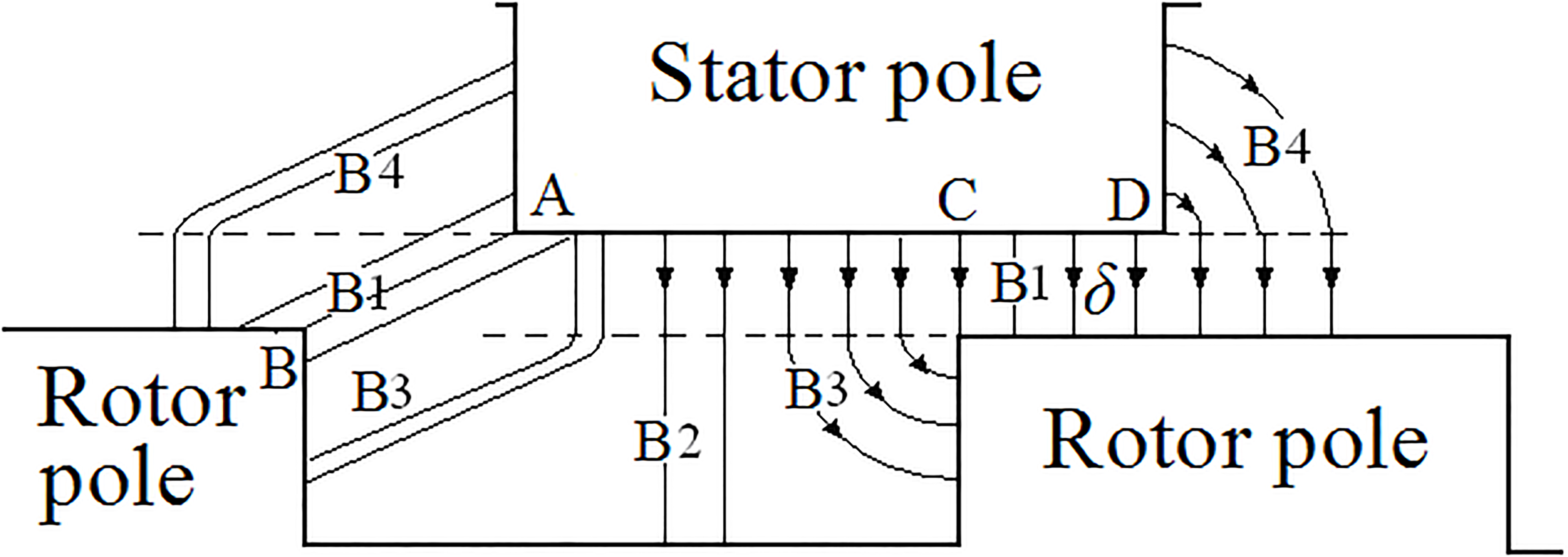
Figure 3 shows the airgap flux path details for the airgap reluctance rings, with typical positons of both misalignment and partial overlap. In either case, airgap paths are modeled by 3 branches B1-B3-B4 and each is represented by a lumped magnetic reluctance element. The reluctance value can be calculated according to the length and width of the regarded airgap path. When poles are not aligned, B1 refers to the shortest distance between the stator and rotor pole tips. The length of B1 is determined by such shortest distance while the width is by a fitting approach [21]. B3 refers to the side path through rotor slot. The length is determined by the straights both in airgap and rotor slot while the width is by comparing with slot leakage path B2 according to the magnetic circuit principle. B4 path can be seen symmetrical to B3. When poles are partially aligned, B1 refers to the overlap airgap zone and the path is determined by airgap length
Besides airgap, magnetic saturation as another source of reluctance affects flux linkage curves. The saturation serves as a function of phase current excitation, as well as rotor position that depend on airgap path. It is assumed that the degree of saturation is quantifiable and this paper uses a lookup approach to identify the value in the form of the permeance drop
To make the lookup for magnetic saturation dimensionless, which means adaptability to variation of machine geometry, how to model the rotor positon with minimum variables is described. When poles are not aligned, rotor position is represented by the length AB in Fig. 3 that the main part of flux lines is going through airgap. Here it is defined as distance
Now for both cases, the permeance drop
The permeance drop lookup function obtained from FE, (a) non-overlapping; (b) at partial and full overlapping.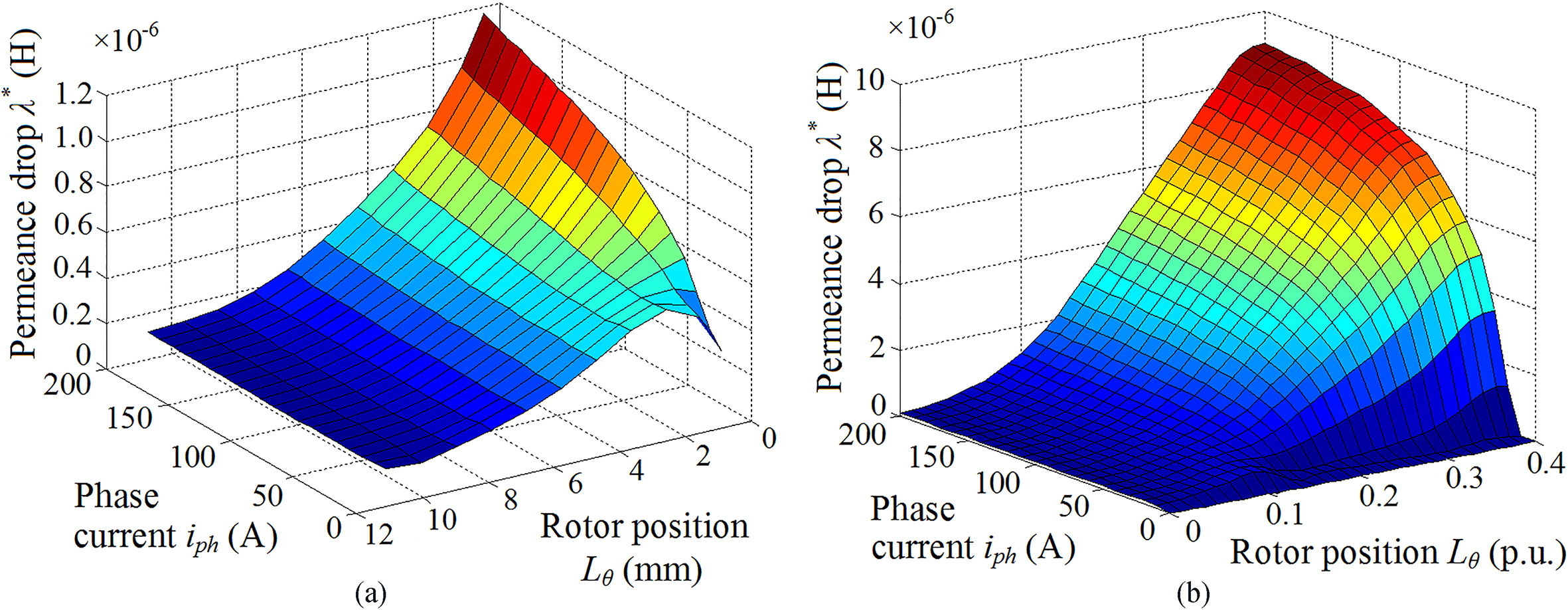
The permeance drop is modeled by a 3D lookup. Figure 4 shows the map at non-overlap and overlap rotor positions respectively. Note that the lookup applies to the machine with number of turns per pole
The flux linkage under selected rotor positions without magnetic coupling.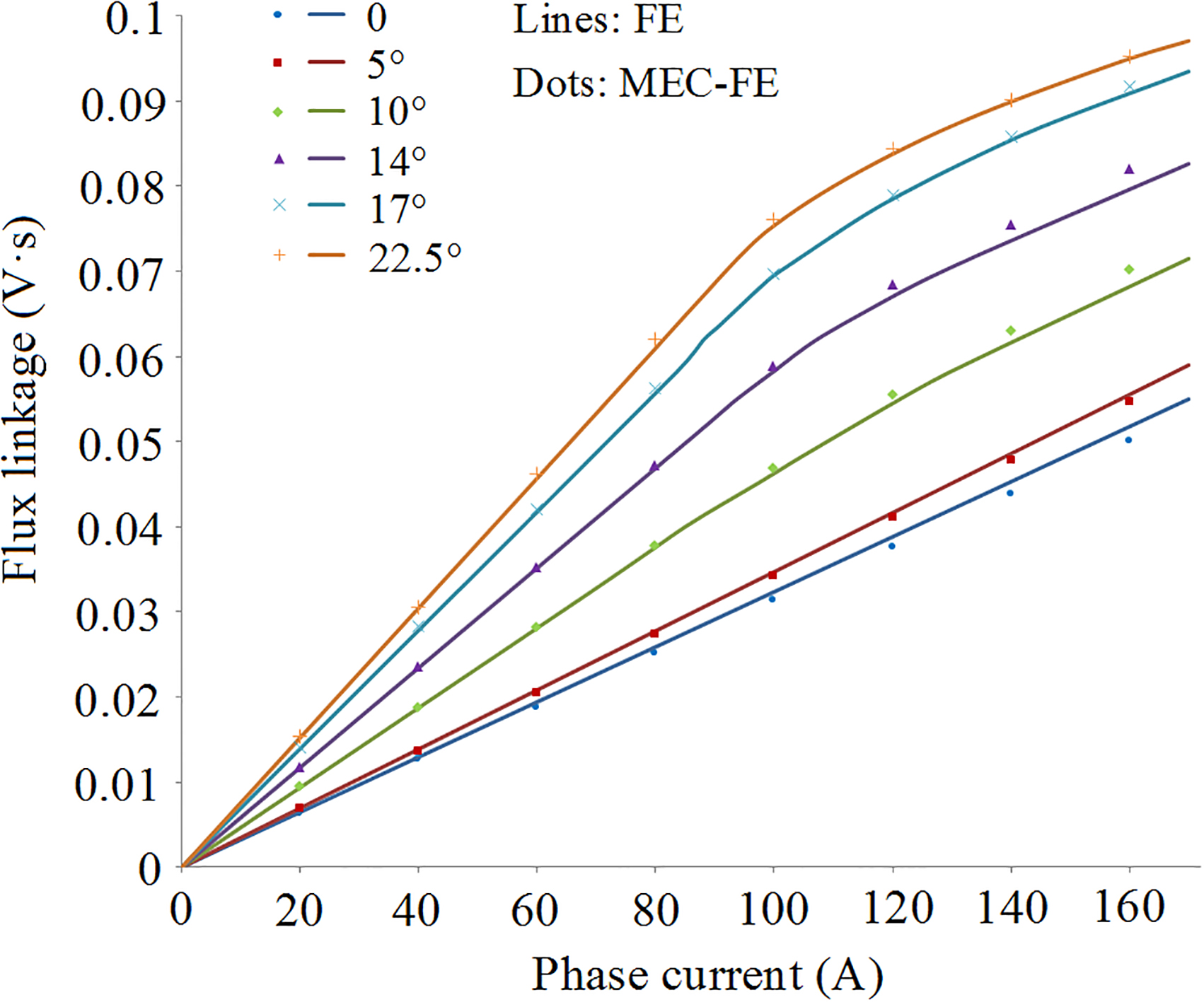
Comparison of flux linkage curves under selected rotor positions, with and without magnetic coupling between phases.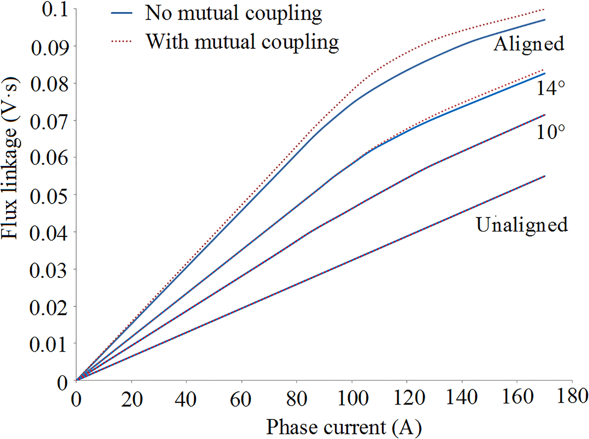
Comparison of flux linkage variation due to the coupling effect, where different levels of current are applied.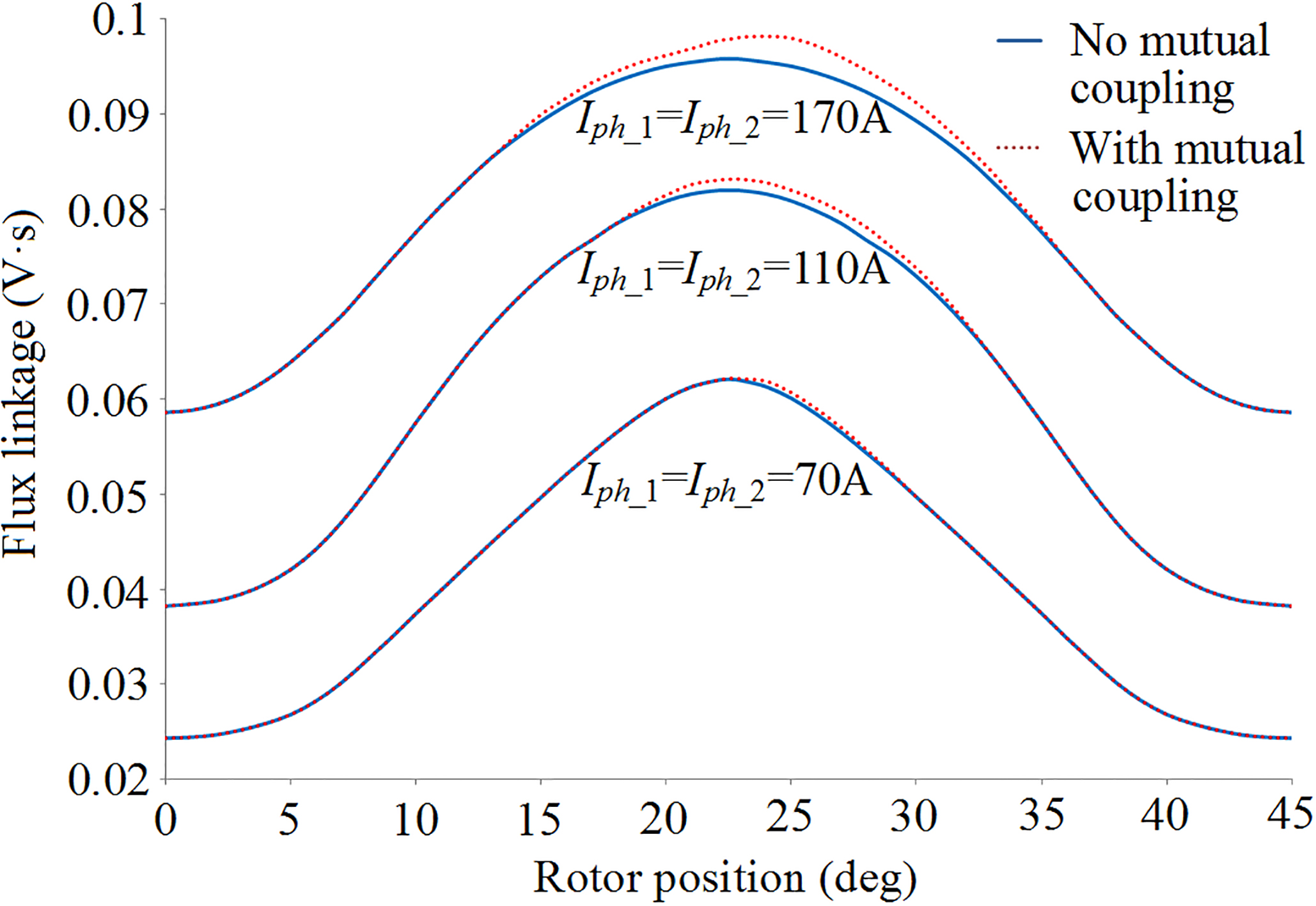
The flux linkage curves of the studied machine by one single phase excitation at selected rotor positions are comparatively shown in Fig. 5, with a wide current range till 170 A. Note that 0
Further Fig. 6 comparatively shows magnetic coupling effect at selected rotor positions. At unaligned 0
The magnetic coupling is further discussed. Figure 7 shows flux linkage variation under full rotor position range at selected levels of phase current
Geometric variation (in %) from the studied SRM as M0
The magnetic coupling effect due to variation of airgap length, where M1 and M2 are simulated, with M0 as reference; Note that 22.5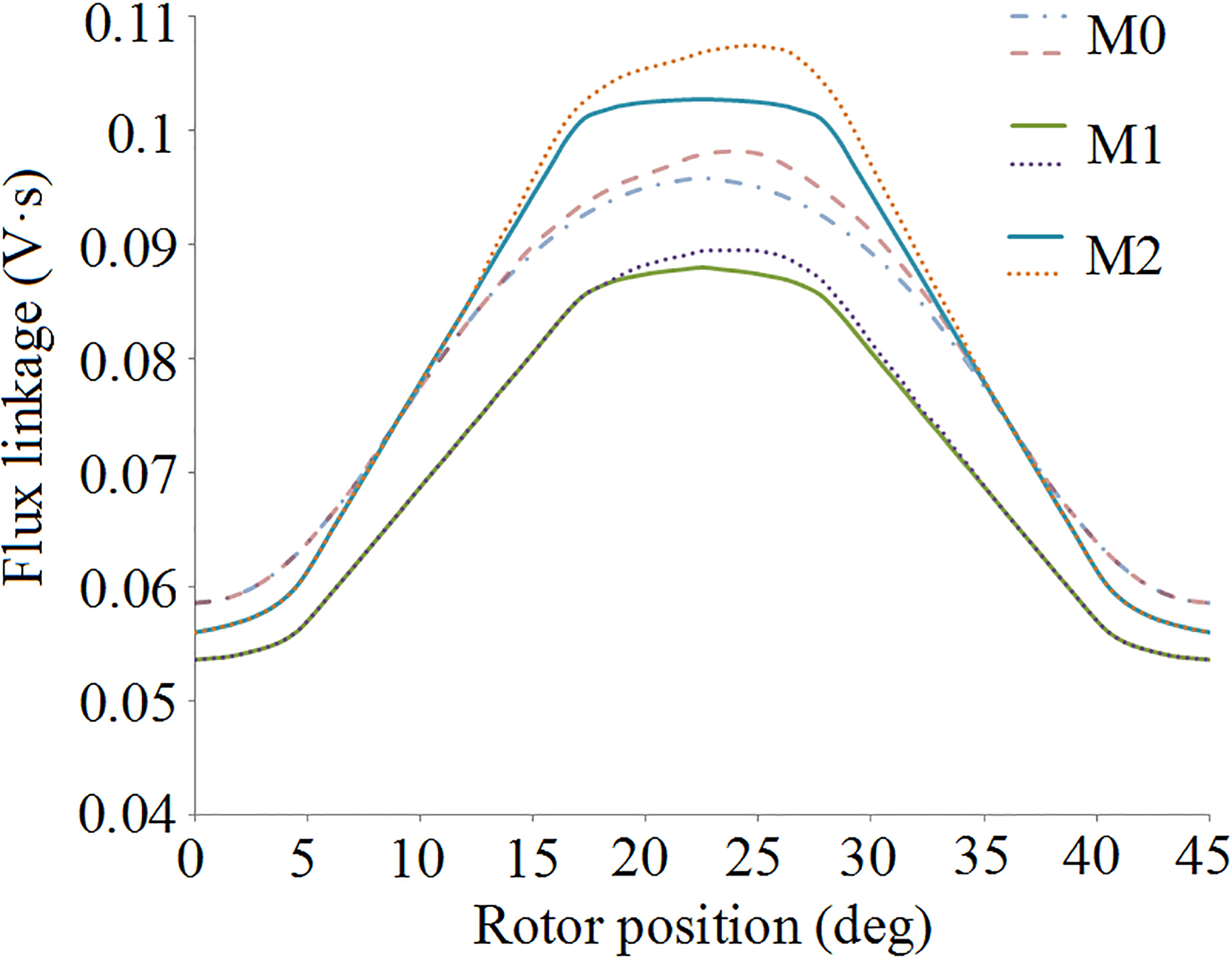
The model adaptability is verified by simulating typical SRMs of main geometric parameter variation. Table 2 shows the variation, including airgap length
Figure 8 shows flux linkage due to variation of airgap length (M1 and M2). The values decrease with a higher airgap length, especially close to 22.5
The magnetic coupling due to variation of pole widths where M3 and M4 are simulated, with M0 as reference; Note that 22.5
The magnetic coupling effect due to stator yoke widths where M5 is simulated, with M0 as reference; Note that 22.5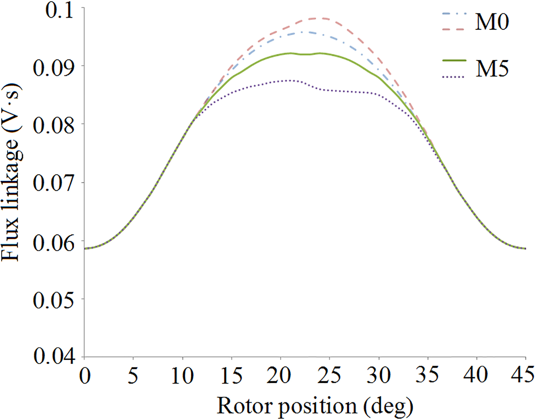
Figure 9 shows flux linkage due to variation of pole width. In M3, width of rotor pole is reduced by 20%, followed by M4 that the stator pole width is further reduced by 20%. It is found that the values at any rotor position are reduced in M3, and further sharply reduced in M4. Also, the peak width of the curves is narrowed with reduced pole width. However for each machine M0, M3 and M4, the numerical discrepancy due to the magnetic coupling remains similar. This is because nearby the aligned positon 22.5
Figure 10 shows flux variation due to stator yoke thickness. It is found that M5 values by reducing 25% yoke thickness, is reduced. This is due to the narrowed yoke that leads to magnetic saturation that weakens active flux. Regarding the magnetic coupling in M5, discrepancy happens in particular around 22.5
This paper proposes a FE assisted magnetic circuit model for SRMs, including phase coupling effect. The airgap reluctance is modeled by equivalent paths of simple geometric relations without empirical estimation. To account for local magnetic saturation, a fast FE lookup method is proposed, which can be applied to various machine geometries without power limit. The amount of computation is quite competitive compared with FE. Further this model can effectively simulate magnetic coupling effect between phases. It is shown significance the magnetic coupling affects flux and therefore the design can be better predicted under various control modes.
Footnotes
Acknowledgments
This work is supported by the Natural Science Foundation of China (51607180). The authors gratefully acknowledge Institute of Electrical Drives and Actuators (EAA), University of Bundeswehr Muenchen, Germany, for their support in this research.