
Abstract
In this article, a clear and concise analytical method for predicting the performance of a Liquid-cooling eddy current brake (LC-ECB) is proposed. The LC-ECB has a coolant channel in the rotor to allow direct cooling of the inner surface of the stator. The static air-gap magnetic field distribution is obtained by the dynamic magnetic equivalent circuit (MEC) method, and the magnetic flux leakage and global magnetic saturation effects are fully considered. The magnetic field intensity distribution function of the eddy current reaction magnetic field is derived for the first time based on Ampere circuital theorem. Considering the local magnetic saturation and skin effect, a novel double-iteration algorithm based on the conservation principle of magnetic pressure drop is applied to obtain the transient air-gap flux density distribution, and then the brake torque expression is obtained. The finite element method (FEM) and experimental results show that the proposed method is feasible and effective. The new model is easy to program and can be easily used in the initial design and optimization of LC-ECB.
Keywords
Introduction
The eddy current brake (ECB) is widely used in heavy-duty vehicles and can significantly extend the life of friction braking systems and improve driving safety [1,2]. An ECB is essentially an energy conversion device that converts mechanical energy into heat based on the principle of eddy currents. When working for a long time, the eddy current-induced heat increases the overall temperature of the eddy current region and ECB, and the conductivity of the excitation coil and the permeability of the eddy current region decrease with an increase in temperature, resulting in a decrease in the braking torque, which is called thermal recession [3,4]. Clearly, liquid cooling has a better heat-dissipation effect than air cooling, which can effectively reduce the thermal recession of the ECB. In recent years, various liquid-cooling eddy current brakes (LC-ECB) have been proposed in our previous studies [2,5,6].
In the preliminary design and optimization process of LC-ECB, it is necessary to have a concise and accurate theoretical model to quickly study the effects of geometrical parameters. There are usually two methods to achieve quantitative analysis of LC-ECB, namely numerical and analytical methods. The former refers to the finite element method (FEM), which is generally regarded as an effective method for obtaining accurate air-gap magnetic field distribution and braking torque through software-assisted calculation and is suitable for complex shapes. However, this method is time-consuming. In addition, in the process of optimization, the model must be established and recalculated many times as the structural parameters change, which is usually unacceptable in engineering. The latter analytical method requires less computation, depends on the structural parameters of LC-ECB, has a clear physical meaning, and is more suitable for the initial design and optimization of LC-ECB.
Popular analytical methods for electromagnetic devices include magnetic field analysis,magnetic equivalent circuit (MEC) [7], or equivalent magnetic network (EMN) methods [8]. Schwarz-christoffel (SC) mapping [9]and the sub-domain model (SDM) [10,11] are commonly used magnetic field analysis methods that are derived from Maxwell’s equations and have clear physical significance. Based on a reasonable boundary condition setting, partial differential equations must be solved, and the calculation process is complicated. Additionally, the magnetic saturation effect is generally ignored [12]. The latter MEC method is less difficult, and the effects of magnetic leakage and magnetic saturation can be considered [13,14].
Some scholars have applied analytical approaches to model the ECB. [15] proposed a 2-D Fourier transform model and compared the analytical results with the FEM and experimental results, proving the effectiveness of the method. The calculation error of this method is large at high speeds, and the influence of the skin effect is ignored. [16] derived the expressions of the braking torque and normal force based on the magnetic field calculation method for the axial magnetic flux ECB. However, the model must solve Poisson’s equations, and the calculation process is complicated. [17] studied a self-excited LC-ECB. The static magnetic field was analyzed by the MEC method, and the transient air gap magnetic field distribution and skin effect were analyzed by numerical methods. However, the analytical method was not used. In our previous research, all the calculation models of braking torque were required to solve the difference equation. In addition, the distribution of the transient air-gap magnetic field at different speeds is not provided. Reference [6] established an analytical model of the permanent magnet ECB braking torque, which provided the distribution of the transient air-gap magnetic field and considered the skin effect on braking performance. However, the parameters were obtained using a numerical fitting method, and the difference equation still needs to be solved in the calculation process. In summary, few studies have conducted thorough research on the transient air-gap magnetic field distribution of the ECB, and the air-gap magnetic field distribution is very important in calculating braking torque and analyzing braking performance.
In this study, a novel LC-ECB with dual salient poles is investigated. The ECB has designed an internal water channel on the rotor, which can directly cool the heating surface and significantly reduce thermal recession during braking. A concise analytical calculation method for the LC-ECB transient air-gap magnetic field distribution and braking-torque prediction was proposed. The static air-gap magnetic field distribution is obtained using the dynamic EMC method, and the magnetic leakage and global magnetic saturation effects are fully considered. A piecewise smoothing function was used to calculate the static magnetic-field distribution more accurately. The magnetic field intensity distribution function of the eddy current reaction magnetic field is derived based on the ampere circuit theorem in the 2-D model. In particular, considering the local magnetic saturation and eddy current skin effect on the inner surface of the stator and rotor teeth, a novel double-iterative algorithm is used to obtain the transient air-gap magnetic field distribution at different speeds, and then the braking torque expression is derived. Compared with FEM, this analytical calculation method greatly reduces the calculation time and is particularly suitable for the initial design and optimization of LC-ECB. Furthermore, the analytical calculation method of the transient air-gap magnetic density distribution and transmission torque is also applicable to the analysis of eddy current couplers.

The structure of the LC-ECB. (a) 3/4 Model of LC-ECB. (b) 1/16 Electromagnetic model of LC-ECB.
The 3/4 model of the new LC-ECB is shown in Fig. 1(a), where the end cover, bearing, and other accessories are omitted. The electromagnetic part of the LC-ECB is a double-salient-pole structure consisting of a stator, rotor, and excitation coil. The material of the stator and rotor is low-carbon steel with high magnetic permeability. The red arrows in Fig. 1(a) indicate coolant flow. The cooling liquid was directly sprayed onto the inner surface of the stator through the cooling pipe, rotor impeller, and rotor oil passage. Because the braking power is converted into an eddy current on the inner surface of the stator to generate heat, direct cooling of the inner surface of the stator can achieve a better cooling effect and effectively reduce the thermal recession of the brake. Figure 1(b) shows the 1/16 electromagnetic model of the LC-ECB. When the coil is energized, a circular magnetic field is generated around the coil. The orange arrow in the figure indicates the direction of the magnetic field lines. Salient poles are distributed on the outer ring on both sides of the rotor, which plays the role of gathering the magnetic field. The magnetic induction intensity on the inner surface of the stator was alternately distributed in the order of strong and weak in the circumferential direction. When the rotor rotates, a changing magnetic field is generated on the surface of the stator. According to Lenz’s law, a changing magnetic field on the stator generates eddy current. According to the principle of the skin effect, an eddy current is generated on the inner surface of the stator, which is accompanied by the generation of resistance heat. The eddy current on the stator excited the induced magnetic field, and the induced magnetic field inhibited the change in the original magnetic field, which inhibited the rotation of the rotor, thereby generating a braking torque.
Assumptions
To simplify the complexity of eddy current analysis under transient conditions and improve the availability of the model, the factors that have little impact on the calculation accuracy of the model were simplified, and the following assumptions were made:
The main magnetic flux passes vertically through the upper surface of the rotor teeth, the air gap, and the inner surface of the stator, and the magnetic leakage between a pair of salient pole teeth and between the salient pole teeth and stator is considered. It is assumed that the conductivity and permeability of the stator and excitation coil are not affected by temperature. The material characteristics of the rotor and stator are uniform; therefore, the eddy currents generated by each salient pole are the same at a certain speed. The magnetic permeability of the rotor and stator conforms to the B-H curve of the material.
Static magnetic field model considering general saturation
An LC-ECB is essentially a 3-D rotating electromagnetic device. To obtain higher calculation accuracy, a cylindrical coordinate system is used in the static magnetic field calculation. Naturally, the curvature effect can also be considered. The LC-ECB, which comprises 16 pairs of salient pole teeth, exhibits a high degree of symmetry. As illustrated in Fig. 1(b), it is possible to obtain the static electromagnetic characteristics of the entire LC-ECB by analyzing only a single representative model, representing 1/16th of the complete structure. As shown in Fig. 2, The equivalent magnetic circuit of the 1/16 model and the reluctance of each part are marked. The main parameters are listed in Table 1. The MEC model is illustrated in Fig. 3. The coil excitation is equivalent to the magnetomotive force F c , and the air-gap reluctance and magnetic leakage reluctance between the salient pole teeth and stator are equivalent to the total air-gap reluctance R g . Owing to the existence of flux leakage R fc between salient teeth, the MEC model includes two magnetic circuits with magnetic fluxes of Φ1 and Φ2.
The excitation magnetomotive force (MMF) F
c
generated when the coil is energized is given by:
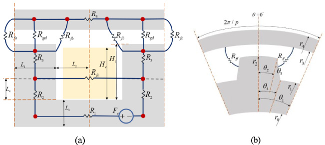
Structure and MEC model of the LC-ECB. (a) Cross-sectional view. (b) Left view.
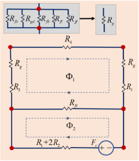
MEC model.
Main specifications of analysis model
In the main magnetic circuit, rotor reluctance R
1, R
2, R
3 stator reluctance R
4, and air gap reluctance R
gd
can be expressed as:
In addition to the main magnetic flux of the air gap, the magnetic leakage between the surrounding surface of the tooth and the stator cannot be ignored. Where the magnetic leakage reluctance R
ff
between the two sides of the salient pole tooth and stator is expressed as:
The magnetic flux leakage reluctance R
fa
on the outer side and the magnetic flux leakage reluctance R
fb
on the inner side of the salient tooth are expressed as:
The total reluctance between the salient pole teeth and stator is equivalent to the total air-gap reluctance R
g
, which can be expressed as:
According to Ampere’s law, the magnetic field intensity H
x
between a pair of teeth is a piecewise function that can be expressed as:
Magnetic flux leakage energy E can be expressed as:
V is the slot air-gap volume. According to (12) and (13):
The magnetic field energy can also be expressed as:
By combining Eqs (14) and (15), the expression of the leakage magnetic reluctance between the teeth can be obtained.
Finally, according to the MEC model shown in Fig. 3, the KVL law was applied to list the magnetic circuit equations for each circuit.
Solving Eq. (17) to obtain the air-gap magnetic flux Φ1, the static air-gap magnetic flux density B
sg
can be obtained as follows:
In some studies, it was assumed that the static air gap flux density B
sg
is distributed as a square wave [12] or sine wave [18] in the circumferential direction. The static air-gap flux density distribution is not a square wave because of the edge leakage flux. To improve accuracy, a piecewise function is introduced in the circumferential direction to smooth the static air-gap flux density distribution. Expressed as:
To obtain a sufficient braking torque, the static air-gap flux density should be sufficiently large. Therefore, when the coil is energized, all parts of the brake are generally saturated, which is called global magnetic saturation. The tooth end and inner side of the stator were in deep saturation, as shown in Fig. 4. To consider the influence of global magnetic saturation, a nonlinear iterative algorithm was introduced to update dynamic permeability. The relative permeability μ r1, μ r2, μ r3, μ r4 changes with the flux density B. The B −μ curve of the material was obtained from the B − Hcurve of the material in Fig. 5(a), as shown in Fig. 5(b).

Global magnetic saturation.
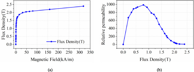
(a) B − H curve of 20# steel. (b) B −μ curve of 20# steel.
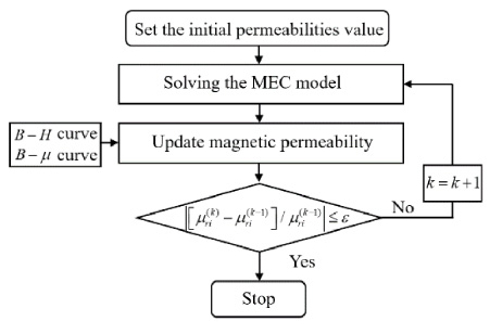
The iterative calculation process is illustrated in Fig. 6. First, the initial permeability of each part is given, and then the magnetic flux Φ1 and Φ2 are solved using the above MEC model to obtain the magnetic density of each part. According to the B −μ curve of a ferromagnetic material, the new permeability can be updated as follows [19]:
k is the iteration number, and d is a damping constant set to 0.1 herein [12].
The conditions for stopping the iterative process are:
Flowchart of the nonlinear MEC.
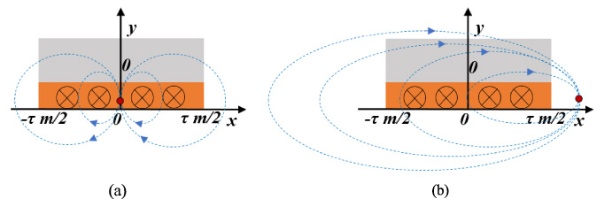
When the brake is operating, the eddy current reaction magnetic field interacts with the original magnetic field to generate braking torque. Owing to the skin effect, eddy currents exist only on the inner surface of the stator, which is called the eddy current layer. In [10], the effect of the eddy current reaction magnetic field is ignored. Reference [18] uses empirical parameters to convert the mean eddy current value to the reactive magnetic field strength. None of the above methods can obtain the transient air-gap magnetic density distribution, nor can they clearly reveal the interaction mechanism between the reactive magnetic field and the original magnetic field. In addition, the analytical model based on the subdomain method has difficulty dealing with the magnetic-saturation effect. In this study, a calculation model for the eddy current reaction magnetic field based on the ampere circuit theorem is proposed. To facilitate the study of the distribution of the reaction magnetic field, the brake was expanded circumferentially, and the Cartesian coordinate system model was established. As shown in Fig. 7, an eddy current was generated on the inner surface of the stator corresponding to the tooth surface, assuming that the depth of the eddy current layer was the skin depth. τ m is the circumferential length of the tooth. τ p is the circumferential polar distance. When the rotor moves in the direction of the orange arrow in the figure, the eddy current layer produces a current perpendicular to the paper surface. The green arrow indicates the magnetic field direction. It can be seen that, owing to the effect of the eddy current reaction magnetic field, the magnetic field at the front of the rotor teeth is weakened, and the magnetic field at the rear is strengthened.

2-D electromagnetic model of the LC-ECB.
To describe the reaction magnetic field generated by the eddy current clearly, as shown in Fig. 8, it is assumed that there are four current beams in the eddy current region corresponding to tooth 0. As shown in Fig. 8(a), the magnitude of the reaction magnetic field at a point in the eddy current region is a superposition of the magnetic fields generated by the current beams on the left and right sides of this point. For a point outside the eddy current region, as shown in Fig. 8(b), the magnetic field strength at this point is the superposition of the magnetic fields generated by all currents in the eddy current region.
Reaction magnetic field model. (a) In the eddy current region. (b) Outside the eddy current region.
In fact, the current bundle can be regarded as infinite, and the eddy current density along the x direction in the eddy current region is not uniform, which is a function of x and can be expressed as:
In addition, considering the skin effect, the thickness of the eddy current layer is also a function of x, which can be expressed as:
ω e where is the electrical angular velocity, h s is the thickness of the stator, and μ r (x) is the relative permeability distribution in the eddy current region, which conforms to the B −μ curve.
According to the Ampere circuital theorem, the intensity distribution of the reaction magnetic field generated by the eddy current region corresponding to the 0th tooth can be expressed by the following piecewise integral function:
Owing to this symmetry, other rotor teeth corresponding to the magnetic field intensity distribution in the eddy current region are also easily obtained.
From the above analysis, because of the eddy current reaction magnetic field, the magnetic field at the front of the rotor tooth is weakened and the magnetic field at the rear is strengthened, resulting in strong magnetic saturation at the rear of the rotor tooth tip and its corresponding inner surface of the stator, which is called local magnetic saturation [20]. As shown in Fig. 9.
We observed that local magnetic saturation occurred only on the rotor tooth tips and the inner surface of the stator. According to Kirchhoff’s law, it can be considered that the magnetic pressure drop at the rotor tooth tip and rotor inner wall is conserved under the conditions of global magnetic saturation and local magnetic saturation.

Local magnetic saturation.
According to ((21)), the magnetomotive force (MMF) of the reaction magnetic field F
e
(x) is
Because the transient air-gap magnetic field is a dynamic change process, the original magnetic field and the eddy current reaction magnetic field reach a dynamic balance; that is, the ability of the original magnetic field to generate eddy currents and the influence of the eddy current reaction magnetic field on the original magnetic field are balanced. However, this balance cannot be calculated directly. In this study, a double-iterative algorithm is proposed based on the conservation of the local magnetic pressure drop to calculate the transient air-gap magnetic field distribution. The flow of the algorithm is shown in Fig. 10. First, the static air-gap distribution at the global magnetic saturation obtained by the nonlinear MEC model was used as the initial condition. In addition, we initialized a small velocity and assumed that the eddy current density distribution generated at the initial velocity was uniform. The first iterative process involves calculating the new magnetic pressure drop at each speed, updating the magnetic flux density and permeability, and recalculating the magnetic pressure drop until the convergence condition is satisfied. The second iterative process updates the speed and recalculates the new magnetic pressure drop. In this algorithm, the thickness distribution of the eddy current layer changes during the iterative process, and the skin effect is considered.
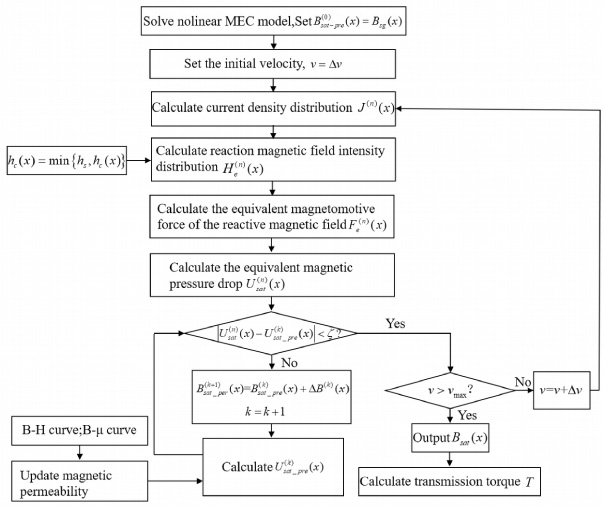
Flowchart of the double-iteration algorithm.
The braking torque can be calculated after obtaining the transient air-gap flux density and eddy current density distribution using the above iterative algorithm. The braking torque T can be calculated from the eddy current power losses P of the stator:
Considering the real path of the eddy current, the direction of the eddy current is not parallel to the tooth edge but a circular path, as shown in Fig. 11. Therefore, radial edge effects cannot be ignored [21]. The Russell-Norsworthy factor was introduced to correct the torque calculated by the 2-D model [22]. Because the end of the eddy current ring is a thick stator shell, which can be regarded as a zero-resistance end-ring, the overhang coefficient 𝜆
′
is:
After correction, the transmission torque T
′
can be calculated by:
To verify the feasibility and effectiveness of the proposed model, the LC-ECB case study assumed that the maximum design speed was 3000 rpm, the number of coil turns was 100, and the rated current was 100 A. The main parameters are listed in Table 1. The materials of the rotor and stator were 20#steel, and the coil was a square copper flat wire.
Real path of the eddy current.
The analytical model calculation results were compared to the 3-D FEM results. Figure 12 shows the 1/16 model and mesh of the research model solved using JMAG-Designer 16.0. The rotor mesh size was 3 mm. To further improve accuracy, the stator mesh size was set to 1 mm. The model has a total number of nodes of 163269 and a total number of elements of 935904.
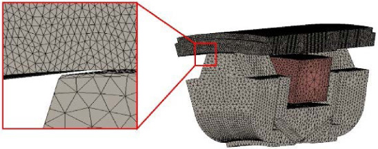
Mesh of the model studied.
Figure 13 shows a comparison of the static air gap flux density distributions predicted analytically and those obtained using the 3-D FEM at different currents. It can be seen that as the excitation current increases, the air gap static magnetic field flux density increases. The nonlinear EMC model considering global magnetic saturation is in good agreement with the 3-D FEM results. Piecewise smoothing functions make the static air-gap distribution calculations more accurate. Because the analytical model does not consider the flux leakage between the tooth root and stator, the error increases at the tooth root. With the increase of excitation, the magnetic leakage between the root and the stator increases. When the current was 100 A, the leakage flux density at the root of the tooth was only approximately 0.25 T, which had little effect on the braking torque and eddy current distribution.
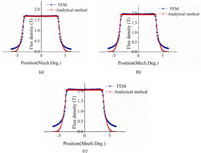
Comparison of static air gap flux density distributions predicted analytically and by the 3-D FEM. (a) I = 30 A. (b) I = 50 A. (b) I = 100 A.
The proposed analytical computational model relies on circumferential flux-density distribution B r (x). The transient air-gap magnetic flux density distributions calculated by the analytical methods and 3-D FEM are compared, as shown in Figs 14 and 15. In the 3-D FEM, the air-gap flux density at the circumferential angle 0° < θ < 90° at the middle of the rotor teeth is considered. To prove that the analytical model has a high calculation accuracy under different excitations and rotational speeds, four cases were selected for verification.
Figure 14 shows a comparison of the air gap flux density distribution at 100 A excitation and at 500 rpm and 1500 rpm. Figure 15 shows a comparison of the air-gap flux density distribution when the rotating speed is 1000 rpm and the excitation current is 30 A and 50 A respectively. It can be observed that the magnetic flux density distribution calculated by the analytical method is in good agreement with the 3D-FEM result curve. Owing to the influence of the eddy current reaction magnetic field, the air-gap magnetic field in front of the rotor teeth is weakened, and the rear magnetic field is strengthened. As shown in Fig. 14, when the excitation current remained unchanged, this phenomenon became more obvious as the speed increased. Although the magnetic field at the rear end of the rotor teeth is strengthened by the eddy current reaction magnetic field, the air-gap magnetic field is generally weakened owing to the serious local magnetic saturation.
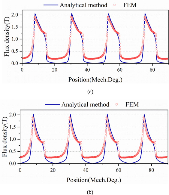
Comparison of transient air gap flux density distributions predicted analytically and by the 3-D FEM. (I = 100 A). (a) n = 500 rpm (b) n = 1500 rpm.
As shown in Fig. 15, when the rotational speed was 1000 rpm, the excitation current affected the overall air-gap flux density. Owing to the eddy current reaction magnetic field, the magnetic field at the rear of the rotor teeth is strengthened, and the magnetic field at the front is weakened. In addition, we found that to obtain a sufficiently large eddy current intensity, the greater the excitation, the greater the eddy current intensity generated when the original magnetic field and the eddy current reaction magnetic field reach a dynamic balance. It can be seen from Figs 14 and 15 that the calculation error of the air-gap flux density corresponding to the tooth root increases with the increase in excitation because the analytical method ignores the magnetic flux leakage between the tooth root and stator. As the eddy current is mainly generated in the stator area corresponding to the end face of the tooth, the magnetic flux leakage at the root of the tooth has little effect on the torque characteristics and can be ignored.
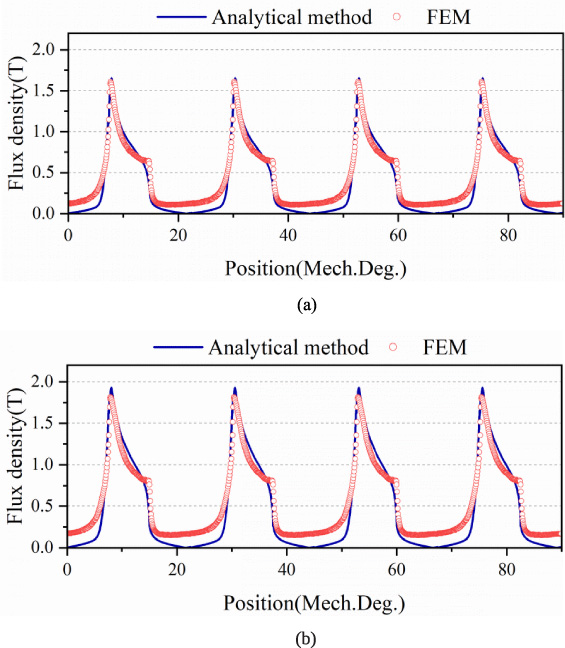
Comparison of transient air gap flux density distributions predicted analytically and by the 3-D FEM. (n = 1000 rpm). (a) I = 30 A. (b) I = 50 A.
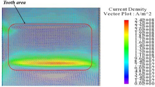
The proposed analytical method considers skin effects. It can be seen from Eq. (24) that the electrical angular velocity ω e and the relative permeability μ r (x) affect the skin depth. Figure 16 shows the calculated skin depth distribution when the excitation is 100 A and the rotational speeds are 500 rpm and 1500 rpm, respectively. The circumferential angle corresponding to one rotor tooth end-face was 7.292°. Figure 16 shows the circumferential skin depth corresponding to one rotor tooth end face on the stator. It can be seen from the figure that the higher the rotation speed, the smaller the skin depth. In addition, the skin depth of the stator eddy current layer corresponding to the rear edge of the rotor teeth is the largest. Figure 17 shows the eddy current density cloud map of the rotor teeth corresponding to the stator region in the circumferential direction obtained by the FEM at two rotational speeds. It can be observed that the FEM simulation results are consistent with the above analysis.
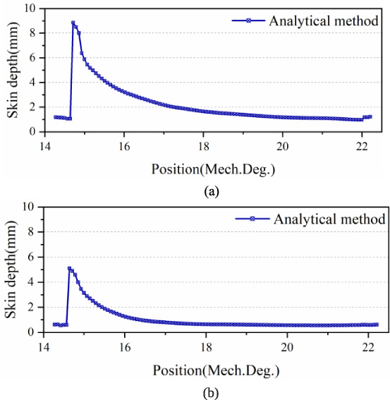
Skin depth distribution predicted analytically. (I = 100 A). (a) n =500 rpm. (b) n = 1500 rpm.
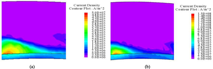
Skin depth distribution predicted by the 3-D FEM. (I = 100 A). (a) n = 500 rpm. (b) n = 1500 rpm.
Figure 18 shows the comparison of LC-ECB braking torque characteristics under different excitation currents. It can be seen that the analytical method is in good agreement with the FEM simulation results. As the speed increases, the LC-ECB braking torque increases rapidly and changes slowly after 2000 rpm. The greater the excitation, the greater the braking torque at a certain speed. The error is 6.4% at 3000 rpm.
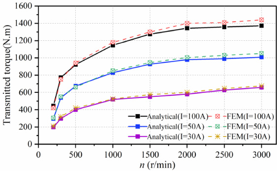
Torque characteristic for the LC-ECB.
An LC-ECB prototype was developed based on the parameters listed in Table 1. The number of turns of the excitation coil is assumed to be 100 during FEM simulation, and the number of turns is 128 during the actual processing of the prototype, so the prototype has greater excitation capacity. As shown in Fig. 19(a), the rotor and stator of the prototype could be clearly observed without the end cover. Figure 19(b) shows the LC-ECB prototype. Figure 19(c) shows the test bench, and the LC-ECB prototype was installed in the gearbox. The cooling system pumps coolant into the ECB to cool the inner surface of the stator. A torque sensor was installed between the gearbox and prime mover, and the measuring device recorded the torque in real time. The torque characteristics of the test prototype were compared to those of the proposed analytical method. During the test, the cooling system operated continuously, and the no-load torque at different speeds was measured first. The actual braking torque of the LC-ECB is the measured load torque minus the no-load torque.
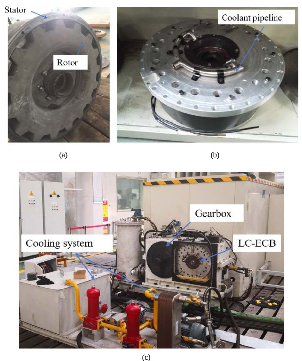
Test platform. (a) The prototype of the LC-ECB without the end cover. (b) The prototype of the LC-ECB. (c) Test bench.
The torque characteristics obtained from the test were compared to those obtained using the analytical method and FEM, as shown in Fig. 20. It can be seen that the analytical method can predict the torque characteristics of the LC-ECB. The calculation error is larger at 90 A excitation and 3000 rpm, which is 4.47%. It can be seen that the analytical calculation and FEM results are slightly higher than the experimental results. Although this paper proposes a liquid-cooled eddy current brake (LC-ECB) that effectively reduces the thermal recession of the brake, heating during brake operation is inevitable. During the prototype experiment, the braking torque data is recorded after the prototype speed stabilizes for 5 s. At this time, the prototype heats up, causing thermal recession to occur. As the experiment progresses, the phenomenon of heat recession is more obvious and the braking torque will further decrease.
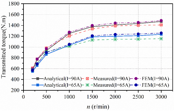
Torque characteristic for the prototype.
The distribution of the eddy current reaction magnetic field is calculated using the ampere circuital theorem, and an analytical calculation method for LC-ECB braking torque based on dynamic MEC and transient air-gap magnetic density distribution has been proposed. The static air-gap magnetic density distribution was obtained by considering the influence of magnetic flux leakage and global magnetic saturation. Considering the local magnetic saturation and skin effect, a novel double iteration algorithm is applied to obtain the transient air-gap magnetic density distribution based on the conservation principle of the magnetic pressure drop.
The availability of the analytical calculation model was verified by comparing it with the results of the 3-D FEM and prototype bench test. The analytical model does not need to solve complex partial differential equations and can easily predict the torque characteristics of the eddy current brake and transient magnetic field distribution. It takes about 10 hours to obtain a stable transient air-gap magnetic field distribution using the FEM method, while the analytical model takes less than 1 minute with the same computer configuration (CPU: Intel i7 7770; Memory: 16G). It can be easily applied to the initial design and optimization of LC-ECB. In addition, the proposed calculation method for the transient air-gap magnetic field is also applicable to eddy current couplers.
Footnotes
Acknowledgements
This study was financially supported by the Beijing Natural Science Foundation (Grant No. 3212028) and the Second Batch of Natural Science Research Fund of Hebei North University in 2022.