A model to compute the forces between small and thin co-planar magnetic disks submitted to an uniform source magnetic field is built with the help of a pseudo magnetic dipole formula, in a similar way as the one used for beads. These forces are used to compute the motion of such disks floating on the top of a viscous liquid. Numerical results are compared to experimental data: it shows a good qualitative accordance.
The direct use of magnetic force in microfluidics is relatively recent. It is currently in full development [1]. For example, a promising method to ensure a mixing function, uses small supermagnetic spheres (≈μm of diameter) that are immersed in the liquid to be mixed. When they are submitted to an uniform magnetic field, the beads form chains which are aligned with the field direction. If this field is a rotating one, the chains are set in a rotating motion. However the motion breaks the chains into small parts that rearrange themselves to form other chains. Due to the topology change, the corresponding stirring effect is particularly interesting for mixing applications [2].
There are many studies (the cited ones and others) on magnetic particles immersed in a liquid media, but those related to floating particles on its boundary are far less numerous. However this situation may be interesting; especially if it is used in a process where the magnetic particles have to be removed after having produced their mixing effect. It is easier to perform this operation if the particles are on the boundary of the liquid rather than in its bulk. Moreover, fluid mixing can also be performed with motions generated from the boundary.
Sphere-shaped particles are not really suitable as floating objects, as they have a minimum surface for a given magnetic material quantity. Thin disks are more appropriate with a surface-area-to-volume ratio from which the buoyancy of a disk is better than the one of a sphere.
However the modeling of magnetic forces exerted on the disks floating on the free surface of a fluid is a priori more difficult than for beads in the bulk, even if the disks’ motion is 2D whereas the beads’ one is 3D. It is due to the fact that the relationship between the magnetization of a disk submitted to an uniform magnetic field (directed in the plane of the disk) is not as known as the one of a sphere. And moreover, the interaction force between disk-magnets with an uniform magnetization in their planes is also not well known.
The major aim of the paper is to establish such relations, i.e. a dipole-like interaction formula for small and thin magnetic disks very close to the one used for beads as in [3].
Floating disks of soft magnetic material in a uniform source field
The Pseudo Magnetic Dipole (PMD) interaction formula
We call Pseudo Magnetic Dipole (PMD) a piece of hard magnetic material uniformly magnetized along a fixed direction which is a bounded, connected and simply-connected region. Then, if Dn is the region with its indicator function , the direction of magnetization () and mn the magnetization of the PMD, then the corresponding magnetic induction and field are the elements of the Helmholtz decomposition (𝜇0 is the vacuum permeability and we use the usual Hamilton differential operator notation ) If Dn is a sphere, then the PMD is a true dipole and , are where is the magnetic moment of the dipole. Another analytic expression can be found if Dn is an ellipsoid. However in the case of a cylinder, there is no simple analytical expression. Then and have to be computed numerically, as it would be done for more complex shapes.
The total magnetic energy of two PMDs n and n′ is The necessary condition for to be the minimizing argument is Due to the orthogonality between the rotational-free and divergence-free space vector fields, this condition reduces to which are exactly the magnetic equations that should be stated directly superposing (1) for n and n′. The minimizing argument of (3) can be written as where and are the dimensionless fields solution of the dimensionless Helmholtz decomposition (1) The PMDs interaction part in Wnn′ is And due to the preceding orthogonality, Vnn′ can also be expressed in terms of magnetic moments , and mean fields as the reciprocal relations
The floating disks case
The two considered PMDs are disks that float on a flat surface (plane ) of a liquid normal to the direction , their centers of gravity are and in the plane . The direction of magnetization is also assumed to be in the plane . Then their interaction energy (9) can be expressed as where 𝛼 and 𝛽 are dependant variables of the distance between the centers ().
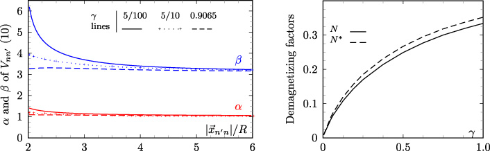
If the floating objects were spheres then 𝛼 = 1 and 𝛽 = 3 for any radius. For disks of radius R and thickness e, 𝛼 and 𝛽 really depend on the distance and also on the ratio 𝛾 = e∕2R.
Briefly, using the effective computation of 𝛼 and 𝛽 requires two numerical computations of for the aligned cases () and normal case (); and integrations of this field on the regions Dn′ for several distances . Practically, as outside of the region Dn, we have computed the corresponding scalar potential of with an adapted Biot and Savart formula.
Figure 1(left) shows this dependence for three different ratios 𝛾 = e∕2R. For small values of 𝛾 (below 0.05), which is the considered case here, 𝛼 and 𝛽 do not depend on the ratio e∕2R. When 𝛾 = 0.9065, i.e. the ratio known for that a cylinder is almost equivalent to a sphere (see [4], p. 3611) 𝛼 and 𝛽 have almost the same constant values as the ones of the sphere.
The equivalent interaction energy formulae (9) and (10) allow to express the force and the mean field on the PMD n’ due to the PMD n as where denotes the gradient with respect to the vector .
On left: 𝛼 (red) and 𝛽 (blue) of the interaction energy Vnn′ (10) for two cylinders versus the distance between cylinder centers for different 𝛾 = thickness/diameter. On right: proposed demagnetising factor N and magnetometric one N∗ in [4].
The induced moment in a floating disk of soft magnetic material
The induced magnetic induction in a region Dn made of a soft magnetic material (relative permeability 𝜇r) and submitted to an uniform source magnetic field is the minimizing argument of As well as the (1) to (5) derivation, mutatis mutandis the necessary condition leads to which is the magnetic system that can be derived directly from the Maxwell equations.
Instead of using this formulation to compute , we use the space in which is searched as the two dimensional space (mn and the angle between and for example) where . Then the minimizing problem (12) reduces to Some computations and reordering lead to In a general case the induced magnetization mn depends on the direction of the source magnetic field and may be expressed as a symmetric tensor. But we are here only interested by the floating disk case where the direction is on the plane (); so the tensor reduces to a scalar N and then mn does not depend on . N is an intermediate result that can be called a demagnetizing factor. It is not the magnetometric demagnetizing factorN∗ defined in [4], which is rather defined as . However quantitatively the difference between N and N∗ is low (see Fig. 1, right), especially when the ratio 𝛾 is low. In this case an asymptotic analysis shows that N ≈ N∗≈ 𝛾 (0.230 −0.324log(𝛾)). Then whatever is 𝜇r (infinity included) the limit for e = 0 of the magnetic moment Mn is zero.
The interaction energy of many floating disk of soft magnetic material
We consider now the identical floating disks case with Nb axisymmetric pieces of soft magnetic material labelled n for n =1…Nb. The interaction energy is where each magnetic moment is found by considering the disk n as submitted to an uniform field which is the sum of the source magnetic field and the mean magnetic fields (11) due to the other magnetic moments. Then the equations (15) can be gathered as which is is a vectorial equation of the Nb vectors . By varying n, we obtain a system that allows to find the Mn. In fine, in accordance to (11) the force exerted on the disk n is
Experiment, simulation and comparison
We use 4 steel thin disks (relative density ≈ 8), which radius and thickness are R =1 mm and e = 20 μm and then mass ; they are assumed to have a high permeability, which is estimated as 𝜇r = 1000. The disks are put on the top of a glycerol solution (measured viscosity 0.45 Pa s, relative density ≈ 1.2); and the surface tension is high enough so that they well float (see Fig. 2). The solution with disks on its top is put inside an electric motor stator, whom the windings are connected in a 2-pole configuration and fed by a 3-phase source of adjustable tensions and low frequencies1; they are chosen to produce an almost uniform rotating field with a frequency of 0.1 Hz and an intensity of hs = 4400 A∕m.
The motion of disks is captured with a basic 30 fps camera. Figure 2 (bottom line) shows a sample of the recorded images: the two right disks attract and touch each other after 1.5 s; they rotate and there is a contact with the left bottom disk after 3 s; after the three disks turn half a revolution, there is a contact with the last disk; and finally the four disks form a chain that rotates synchronously with the source magnetic field.
Sequence of disks motions. Bottom : experiment; top : model, the arrow on the bottom left represents the direction of the rotating source magnetic field ; the arrow in each disk represents its the magnetic moment.
For the simulation, the centers of the 4 disks (2 × Nb degrees of freedom) are time dependent and solutions of (Newton notation for time derivative) where 𝜂 is the drag coefficient obtained by the computation of the fluid flow generated by the motion of a single disk on the top of the liquid with the model decribed in [5]; we obtain 𝜂 = 0. 8 mNs/m. The inertia force is canceled because the time ms while the characteristic time is 1 s. is computed with (18) and depends only on the and which is a uniform rotating field. The are a system of forces, which are the Lagrange multipliers of the impenetrability constraints on the disks that are in contact when the forces between them are attractive.
An Euler semi-explicit (with iterations to actualize the ) integration of the first order equation (19) with a time step 10/3 ms is used (10 computations between each image to obtain a 30 fps sequence). The raw results are shown Fig. 2 (top line), the same comments as the ones for the experiment can be done.
Conclusion
The Pseudo Magnetic Dipole interaction (10) and the demagnetizing factor (15) formulae are strong enough to be used in a simulation, which is qualitatively in a good agreement with experiment. There is however a gap. Rather than other causes, this gap is probably due to the poor used fluid flow modeling. In fact, as reported in [3] (for the case of beads), the interaction between the velocity fields generated by the motion of each disk is not negligible. But fortunately they should be taken into account with approximations similar to those made for the electromagnetic force, which is however another work.
Footnotes
1
A laboratory (LEMTA) device designed by A. Delconte and M. Marchand.
References
1.
PammeN., Magnetism and microfluidics, Lab on a Chip6(1) (2006), 24–38.
2.
KangT.G.HulsanM.A.AndersonP.D., Chaotic mixing induced by a magnetic chain in a rotating magnetic field, Physical Review E76(6) (2007), 066303.
3.
OduwoleO.GrobD.T. and SheardS., Comparison between simulation and experimentally observed interactions between two magnetic beads in a fluidic system, Journal of Magnetism and Magnetic Materials407(2016) 8–12.
4.
ChenD.-X.BrugA. and GoldfarbR.B., Demagnetizing factor for cylinder, IEEE Trans. on Mag.27(4) (1991), 3601–3619.
5.
DufourS.VinsardG. and SaatdjianE., Motion of a conducting floating object on top of an electrolyte submitted to Lorentz forces, IEEE Trans. on Mag.51(3) (2015), 1–4.