
Abstract
Based on the equivalent magnetic dipole theory, a method for designing gradient coils of the Halbach magnet is proposed. Minimizing the energy consumption of the gradient coil is set as the optimal object, and the variance between the calculated and expected magnetic fields is taken as the penalty function. In this way, a quadratic optimization problem that cannot easily satisfy the magnetic field constraint condition can be easily transformed into an unconstrained optimization problem. By using the lsqnonlin optimization toolbox of Matlab, the distribution of the stream function on the cylindrical surface is calculated, and the three gradient coils of the Halbach magnet are obtained according to the contour of the stream function. To validate the designed coils, the Biot-Savart law is applied to calculate the distribution of the magnetic field. The results show that the magnetic field distribution agrees well with the design object. The gradient coils are fabricated and the magnetic field distributions in the region of interest are measured. The measured data are almost similar with the calculated data, and the measured gradient uniformity of
Introduction
The Halbach magnet [1] performs well without an iron yoke and has the characteristics of a strong magnetic field, low weight, and small size. The magnetic field at the center of the magnet is homogeneous and has a low fabrication cost. Therefore, the Halbach magnet is an ideal portable NMR (nuclear magnetic resonance) device for analysis and imaging as well as presents a popular research direction in online NMR spectroscopy and imaging [2, 3, 4]. In this paper, the application of the equivalent magnetic dipole method for designing gradient coils is studied, and these coils will be used for the Halbach magnet with a special structure (i.e., the main magnetic field is in a radial direction and the gradient coils are placed on the cylindrical surface).
The design of gradient coils is an inverse problem of the electromagnetic field. These coils can be divided into discrete and distributed windings [5]. When discrete windings are designed, the shapes are pre-determined and the position and angle of the windings on the frame are adjusted to meet the given design object using certain algorithms, such as the conjugate gradient descent algorithm [6], simulated annealing algorithm [7, 8], neural network algorithm [9], and fuzzy membership functions algorithm [10]. Meanwhile, when distributed windings are designed, the shapes of the windings are not predefined, the desired magnetic field distribution in the region of interest (ROI) is known and set as a goal, and the structure of gradient coils can be obtained by reverse calculation. Moreover, this method, which shows better performance in designing coils [11], is easily constrained by inductor, energy consumption, and self-shielding conditions. The detailed solution methods include the matrix inversion method [12, 13], the stream function method [14, 15], the target field method [16], the harmonic coefficient method [17], and the equivalent magnetic dipole method (it is similar with the boundary element method) [18, 19]. Each magnet structure has a slightly difference of design method.
Given the radial main field direction of the Halbach magnet, the required magnetic field of the gradient coil differs from the field distribution of the conventional superconducting MRI and the C-type permanent magnet. Moreover, the coil needs to be distributed on a cylindrical surface. However, the above methods are only useful for magnets with an axial main field direction and for coils that are distributed on a flat surface. Meanwhile, the methods for designing gradient coils for the Halbach magnet are only limited to the equivalent magnetic dipole method [19] and the harmonic coefficient method [3]. The equivalent magnetic dipole method has been used by Lopez et al. to design shim coils for superconducting MRI and planar permanent magnets as well [20].
Structure of the Halbach magnet. (A) 3D structure of the Halbach magnet. The gradient coils are distributed on a white plastic cylinder with a 75 mm diameter inside the Halbach magnet. The magnet is composed of three discrete Halbach rings with a radius of 125 mm and a gap of 12 mm. A single ring consists of 24 magnetic bars, and its main field is placed along the 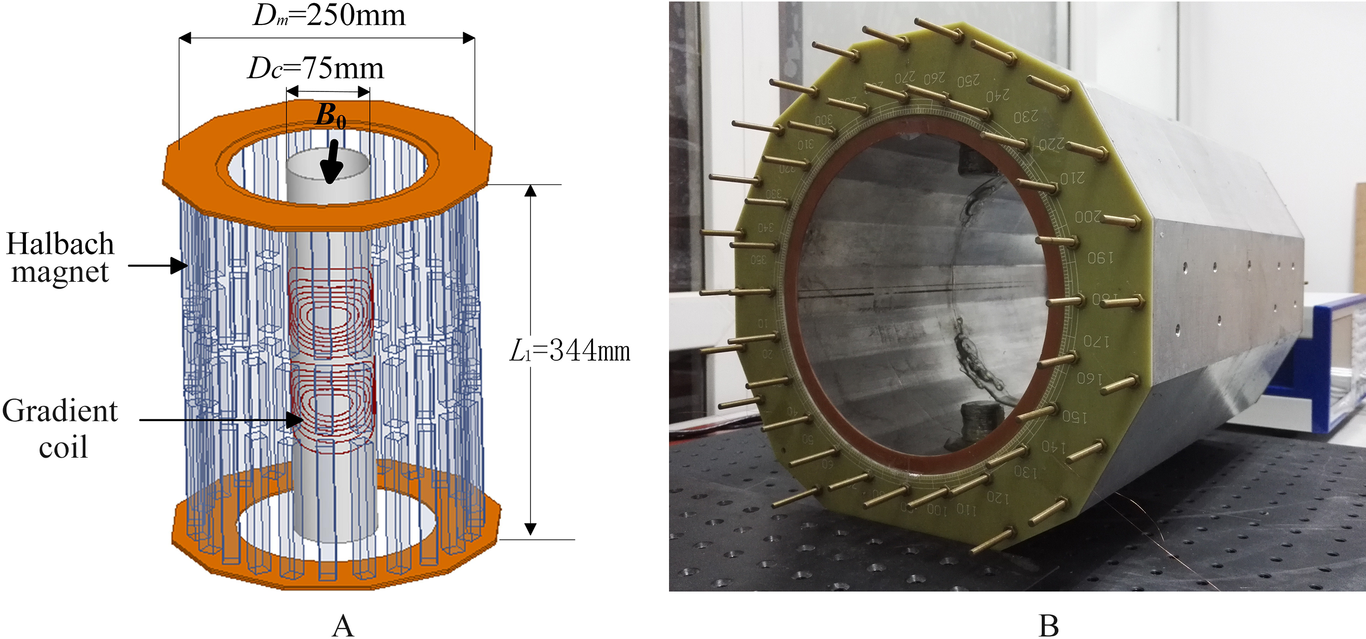
The gradient coils in this paper are designed based on the Halbach magnet shown in Fig. 1. This magnet is fabricated for measuring core porosity, and its main field lies along the
The gradient coil with the current can be treated as a number of current-carrying loops, which in turn can be regarded as magnetic dipoles when one loop is much too small for the area where the coil is located. As shown in Fig. 2, each rectangular arc block on the cylindrical wiring surface is supposed to be a magnetic dipole. Therefore, the magnetic field in the ROI is generated by these dipoles. The core question in this paper is how to derive the structures of gradient coils according to the given magnetic field of gradient distribution.
Structure of the meshed cylindrical surface of coils. The surface is discretized to 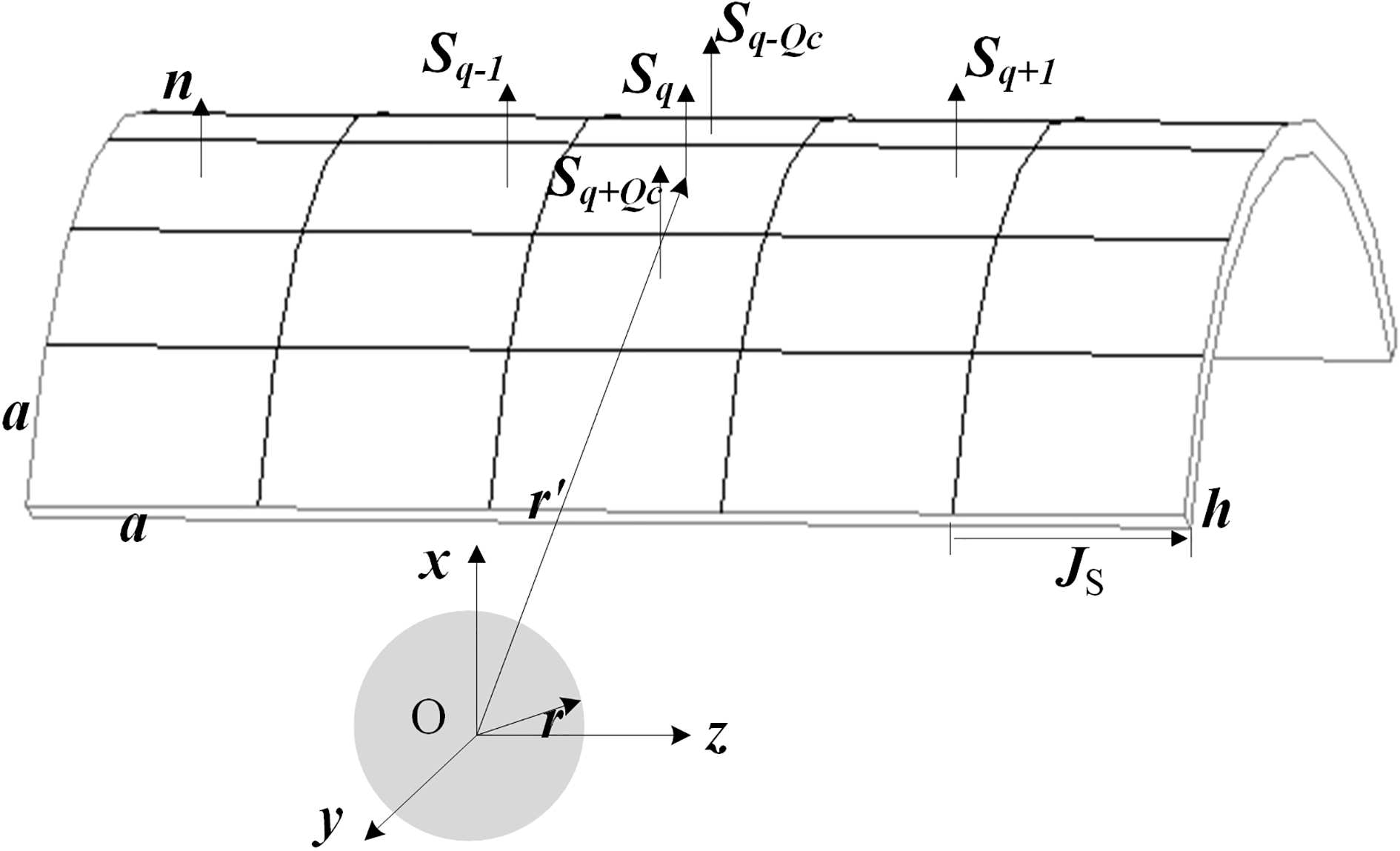
The magnetization of the single dipole is denoted as
The relation of current density
where
Therefore, we can write
The structure of the gradient coil can be directly obtained from the contour lines of stream function
The cylindrical surface where the gradient coil is located is divided into
If
Equation (2) shows that the current distribution can be obtained by calculating the
By substituting Eq. (4) into Eq. (5), we can obtain the magnetic field expression of field point (
where
and
If the design object only contains the gradient of the magnetic field distribution, then the structure of the coils may become too complicated and rough, which has problems of fabricating difficultly and high temperature with current, Therefore, the energy consumption must be minimized to obtain one optimal object.
The total energy consumption can be expressed as
In other words, if the energy
According to the quadratic programming problem, the initial solution that satisfies the above constraints cannot be easily obtained, thereby interrupting the solution process. Therefore, the constraint problem can be transformed into an unconstrained optimization problem by constructing penalty function. The magnetic field constraint is taken as a penalty function multiplied by the penalty parameter
where the latter term denotes the sum of squares of the difference between the magnetic field
To solve the optimization problem such as that in Eq. (11), the lsqnonlin toolbox of Matlab is used. This toolbox solves the nonlinear function of Eq. (12) as follows by using the least squares method
where
After solving the optimal values of
The penalty parameter
Structures and magnetic field distributions of the 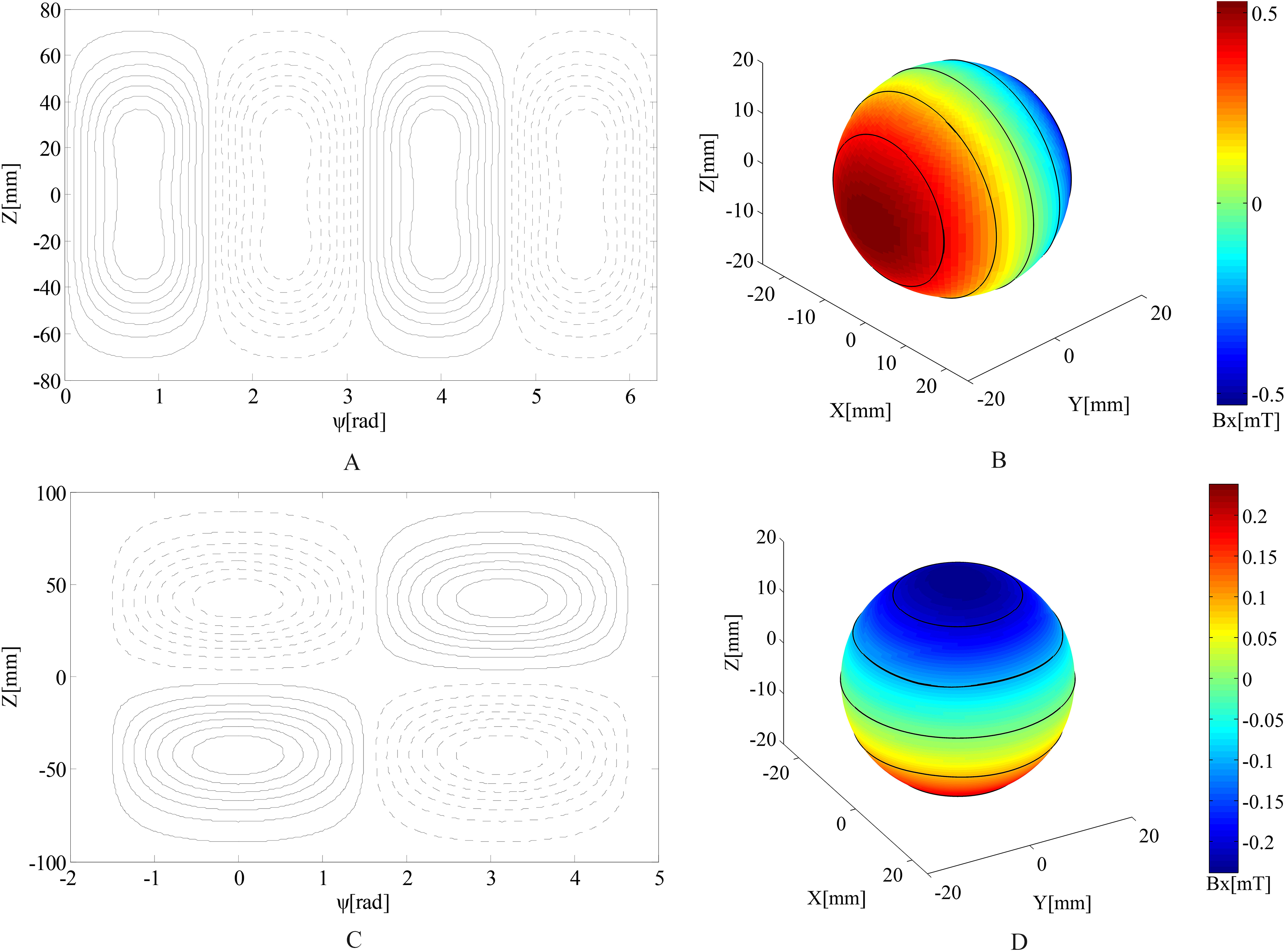
When calculating
The designed gradient coils are located on a cylinder with a radius of 37.5 mm and length of 235 mm. This cylinder is subdivided into 2500 elements, and the ROI is a sphere with a 20 mm radius and 100 target points. Using the above method, the structures of the
In the actual design, parameter
Performance parameters of the calculated and measured of gradient coils
Performance parameters of the calculated and measured of gradient coils
(A) The PCB board of the 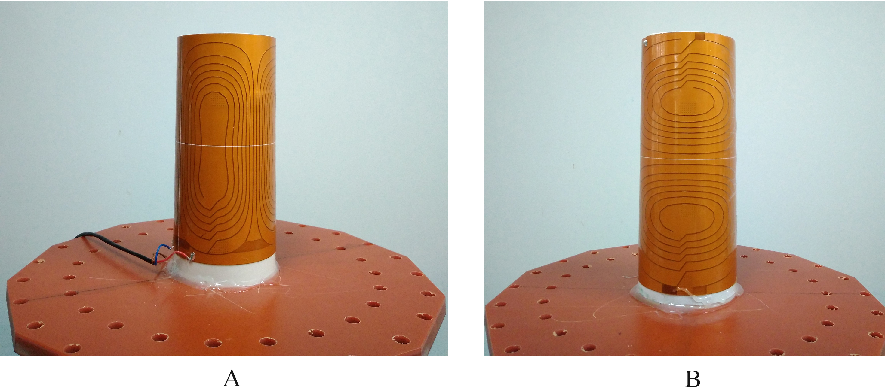
System for measuring the magnetic field distributions of gradient coils.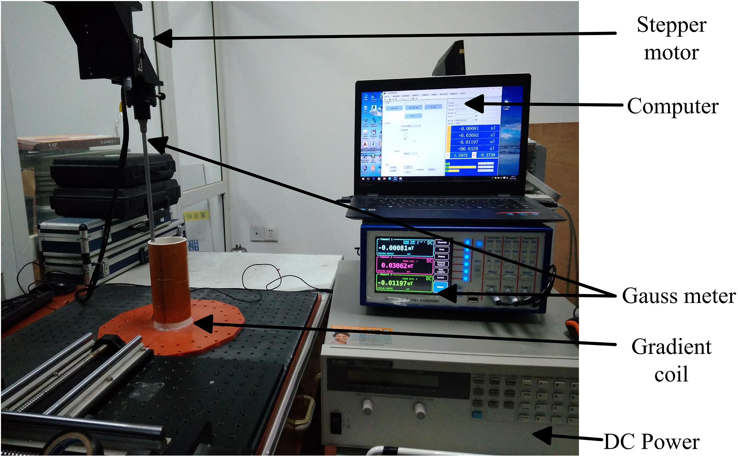
The distributions of the magnetic field of the coils in the ROI are verified by applying the Biot-Savart law, and the
A flexible PCB board made of copper foil pasted on the substrate film and covered with an insulating layer is flexible, thin and easily processed. The above designed gradient coils are realized by using flexible PCB boards, and in this way the fabricated coils can be easily wound on a hollow plastic cylinder with a 75 mm diameter. The
Using the FW.Bell8030 Gauss Meter made in the US, we measure the magnetic field distribution of
Diagrams of the magnetic field distributions along the axial planes of 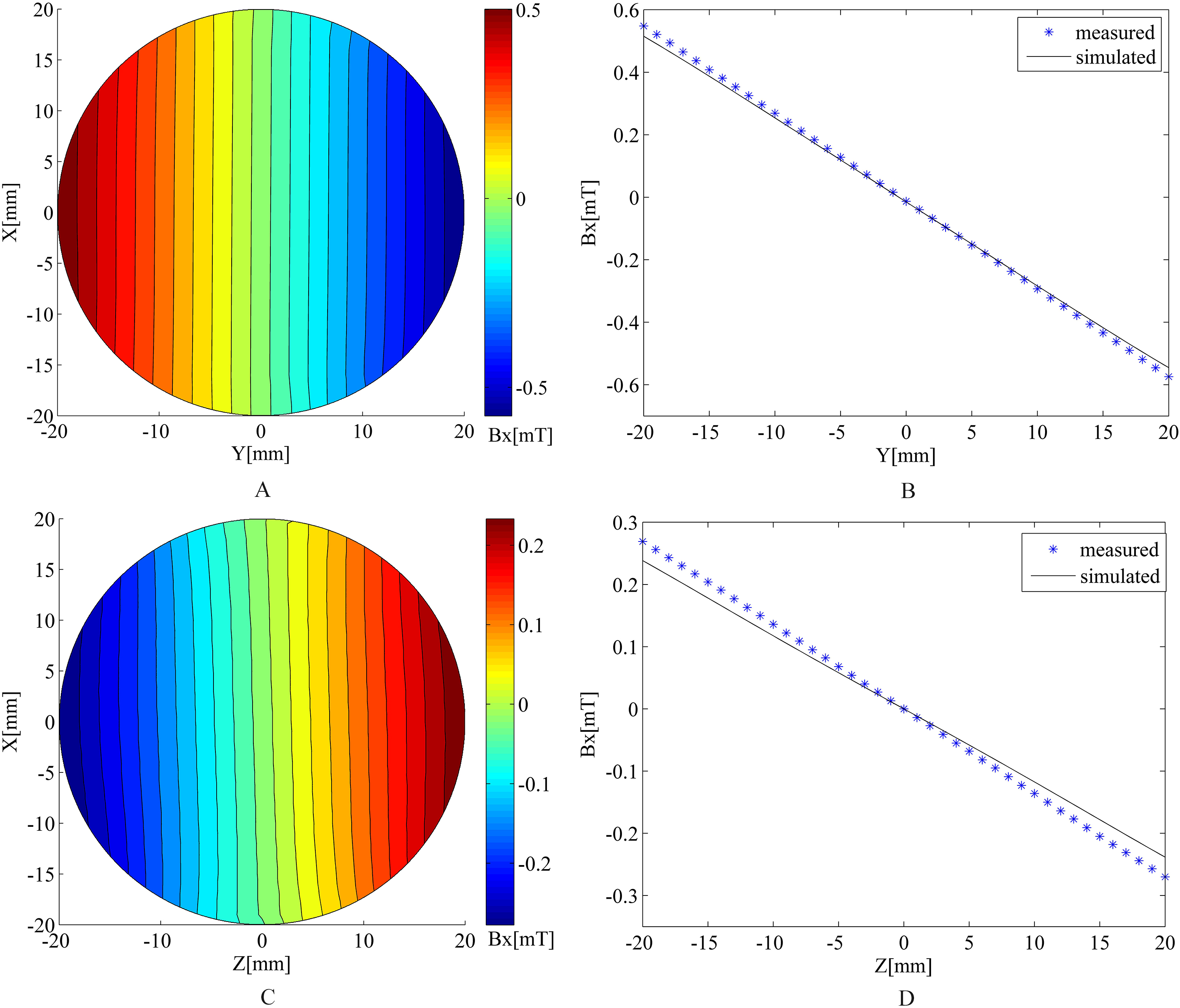
As can be seen in Fig. 6, the measured magnetic field distributions are almost similar to the calculated ones. Therefore, the fabricated coils meet the design requirements. The calculated and measured performance parameters of the coils are shown in Table 1. The measured gradients of the
The magnetic field distributions of fabricated PCB coils are worse than those of designed coils because while drawing PCB board coils, the structure of the spiral plane is used to make sure that the current in the coil flows smoothly, thereby leading to the unavoidable asymmetry of coils. When the PCB boards are wound on the cylinder, a fabrication error may take place. However, the difference in the magnetic filed distributions of the measured and calculated gradients are within the acceptable error.
Given that the main magnetic field of the Halbach magnet lies along the radial direction, the methods for designing a gradient coil for superconducting nuclear magnetic resonance cannot be directly used. Therefore, based on the equivalent magnetic dipole method, energy consumption is proposed as the optimization object, and the quadratic problem with the magnetic field constraint is transformed into an unconstrained optimization problem that uses the difference between the calculated and expected magnetic fields as a penalty function. The lsqnonlin optimization toolbox of Matlab is used to solve the stream function that is distributed on the cylindrical coil. The structures of the gradient coils are then obtained by applying the contouring stream function. The proposed method is simple, efficient, general, and can be used for designing high-order shim coils for nuclear magnetic resonance.
Footnotes
Acknowledgments
This work was supported by the National Natural Science Foundation of China (No. 51677008, 51377182, 51707028 and 11647098) and the Fundamental Research Funds for the Central Universities (106112017CDJQJ158834).