
Abstract
This paper presents a dual-rotor permanent magnet synchronous reluctance machine (PM-SynRM) with toroidal windings to improve the magnetic torque and the utilization of two torque components, thus to obtain high electromagnetic performance, such as torque, efficiency, and power factor. To highlight the advantages of the proposed dual-rotor PM-SynRM, all of its machine characteristics, including airgap flux density, back electromotive force (EMF), torque, power, efficiency, and flux weakening capability are compared to those of a conventional PM assisted SynRM (PMA-SynRM) with the same machine size and operating conditions, with the aid of a finite element method (FEM) using the JMAG-Designer. Furthermore, the proposed dual-rotor PM-SynRM is verified to have superior endurance against the magnet irreversible demagnetization within five times of the rated current excitation.
Keywords
Introduction
Permanent magnet (PM) machines have been actively investigated for various applications owing to their high torque density and efficiency [1–3]. Most of up-to-date PM machines utilize the rare earth magnet materials because of their high remanence and coercivity values [4]. However, the recent volatility of rare earth PM price leads to a critical challenge in those applications where a high quantity of PMs and mass production are required [5]. Therefore, the development of high-performance electrical machines with less or zero rare earth PMs is greatly desired.
The synchronous reluctance machine (SynRM) is regarded as one of the viable alternatives featuring robust structure and low cost without using PMs, but it sacrifices torque density, efficiency, and power factor compared to the PM machines [6–8]. To improve the performance, the rotor flux barriers of the SynRM can be inserted with proper amounts of PMs, which create a new PM-assisted SynRM (PMA-SynRM). In particular, the PMA-SynRM with ferrite magnets are more attractive due to their low cost, high torque density, and wide speed ranges [9–12]. However, it was also found that the PMA-SynRMs exhibit some disadvantages. The magnetic torque and the reluctance torque of the PMA-SynRM jointly contribute to the total torque where their maximum values meet at different current phase angles displaced theoretically by 45° [13]. Therefore, the two torque components can’t be fully utilized to contribute to the total torque. Furthermore, the PMA-SynRM produces weak magnetic airgap flux density with high harmonic distortions, resulting in a low magnetic torque with high torque ripple. Nevertheless, the situation can be improved by the design concept with axially integrated two rotors in [14], in which the maximum values of the magnetic and reluctance torques can meet at the same current phase angle, thus to improve the performance, but suffers a big degradation of reluctance torque and unbalanced axial electromagnetic force. In [15], the machine with radially integrated two rotors is briefly depicted, and in [16], the same machine structure is presented and studied for traction application, whereas the work mostly focused on the analysis of resultant torque improvement and its effects, rather than a more direct study on the analysis of torque components.
In this paper, a dual-rotor PM synchronous reluctance machine (PM-SynRM) with toroidal windings is proposed to obtain high machine performance, including torque, efficiency, and power factor, by focusing on the study of improving the magnetic torque and the utilization of two torque components.
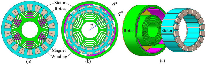
Topologies of machine models. (a) Referenced model. (b) Proposed model. (c) 3-D structure of the proposed model.
To highlight the advantages of the proposed dual-rotor PM-SynRM, all of its machine characteristics are compared to a conventional PMA-SynRM with the same machine size and magnet amounts under the same operating conditions, with the aid of a finite element method (FEM) using JMAG-Designer.
Machine topologies and specifications
The machine topologies are shown in Fig. 1. To highlight the contribution of the proposed machine, the conventional PMA-SynRM is adopted for comparison, nominated as the referenced model as shown in Fig. 1(a). The referenced model exhibits 6 magnet poles and 18 stator slots, and the low-cost ferrite PMs are inserted in a central position within the rotor flux barriers. The proposed dual-rotor PM-SynRM keeps the same pole and slot combination as shown in Fig. 1(b). The toroidal windings are wound on the stator yoke to improve the working surfaces of the stator core and the slot fill factor. The two rotors of the proposed model, integrated by a SynRM and a surface-mounted PM machine (SPMM), are jointed for one shaft output. Figure 1(c) shows the 3-dimentional structure of the proposed model, while the two rotors are connected by one end disc working as a cooling blower. It is worthy to mention that the referenced and proposed models keep the same machine size, materials, magnet amounts, and winding turns. The main machine specifications are shown in Table 1.
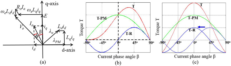
Design principle [14]. (a) Vector diagram. (b) Torques of the referenced model. (c) Torques of the proposed model.
The main machine specifications
In the referenced model, the rotor shape maintains circumferential symmetry such that the d-axis and q-axis for each rotor pole can be defined. By convention, the rotor symmetry allows to develop the d–q rotor frame equivalent circuit using the Park Transformation, and the corresponding vector diagram of the circuit is illustrated in Fig. 2(a). Thus, the electromagnetic torque can be derived as
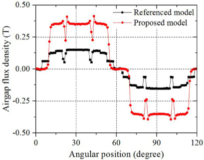
Airgap flux density.
In the proposed model, the superposition mechanisms of the torque components are changed by designing the assembling configurations of the SynRM and SPMM. As shown in Fig. 1(b), the d
∗ axis is defined as the central line the PM pole of the SPMM, and the q
∗ axis is defined as the central line of the saliency pole of the SynRM. The displacement angle between the two axes can be determined through an iterative process using the FEM to make the magnetic torque and reluctance torque reach their maximum values nearly at the same current phase angle, which is expressed as
To reveal the contribution of the proposed model, the frozen permeability method (FPM) is utilized to provide visible insights into the separation of the magnetic torque and the reluctance torque [17]. The total torque is obtained with all excitations of the PMs and stator currents. And the reluctance torque is obtained by removing the PMs. The magnetic torque is finally obtained by subtracting the reluctance torque from the total torque. The target torque characteristics of the proposed model can be illustrated as shown in Fig. 2(c).
Airgap flux density, back EMF, and magnetic flux density distribution
The machine characteristics at the no-load conditions are first predicted by the 2-D FEM using the JMAG-Designer. The airgap flux densities of the referenced and proposed models are compared in Fig. 3. It shows that the proposed model with the surface-mounted PMs can produce much higher airgap flux density than the referenced model with the same PMs inserted in the rotor flux barriers. Therefore, the proposed model produces higher back EMF in phase than the referenced model as illustrated in Fig. 4. The RMS value of back EMF in the proposed model is 3 times of that of the referenced model. The performance at the load conditions are simulated by feeding the stator windings with sinusoidal current excitations of 4 Arms/mm2. Figure 5 shows the comparison of the magnetic flux density distribution. It shows that the magnetic flux density of the proposed model exhibits a maximum value of 1.5 T, which is stronger than that of the referenced model. Furthermore, the proposed model releases the saturation condition in the inner rotor ribs when compared to the referenced model.
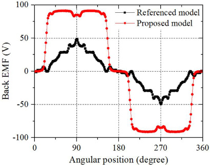
Back EMF in phase.

Magnetic flux density distribution. (a) Referenced model. (b) Proposed model.
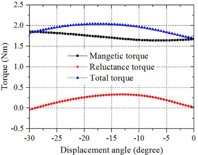
Torques with respect to the displacement angle of the proposed model.
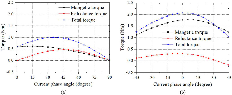
Comparison of torque characteristics. (a) Referenced model. (b) Proposed model.
The torques with respect to the displacement angle of the proposed model is shown in Fig. 6. Theoretically the displacement angle will be 15° to make the magnetic torque and reluctance torque reach their maximum values at the same current phase angle. However, due to the effects of leakage flux and local saturation during the flux transmission process, the total torque will not be the maximum even though the maximum values of the two torque components meet at the same current phase angle. Through an iterative process using the FEM, the maximum total torque of the proposed model is obtained when the displacement angle is 17.25°, while the two torque components get their maximum values near the same current phase angle.
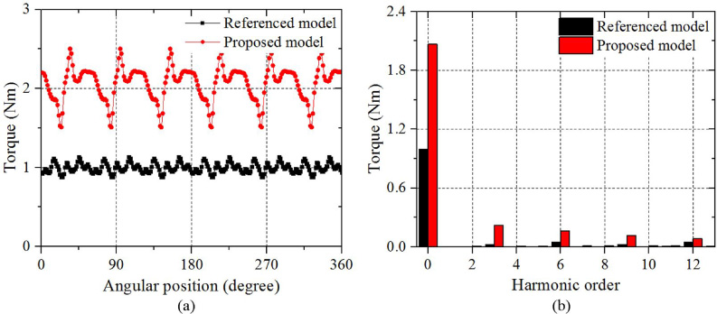
Comparison of torques. (a) Electromagnetic torques. (b) FFT of electromagnetic torques.
Comparison of the analysis results by the 2-D FEM
a/b*: a represents the utilized torque components, b represents the maximum torque components.
Figure 7 compares the torque characteristics of the referenced model and proposed model with respect to current phase angles. It shows that the two torque components of the basic model reach their maximum values at different current phase angles by 45°, as shown in Fig. 7(a). In contrast, the two torque components of the proposed model reach the maximum values near the same current phase angle by 5° apart from each other, which greatly improves the total torque as shown in Fig. 7(b). The comparison of electromagnetic torques at the maximum torque condition is shown in Fig. 8(a), and the corresponding fast Fourier Transform (FFT) analysis is shown in Fig. 8(b). The results show that the torque of the proposed model are significantly increased by more than 2 times when compared to that of the referenced model, despite that the proposed model contains higher torque ripple (peak-to-peak torque value versus the average torque value) than the referenced model, as listed in Table 2.
The outer power of the proposed model is increased with the increase of the torque. At the same operating condition with the same current density, the efficiency and power factor of the proposed model are highly increased by 7.9% and 11.8%, respectively, when compared to those of the referenced model, as listed in Table 2. If the proposed model is operated at the same power point as the referenced model, the current excitation can be reduced for a greatly reduced copper loss. Consequently, the efficiency is increased by 9.5%, and the power factor is increased by 12.9%, when compared to the referenced model, as shown in Table 3. Alternatively, the machine size and material usage of the proposed model can be reduced for the same power grade as the referenced model, with a predictably improved torque density and efficiency. It is worthy to note that the efficiencies are herein estimated by the ratio of the output power to the sum of the output power and losses, while the losses are composed of the calculated copper loss and the simulated hysteresis loss and eddy current loss [18].
Comparison of the analysis results at the same power point
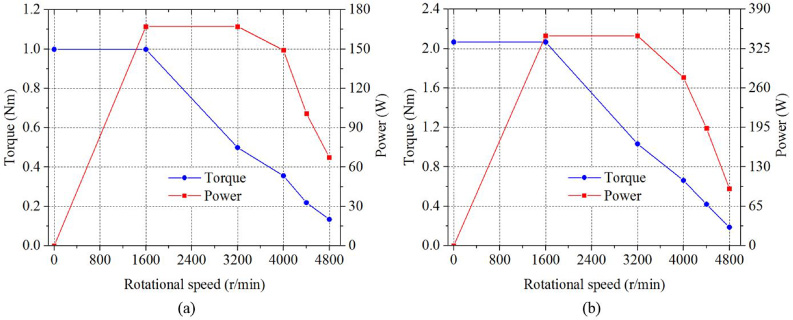
Comparison of flux wakening capability. (a) Referenced model. (b) Proposed model.
Due to the design configuration of two rotors, the PM flux linkage of the proposed model is highly increased when compared to the referenced model, which will limit the speed range as well as the flux weakening capability with the same DC voltage. To provide a fair comparison for the flux weakening capability, the maximum voltages of two machine models are herein determined based on their rated performance with the same current density, thereby the referenced and proposed models are simulated with the maximum DC voltages by 125 V and 220 V, respectively. Figure 9 compares the characteristics of torque and power with respect to speed ranges. The results show that the proposed model exhibits the similar flux weakening capability as the referenced model. It is worthy to note that speed range of the referenced model is not designed to be superior since it is originally designed for a fan application.

Demagnetization analysis of the proposed model.
The surface-mounted ferrite magnets of the proposed model is more easily affected by the armature reaction, leading to magnet demagnetization. To assure the design reliability, the analysis of magnet demagnetization, reflected by a ratio in (3), is performed within five times of the rated current.
The analysis result of demagnetization ratios of the proposed model is depicted in Fig. 10. It shows that the demagnetization ratios are nearly zero within five times of the rated current, owing to the design of sufficient magnet thickness with a low rated current density (4 Arms/mm2). Therefore, the result indicates that the proposed model has superior endurance against the magnet demagnetization.
This paper has presented a high-performance dual-rotor PM-SynRM with toroidal windings and special configuration of two rotors. Based on the analysis results by the FEM, it demonstrated that the proposed PM-SynRM exhibits highly improved torque, power factor, efficiency, and similar flux weakening capability as compared to the conventional PMA-SynRM with the same machine size and magnet amounts. Furthermore, the proposed dual-rotor PM-SynRM was verified to have superior endurance against the magnet irreversible demagnetization within five times of rated current excitation.
Footnotes
Acknowledgements
This work was supported in part by the National Natural Science Foundation of China, under Grant 51707107 and 51577107, in part by the fundamental research funds of Shandong University, China, under Grant 2016TB013, and in part by the project funded by the China Postdoctoral Science Foundation, under Grant 2017M612269 and 2018T110688.