
Abstract
Recently, the majority of artificial hearts have been non-pulsatile types. However natural hearts are pulsatile, and the long-term bio-compatibility of the non-pulsatile types has not been confirmed. We developed a linear actuator that can expect to be applied to pulsatile artificial heart. This linear actuator was applied to an electromagnetic pump. It consists of power transmission, tanks, and permanent magnets. We propose a structure to reduce power consumption by a spring. Reduction in power consumption makes possible to downsize the entire apparatus.
Introduction
Recent medical technology is progressing day by day. However, reliable life-saving for extremely complicated cardiac malformations and serious myocarditis has not been realized. Artificial hearts and heart transplants are the ones that substitute for such hearts which are difficult to treat. The artificial hearts have a pulsatile type in which blood is delivered by expanding and contracting the volume of a tank portion, and a non-pulsatile type in which constant flow is maintained. Non-pulsatile type with axial flow pumps and centrifugal pumps, which is a non-volumetric type with a compact structure that most of the artificial hearts currently being studied can be embedded in the body, has become mainstream [1,2]. However, in the non-pulsatile type, there is a disadvantage that a sucking phenomenon that blood ejection is hindered is liable to occur. Also, the biocompatibility of long-term in a non-pulsatile circulation has not been confirmed.
The electromagnetic pump developed.
Murakami et al have developed pulsating electromagnetic pumps using permanent magnet linear actuator with the aim of application to artificial hearts [3]. Since the electromagnetic pump performs expansion and contraction of the tank with the force of attraction and repulsion of the permanent magnet, a large force of the permanent magnets can be taken out with small energy for rotating the motor that drives the actuator. In this point, application to embedded artificial heart can be expected. The electromagnetic pump is intended for application to an implantable artificial heart. Therefore, downsizing of the whole device and reduction of power consumption are problems to be solved. The developed linear actuator uses a single-sided multipole magnet. As one of the facing magnets is rotated by the motor, it repeatedly attracts and repulses the other magnet. It is a mechanism that performs a linear motion by increasing or decreasing the distance between the magnets. However, the rotation torque for rotating the magnet in the completely attracted state is large, and a high output motor is required. As a result, there is a problem that the entire apparatus becomes large. In order to solve these problems, we propose a mechanism for accumulating torque energy in a spring attached to a rotating magnet by reciprocating the rotating magnet between a completely attracted state and a repulsive state. Therefore, the rotational torque is compensated by the restoring force of the spring. As a result, it is possible to reduce the rotation torque of the magnet and use a small motor. Therefore, reduction in size of the entire apparatus is expected. It is also expected to reduce power consumption. In this research, we develop linear actuator with features suitable for artificial hearts with such advantages. In addition, as a preliminary step to the application to the artificial heart, we applied it to the electromagnetic pump and decided to evaluate the basic structure and characteristics of the experiment.
Structure of the electromagnetic pump
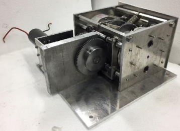
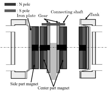
Figure 1 shows the pulsating electromagnetic pumps developed using permanent magnet linear actuator. Figure 2 shows 3D-CAD model of the electromagnetic pump. The electromagnetic pump newly developed in this research is mainly composed of permanent magnet, tank, driving part. The drive uses a DC motor, and the reduction ratio between the motor and the permanent magnet is 1:180. We use 4 poles, 6 poles, 8 poles for permanent magnets. Each magnet reciprocates 90 degrees for 4 poles, 60 degrees for 6 poles and 45 degrees for 8 poles. The electromagnetic pump performs one beat by reciprocating the magnets once. As a result, the maximum beat frequency of the linear motion part calculated from the maximum rotation speed of the motor is 2.56 to 5.14 Hz. The specifications of the electromagnetic pump are shown in Table 1.
Permanent magnet
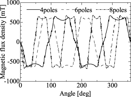
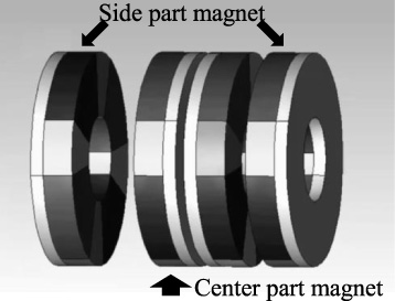
Figure 3 shows the magnetic flux density for each magnet angle at 0.5 mm from the magnet surface. Figure 4 shows an annular magnet row using halbach array with 4 poles. Magnet rows using Halbach arrays are formed by using segment magnets of 30°, 15° for single-sided 8-pole magnets, 40°, 20° for single-sided 6-pole magnets and 60°, 30° for single-sided 4-pole magnets. The magnets with a large angle are magnetized in the thickness direction. The small magnets are magnetized in the circumferential direction. The white arrows are magnetization direction in Fig. 4. It is formed by assembling magnets magnetized in the thickness direction between magnets magnetized in the circumferential direction. This increases the magnetic flux density on one side and the extent of the magnetic flux. We construct an actuator by using this four rows of magnets.
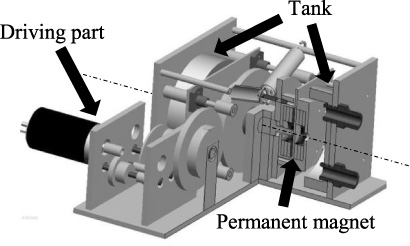
3D-CAD model of the electromagnetic.
The magnetic flux density for each magnet.
Specifications of the electromagnetic pump
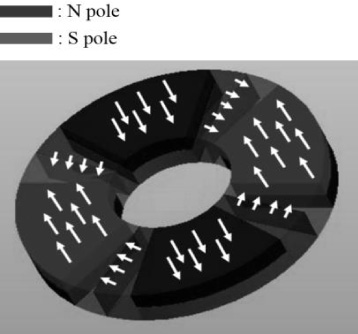
An annular magnet row using halbach array (4poles).
Figure 5 shows a layout view seen from the side. The actuator is constructed using four sets of annular magnet rows. The four sets of annular magnet rows are coaxial. The central two rows of magnets only perform rotational motion and are connected by a shaft so that rotation is synchronized. The side magnets at both ends are restricted to move only in the horizontal direction while maintaining a certain distance. Linear bushings are attached to the four corners of the side magnet parts, and the side magnets carries a linear motion by rolling the linear bushes with the four linear shafts around the tank. It is a mechanism that repeats the repulsive force and the attractive force with the side magnets by causing the central magnet to reciprocate at a rotation angle that matches the number of poles. In the actuator as shown in Fig. 5, there are two pairs of side magnets and central magnets facing each other. When the pair of side magnet and the central magnet is in an attraction state, the other pair is in a repulsive state. As the attraction and repulsion between the magnets are switched, the side magnets translate according to the attractive force and the repulsive force. As a result, the tank attached to the side magnet repeatedly compresses and expands. A hose is attached to the tank, and a check valve is installed in the flow path, so the flow is constant direction.
Model of electromagnetic.
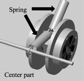
When the magnet is rotated from the attracted state, a torque in the direction opposite to the rotating direction is generated. To compensate for the torque, we attach two tension springs. Figure 6 shows the arrangement of the springs to be installed. When the central magnet changes from the neutral state of attraction and repulsion to the completely attraction state, a torque that assists rotation is generated. Utilizing this, one tension spring is pulled until the magnet is in completely attraction state. After that, the motor rotates in the opposite direction to reciprocate and returns to the neutral state again. The force that rotates the magnet at that time is compensated by the restoring force of the spring. This reduces the torque driving the actuator. In addition, both springs are installed with initial tension applied. As a result, even when the rotational magnet reciprocates, the tensile force can always be extracted from both springs.
Spring arrangement.
Torque
For the simulation, we used “JMAG-Designer” of electromagnetic simulation software.
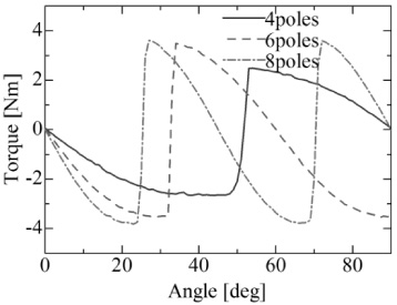
In order to determine the spring constant of the spring to be incorporated in the device, we obtained the change in torque per angle generated in the central magnet when the actuator is driven by the simulation in Fig. 7. The side magnets perform a linear motion according to the generated magnetic force. The linear motion part are not displaced according to the rotation angle, and momentarily linearly move at the moment the magnetic force changes. Figure 8 shows the relationship between the rotation angle and the torque of the central magnets obtained.
Simulation model of torque.
Relationship between the angle of the central magnets and the torque.
The maximum of the torque was the smallest for single-sided 4-pole magnets. This is because the angle of the magnet used for the 4-pole magnets is the largest, and as seen from the change in polarity in Fig. 3, the change in magnetic flux density is considered to be gentle.
Figure 9 shows the arrangement of the central magnet and springs. Figure 9(a) is a schematic view of the whole, and Fig. 9(b) is an enlarged view of the spring attachment end of the rotating magnet. The extension length X of the spring is obtained with the rotation angle of the magnet as θ. One end of the tension spring is fixed to a connecting shaft at a position A of 29 mm from the magnet rotation center O. The other end is fixed at a position B of 60 mm laterally and 55 mm vertically from the magnet rotation center. The extension length of the spring is calculated from the angle θ. In addition, the torque T for each rotation angle obtained by the simulation was converted into the force F generated at the position A. In that case, torque is generated in the tangential direction of the turning radius, so that not all the forces are transmitted to the spring. However, for the sake of convenience, the force from the torque was calculated as all accumulated in the spring. We calculated the workload from the calculated force and displacement. We determined the tension spring to use from its workload. The calculated workload was 1.63 J for 4 poles, 1.35 J for 6 poles and 1.12 J for 8 poles. Selection was made so that the workload of the spring was about half of the workload of the magnet. Table 2 shows the specifications of the springs adopted. We used Spring 2 for 4 poles, Spring 1 for 6 poles, and Spring 1 for 8 poles.
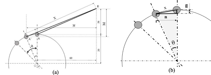
Relationship between rotation radius of magnet and spring.
Specifications of the spring used
In order to verify the performance as a pump, we experimented with water as a fluid. We compared the performance of the case incorporating the spring and the case without the spring. Also, we compared power consumption, torque and flow rate.
Experiment results (Thrust)
In order to measure the thrust of the actuator, we installed a digital force gauge on the side magnets and measured thrust. In the measurement, the side magnets are moved 10 mm in total from the magnet interval of 5 mm to 15 mm while maintaining the state of the side magnets and the central magnet in one side completely attraction and one side completely repulsion. Figure 10 shows the maximum of the thrust measured at each position for each number of poles. We confirmed the thrust of about 210–282 N when using the 4-pole magnets.
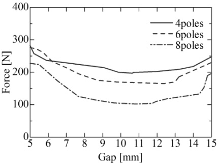
Relation between thrust and gap.
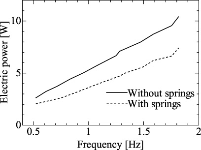
In order to confirm the torque acting on the central magnet and the load applied to the moto when the actuator was actually driven, the power consumption of the motor was measured. Figure 11 shows the relationship between frequency and power consumption when using the 4-pole magnets, Fig. 12 shows the case of the 6-pole magnets, and Fig. 13 shows the case of the 8-pole magnets. As a result, we could confirm the reduction of power consumption with the springs. We confirmed the usefulness of installing the springs from the reduction of power consumption. Also, when we compared at the same frequency, we confirmed that the state of the 8 pole magnets has the lowest power consumption. This is because the rotation angle necessary for performing one beat is the smallest in the case of 8 poles, and it was possible to perform a quick beat with a low input voltage.

Relation between electric power and frequency (4poles).
Relation between electric power and frequency (6poles).

Relation between electric power and frequency (8poles).
From the result of power consumption, we calculated the torque. Figure 14 shows the relationship between the angle and the calculated torque when using the 8-pole magnets. Figure 14 shows the change in the torque of five turns of the central magnet. The torque moves counterclockwise from A to B, C and D in the Fig. 14. In the regions A and C, it can be seen that the torque is smaller with the spring. This is because the spring compensates for the torque at the time of rotating the magnet in the completely attracted state. On the other hand, in the regions B and D, the one with the springs requires more torque. This is thought to be due to the fact that the rotational force of the motor is required in addition to the attraction force of the magnet when energy is stored by stretching the spring.
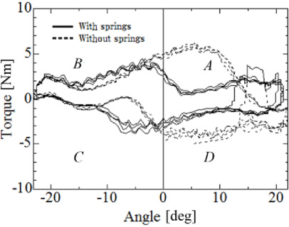
Relation between torque and angle.
Figure 15 shows the relationship between measured frequency and flow rate. The flow rate per minute for each frequency under each condition was almost constant. We also confirmed that the flow rate per minute rises according to the beat frequency even under each condition. This is because the thrust reduction of the linear actuator did not occur even if the pulsation frequency increased, so it is considered that the flow rate in one beat was kept constant. The flow rate in this system was about 2800 ml/min at about 1 Hz.

Relation between flowrate and frequency.
We developed a linear actuator with relatively little thrust fluctuation using attraction and repulsion. By utilizing the restoring force of the spring, we developed a structure that suppresses the torque required for the rotation of the magnet, and confirmed reduction of electric power by about 30% at the maximum. We were able to confirm the thrust of about 210–282 N when using the 4 pole magnets. We confirmed that the rise in the flow rate according to the frequency does not cause the thrust reduction of the linear actuator due to the increase of the frequency The power consumption in the vicinity of 1 Hz which is the resting heart rate of an adult male was about 4.2 W in the case of 4 poles, about 3.5 W in the case of 6 poles, about 3 W in the case of 8 poles. The flow rate increased in accordance with the pulsation frequency, and the discharge amount per one beat was about 47 ml.
Future challenge
With the motor currently in use, there is a limitation on miniaturization of the device, so improve the drive unit and further downsize the whole device. Investigate the change in characteristics when the flow path is a circulation system