
Abstract
In this paper, a novel three-dimensional (3-D) magnetic tester with symmetrical orthogonal excitation structure and cubic field-metric sensing structure is designed and analyzed. Automatic measurement system, which includes feedback control method, harmonics compensation, and automatic data processing is developed for the 3-D magnetic tester. In order to improve the measurement precision, cross effects of the magnetic fields in three principal directions are concerned, and error mitigation methods which fit for different excitation models are proposed. Magnetic properties of typical grain-oriented (GO) and non-grain-oriented (NGO) laminated silicon steel specimens under alternating and rotating excitations are measured and analyzed by using the designed 3-D magnetic tester.
Keywords
Introduction
Magnetic properties of the silicon steel are key factors in design and performance optimization of the electrical apparatus. Two-dimensional (2-D) measurement methods for single silicon steel sheet have been developed by some researchers [1, 2, 3, 4, 5, 6]. The previous 2-D testing methods were mainly focused on the rolling direction or the rolling plane of silicon steel. However, the silicon steels are laminated and stacked in application, which may arise magnetic interaction between the vicinity layers [7, 8]. The magnetic flux in the complicated working conditions, such as large motor and power transformer, is not completely parallel to the rolling direction or the rolling plane of silicon steel sheet. Note that a part of magnetic flux should penetrate through the laminated silicon steel which causes the error in material modeling and core loss calculation. Magnetic field in laminated direction is confirmed in T-joints of three-phase transformers, which may cause rotating core losses and increase the total core losses enormously [9]. Therefore, comprehensive magnetic properties of the silicon steel including the laminated direction should be taken into account. To guarantee the accuracy and efficiency, feedback control method should be paid much more attention to the magnetic properties measurement. An adaptive digital feedback method for 1-D and 2-D magnetic measurements was designed with multi-variable inputs and outputs [10]. The digital control of the flux loci based on contraction mapping principle showed better performance on the three-phase single sheet tester [11]. For laminated cubic specimen of 3-D magnetic testing, however, the excitation circuit is more complex and the excitation power needs to be increased significantly. Thus, the traditional control method cannot be directly extended to the 3-D condition.
Depending on the first 3-D tester and its improvement, 3-D magnetic properties of soft magnetic composite (SMC) materials have been measured and analyzed [12, 13, 14]. However, joints of the cores and yokes in the first 3-D magnetization structure are not completely uniform, which can cause structural anisotropy and influence the measurement results. In this paper, a novel 3-D magnetic tester with symmetrical orthogonal excitation structure is designed and analyzed. In order to obtain the desired magnetization loci and improve the measurement precision, feedback control method, harmonics compensation, and automatic data processing are developed. Error mitigation methods which fit for different excitation models are proposed according to different error sources. By using this tester, comprehensive magnetic properties of GO and NGO laminated silicon steels are measured and analyzed under various excitation models.
3-D magnetic testing system
As shown in Fig. 1, the 3-D magnetic properties testing system consists of excitation circuit and signal acquisition circuit. The excitation circuit mainly includes excitation signal generation unit of LabVIEW, three high performance power amplifiers and three pairs of excitation coils. And the signal acquisition circuit mainly includes six sets of
Schematic diagram of 3-D magnetic property testing system.
The excitation signals, which are generated by LabVIEW, are amplified by three channels power amplifier and then are applied to the excitation coils of 3-D magnetic tester. The 3-D magnetic tester is similar to a no-load transformer, which can realize magnetic field coupling between excitation coils and sensing coils by means of orthogonal magnetic circuits. The components of
The excitation structure consists of three orthogonal laminated cores, six multilayer excitation windings, which are wound around the three pairs of orthogonal core-poles, as shown in Fig. 2a and b. Aiming to concentrate magnetic flux density and enhance the excitation field, core poles are shaped in frustum of a square pyramid and the taper angle is about 40
3-D magnetic tester. (a) Physical diagrams. (b) Structure model.
The laminated cubic specimen with
Laminated cubic specimen with core shoes.
Magnetic field distribution of specimen surface.
The phase angle between
Cubic field-metric sensing structure. (a) Structure model. (b) Physical diagrams.
The automatic measurement system consists of inner layer waveform compensation, medium layer feedback control and outer layer automatic processing, as shown in Fig. 6. Different excitation models, such as sinusoidal alternating, elliptical and ellipsoidal rotating excitations, are supported by outer layer automatic processing. The desired waveform of magnetic flux density is obtained by feedback control algorithm and harmonics compensation. In addition, the automatic measurement system can realize measurement status monitoring, measurement queue setting, magnetization stability time delay, output recording and online processing.
Schematic diagram of the automatic measurement system.
In general, the dynamic magnetic properties measurement of soft magnetic materials is performed under steady and periodic magnetization excitation. Therefore, the signal frequency spectrum analysis and frequency domain control can be more effective than that in time domain. As shown in Fig. 7, frequency domain control system is established, in which the digital controller can regulate the PI parameters automatically according to the magnitude and frequency of
Control flow chart of 3-D testing in frequency domain.
The mutual coupling of excitation windings should be taken into account in control of excitation signals. The independent control of excitation signals in three directions is achieved by
To overcome distortion in the
Control flowchart of harmonic compensation algorithm.
The ratio of harmonics to fundamental components in the x axis under rotating magnetic measurement (a) without harmonics compensation. (b) With harmonics compensation.
Based on the Faraday Law of Electromagnetic Induction, the
where
It is confirmed that the inaccuracy of measured magnetic properties under rotating excitations is due to the cross effects of non-measuring directions and the misalignment of coil, as shown in Fig. 10. For
where
The equivalent cross-section area of the minimized coils is difficult to obtain, which leads to the coil coefficient cannot be precisely calculated by Eq. (5). Hence, the tensor coefficient method is proposed and performed in 3-D testing to calibrate the coefficients of
Averages of diagonal coefficients for
Scheme of induction voltages for the 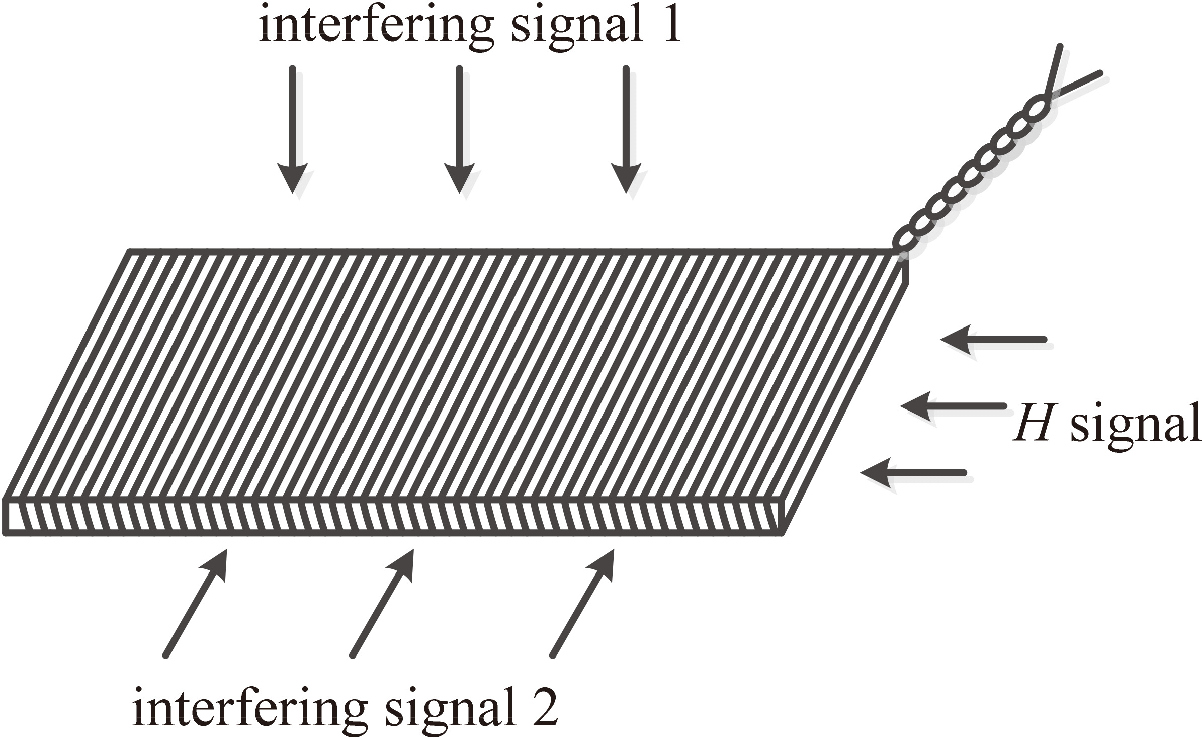
CW, CCW and average rotational 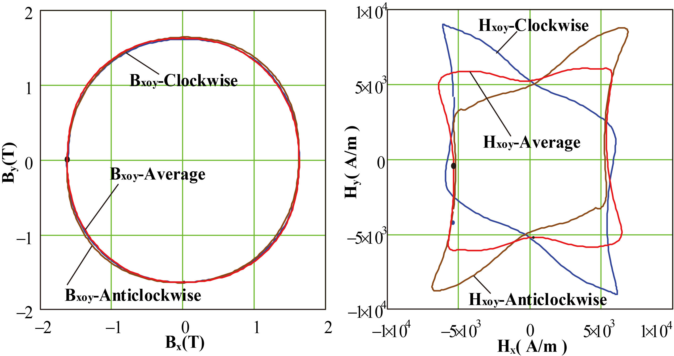
Hysteresis loops of the NGO 35WW270 in three directions at 50 Hz. (a) Rolling direction. (b) Transverse direction. (c) Laminated direction.
In this paper, the method of averaging clockwise (CW) and anticlockwise (CCW) outcomes is employed under rotating excitations. For circular rotating magnetic field, the components of magnetic field strength
where
Hysteresis loops of the GO 27ZH95 in rolling and transverse directions at 50 Hz. (a) Rolling direction. (b) Transverse direction.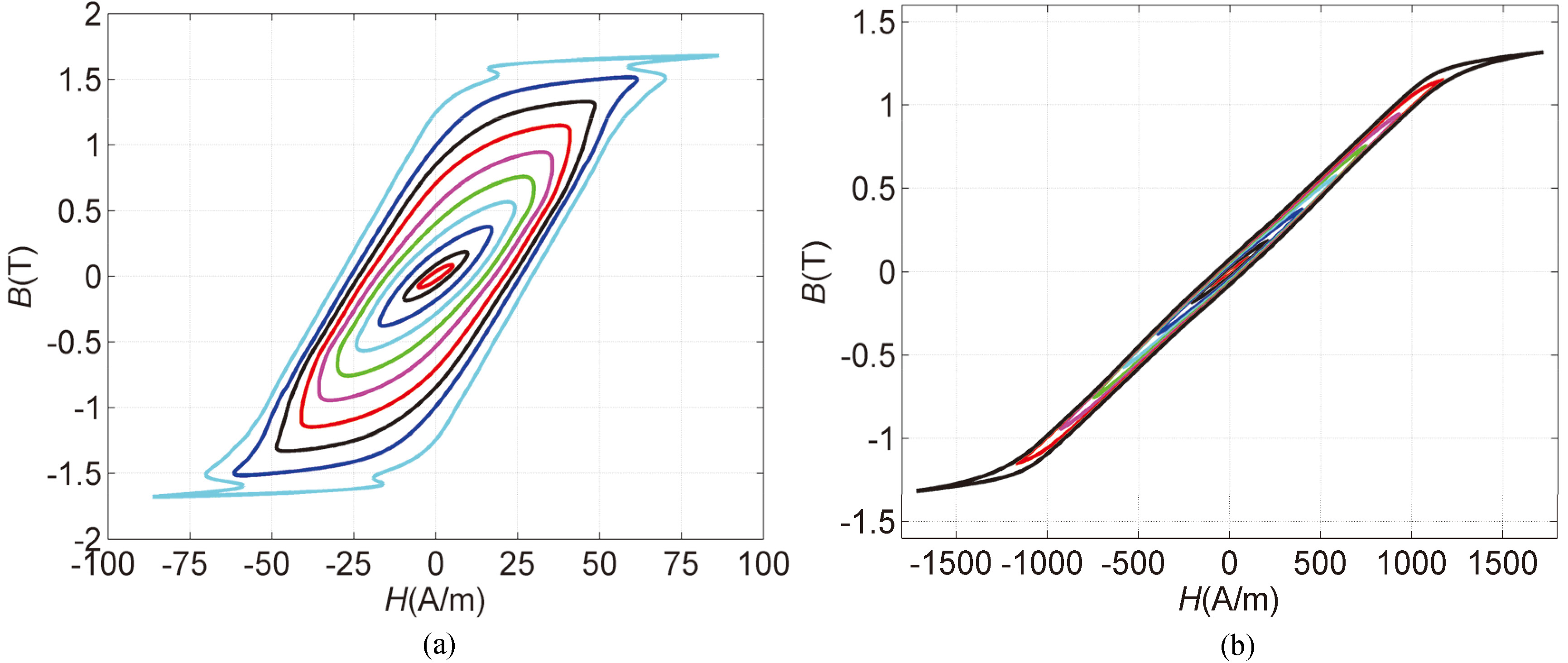
Alternating core loss in the rolling and transverse directions at 50 Hz.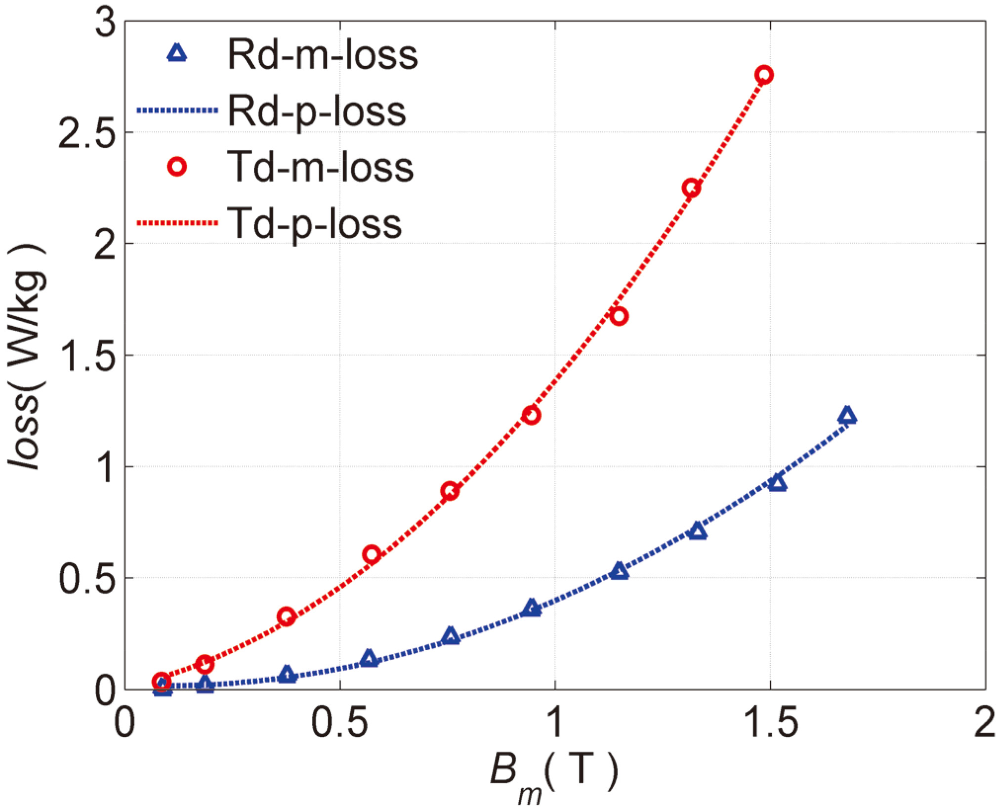
Typical GO 27ZH95 and NGO 35WW270 silicon steels are made into laminated cubic specimen respectively. Meanwhile, the magnetic properties under alternating excitation in three directions, circular and 3-D ellipsoidal excitations are measured systematically. The core losses under different excitation models can be directly calculated by Poynting’s vector theorem.
Alternating magnetic properties
The alternating magnetic properties measurement of laminated silicon steel specimens is progressed when the
For the NGO silicon steel specimen, the hysteresis loops along the rolling, transverse and laminated directions are measured and compared by improved flexible multi-layer windings at 50 Hz, as shown in Fig. 12. It can be seen that saturation magnetic flux density of the NGO silicon steel is approximately up to 1.5 T. In addition, the hysteresis loops of NGO silicon steel represent favorable coherence along the rolling and transverse directions. Due to the leading role of air permeability, the laminated direction is the most difficult magnetization direction and the permeability is approximately linear, which is mainly determined by the stacking coefficient of specimen. Equivalent permeability can be expressed as
where
In Fig. 13, the hysteresis loops are measured along the rolling and transverse directions of GO silicon steel specimen. The rolling direction is the easiest magnetization direction, which saturation magnetic flux density is approximately up to 1.8 T. The permeability of GO 27ZH95 silicon steel along the rolling direction is far higher than that along the transverse direction, which represents strong magnetic anisotropy. In Fig. 14, the alternating core loss are obtained by measured and calculated respectively. It can be observed that the alternating core loss of rolling direction is less than the transverse direction.
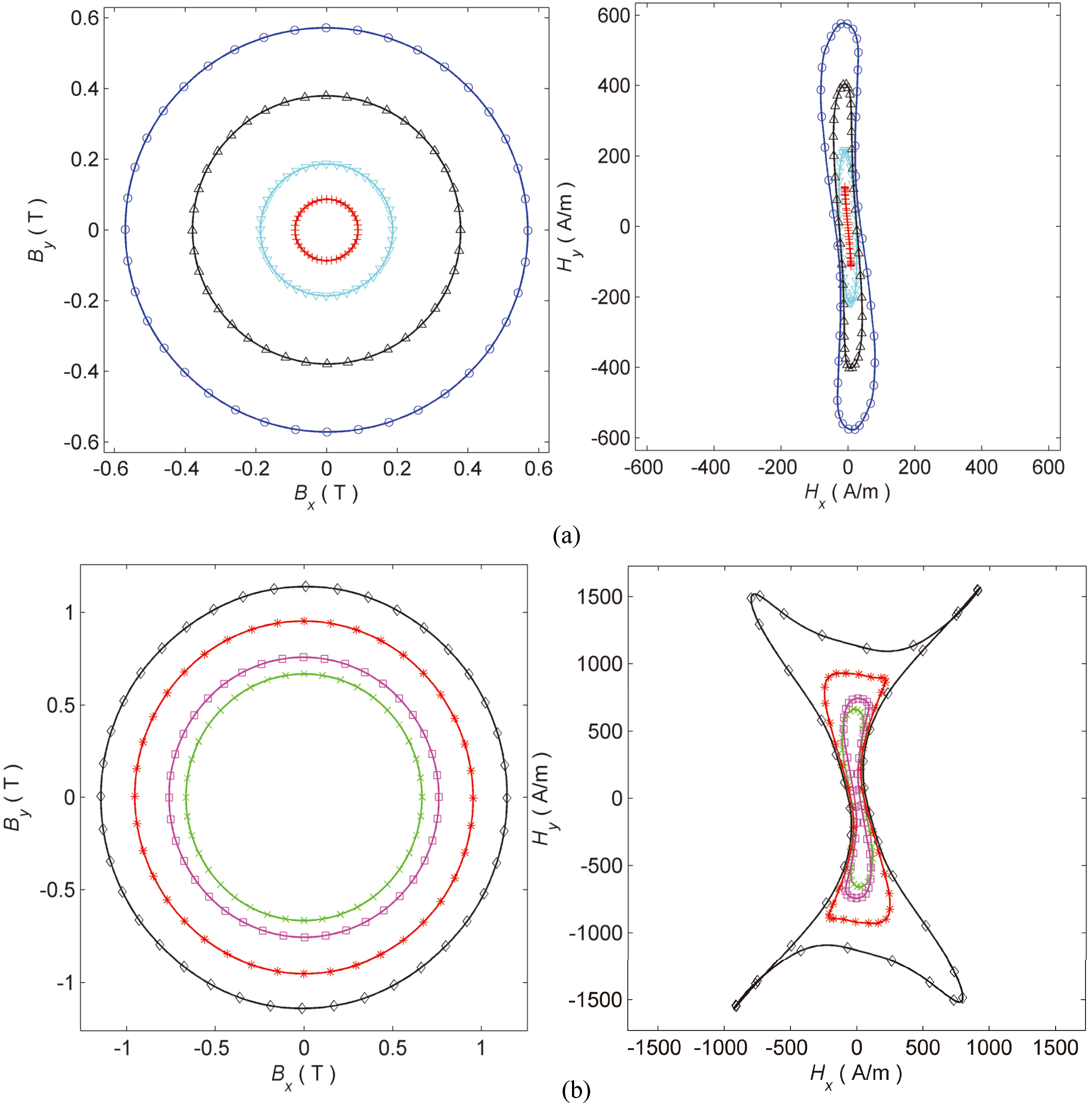
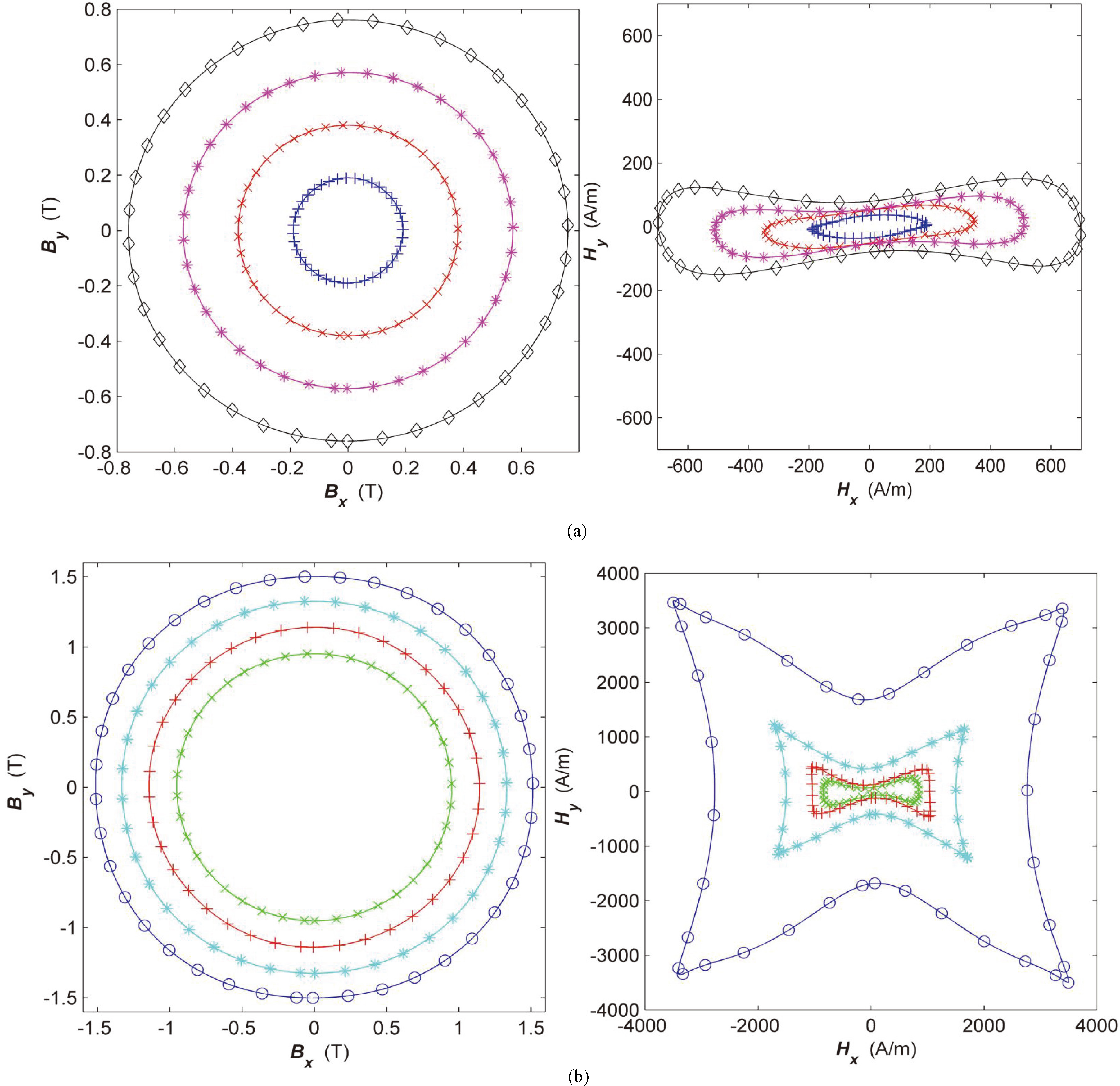
To analyze magnetic anisotropy comprehensively and provide reliable data to calculate core loss accurately, the rotating magnetic properties of GO and NGO laminated silicon steel specimens are measured respectively. When the magnetization loci are controlled to be circle, the
For the GO 27ZH95, the
For the NGO 35WW270, the
Core loss analysis
Alternating core losses per cycle along rolling direction of the NGO 35WW270 are calculated and compared at 50 Hz, 100 Hz and 200 Hz, as shown in Fig. 17. It can be found that the total losses are evidently increased with excitation frequency, which is caused by classical eddy loss and excess loss. Figure 18 illustrates the rotating core losses in the rolling plane for the NGO 35WW270 at 50 Hz, 100 Hz and 200 Hz. It can be seen that the rotating core loss increase to peak value when the magnetic flux density is approximately 0.8 T and then gradually decreasing. The magnetic domain walls gradually disappear by the increasing of magnetic flux density, the hysteresis loss decreases while the classical eddy loss increases, so the total rotating core losses may decrease.
Alternating core losses per cycle along rolling direction of the NGO 35WW270 at 50 Hz, 100 Hz and 200 Hz.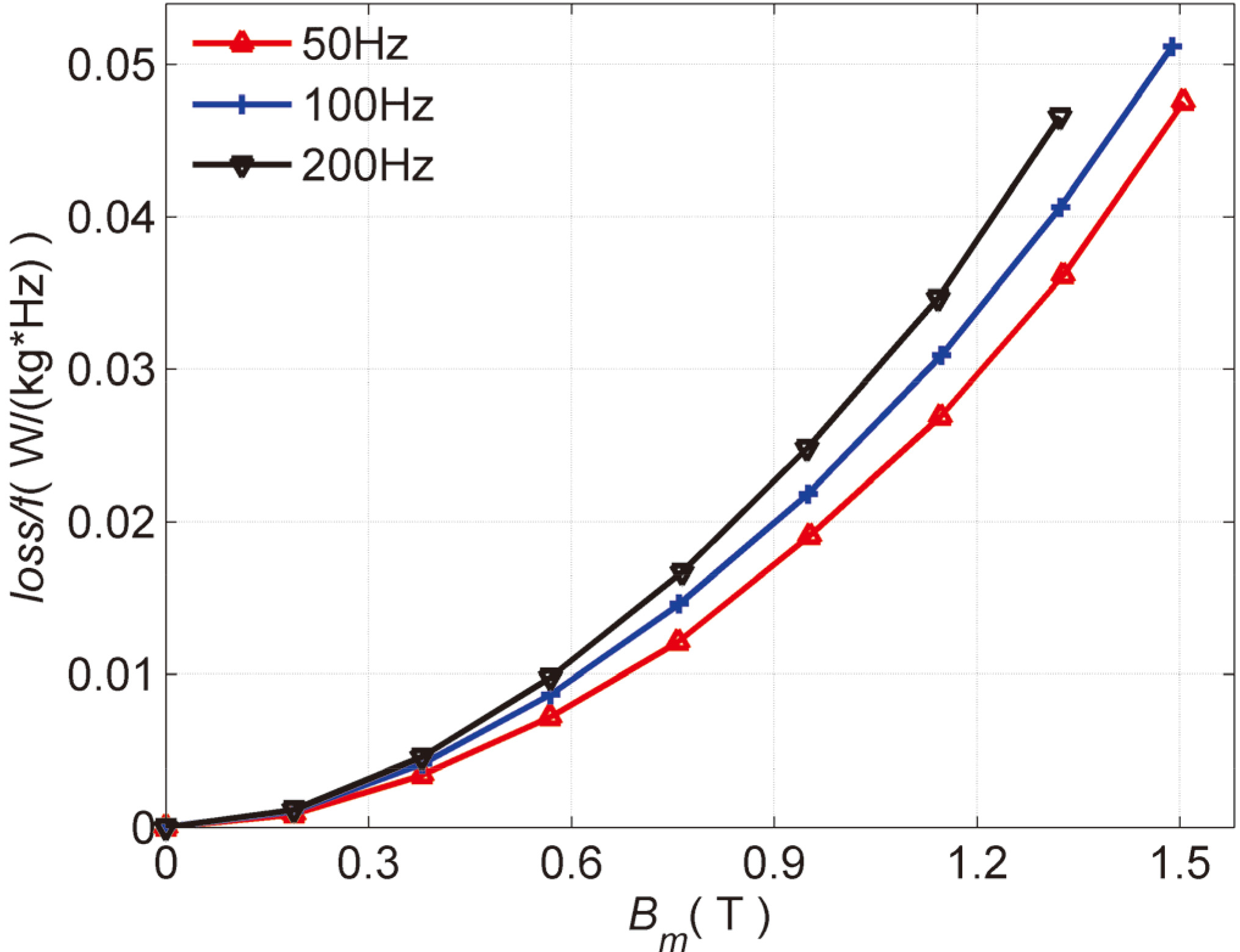
The rotating core losses in rolling plane of the NGO 35WW270 at 50 Hz, 100 Hz and 200 Hz.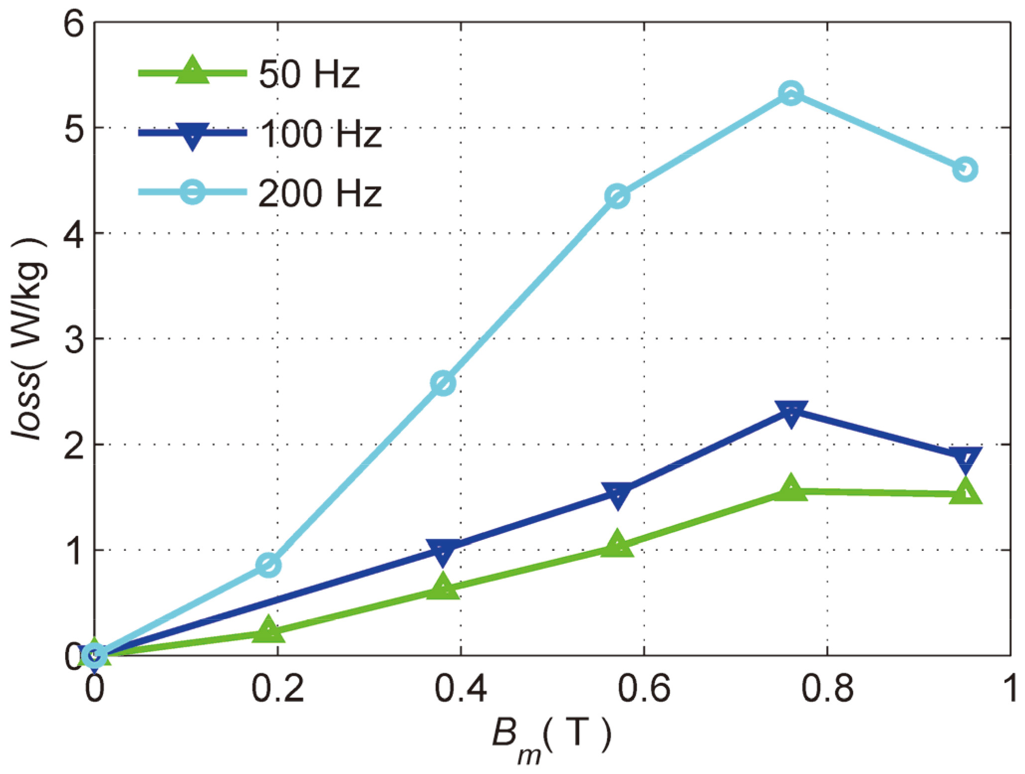
The hysteresis, classical eddy and excess losses in three directions at 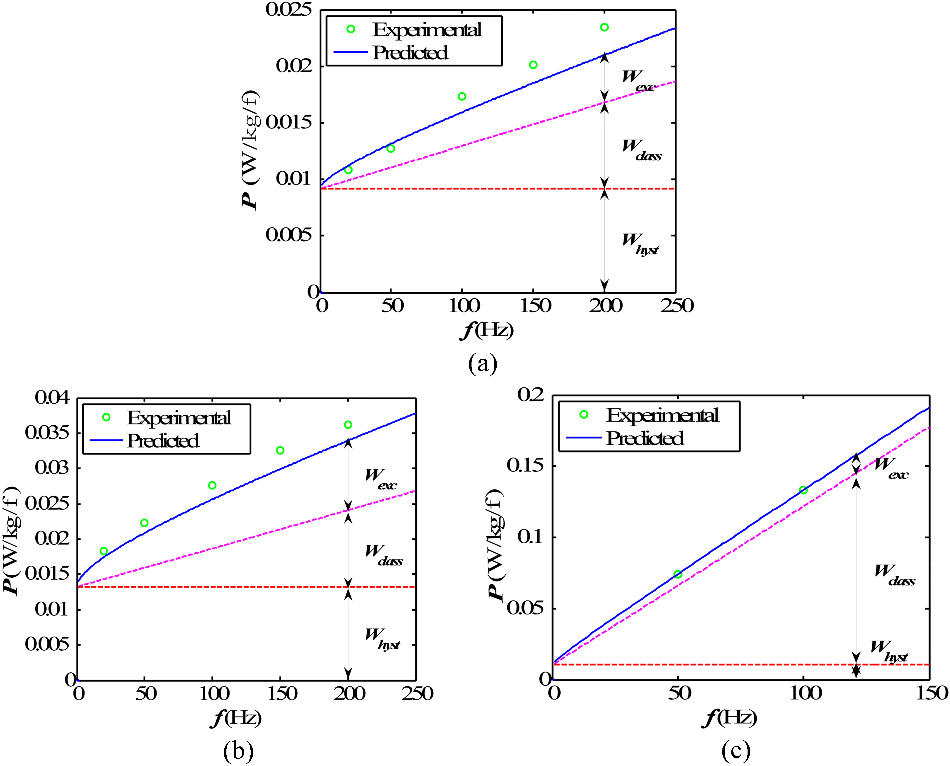
In order to quantitatively study the alternating hysteresis, eddy current and excess losses, total losses separation is performed by Eq. (7).
where
The hysteresis loss per cycle
In this paper, a novel 3-D magnetic testing structure consists of three orthogonal “C-type” cores with laminated HiB silicon steel is designed and modeled. The concentrated poles can generate relatively uniform and high magnetic field. The enclosed sensing structure with homogeneous field core shoes may ensure uniformity of the sensing field. Desired magnetization loci can be obtained by feedback control algorithm and positive compensation. Meanwhile, measurement precision is guaranteed by combining tensor coefficient and the averaging of CW and CCW outcomes.
By using the novel 3-D magnetic properties tester with feedback control, harmonics compensation, and automatic data processing, the comprehensive magnetic properties of laminated silicon steel are measured and analyzed. Alternating magnetic properties for laminated silicon steel in different directions are obtained, especially in the laminated direction, which is rarely studied but important to practical application. The magnetic anisotropy of GO 27ZH95 and NGO 35WW270 laminated silicon steels are compared and analyzed from origin of magnetic anisotropy. Alternating core loss features of the NGO 35WW270 laminated silicon steel along three directions are calculated and compared at 50 Hz, 100 Hz and 200 Hz. Alternating hysteresis, eddy current and excess losses are obtained by total losses separation. Moreover, the rotating core losses in rolling plane of 35WW270 are measured and analyzed at different excitation frequencies.