
Abstract
Detectability of an artificial slot, placed at the bottom of a steel plate was investigated by the method of Magnetic adaptive testing (MAT), when the measurement was performed through another steel plate. Influence of an air gap (or of a nonmagnetic spacer) located either between the magnetizing yoke and the top plate surface or between the two plates was explored. It was found that if the thickness of the nonmagnetic spacer was not larger than 0.15 mm, it had no influence on the detectability of the slot in the given geometry. This result shows an excellent applicability of MAT, and it is encouraging for possible future practical applications. The empirical data were compared with results of an electromagnetic simulation, and the outcome was interpreted and explained.
Introduction
Local wall thinning is a very serious and frequent defect type in pipes used in industry [1, 2]. To avoid severe accidents, inspection of the thickness reduction of pipes is a very important task. Several nondestructive testing techniques, such as X-ray [3], microwave [4] ultrasonic [5, 6, 7], acoustic emission [8, 9, 10], eddy current [11], thermal infrared measurements [12] and others are used for the evaluation of the pipe wall thinning. The magnetic flux leakage (MFL) method is also a frequently used pipeline testing technique [13, 14, 15, 16, 17, 18].
In most cases the wall thinning inspection should be done from the outer side of the pipe, because – even though this phenomenon frequently occurs inside the tube due to the stream of coolant flowing inside the pipe – long length of the pipe usually prevents any testing from inside. A more difficult problem is to detect the local wall thinning at locations under an enforcement shield that covers the pipe outside where a branch pipe is connected to the main one. Because the enforcement shield and the pipe wall form two layers of metal, it is difficult to inspect the inner side of the pipe under the enforcement shield by any ultrasonic method. Pulsed eddy current testing technology was developed in recent years to challenge this problem [19, 20, 21]. In this case the targets are non-ferromagnetic materials, and due to the rich frequency spectrum and the applicability of large electric current, pulsed eddy current method shows promising capability in the detection and evaluation of defects in deep regions of the material.
If pipes are made of ferromagnetic materials (e.g. steel), magnetic methods are also suitable electromagnetic nondestructive testing methods for the inspection of local wall thinning even at locations under enforcement shields. The feasibility of the application of the magnetic flux leakage (MFL) method for the investigation of wall thinning of pipes under reinforcing plates was discussed. Assessment of size of a slot fabricated on the under-layer of a layered specimen was shown to be possible from the flux leakage profile. It was also shown that conditions of wall thinning under reinforcing plates can be monitored by the MFL method [22, 23]. Another example, a recently developed nondestructive method, called Magnetic adaptive testing (MAT), which is based on systematic measurement of minor magnetic hysteresis loops, was applied for the detection of local wall thinning in ferromagnetic plates. It was shown that even a relatively small, local modification of the sample thickness could be detected with adequate signal/noise ratio from the other side of the specimen. The measurements gave good results also, if the investigated plate was covered by other plate(s) [24, 25].
In spite of a great number of publications in this area, the influence of an air gap/nonmagnetic spacer between the magnetizing yoke and the sample surface is discussed in a very limited way. In practical cases some air gaps always necessarily exist, even between polished surfaces, the question is only the thickness of the air gap. The surfaces of tubes, and other objects to be inspected are frequently painted, which by itself produces a nonmagnetic spacer, not to speak about the frequent case, where the surfaces are rough, dirty or corroded. The problem becomes even more pronounced if the wall thinning to be detected is under an enforcement shield, because in this case also some air gap – due to the surface roughness of the plates – always exists between the two ferromagnetic plates. In an earlier work [26] with MAT measurements we intentionally applied non-magnetic spacers (with thicknesses of 0.08 mm and 0.23 mm) for relative indication of the samples’ micro-structural conditions. It was shown that the spacers modify shapes and size of the measured signals, and they substantially reduce scatter of experimental points. Sometimes, with thick spacers in particular, they are able to modify shapes of the measured signals qualitatively and even to bring about considerable increase of sensitivity, especially if the degradation functions are computed from the signal derivatives.
The purpose of the present work is to investigate and to analyze the influence of the air gaps – which is nothing else but a nonmagnetic spacer between the plate surfaces – in local wall thinning experiments performed by MAT. We investigate how the artificially applied nonmagnetic spacer between a magnetizing yoke and a sample surface, and also between the two plates, influences the measured signal, and the detectability of the artificially made slot in the bottom plate. Especially we investigate what is the thickest nonmagnetic spacer, which still makes possible (in the case of the given configuration) the detection of local wall thinning. Some experimental results are compared with a numerical simulation.
Samples
Two low carbon commercial steel plates of size 500 m
Simulation of the magnetic flux change
The variation of the magnetic flux density in the cross section of the magnetizing yoke due to the presence of the artificial slot was calculated by the AC/DC Module of the Comsol Multiphysics
Relative change of the magnetic flux (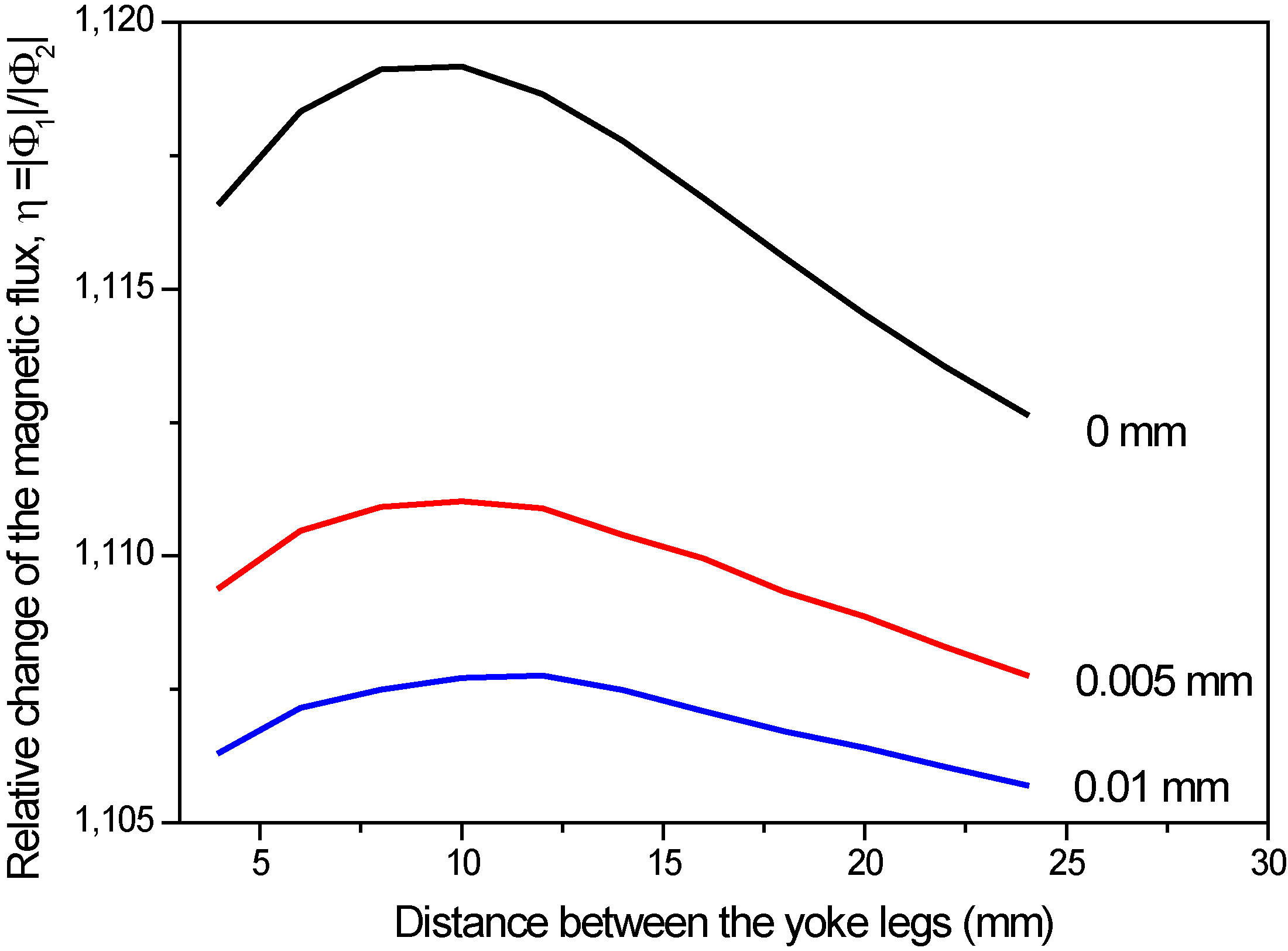
It is seen in Fig. 1 very well, how significantly the relative magnetic change due to the presence of the slot is decreased with the increased air gap. For even better illustration of the influence of the air gap, Fig. 2 shows how the maximum of the relative flux change (peak values of the curves in Fig. 1) depends on the thickness of the air gap in the double layer configuration with a 10 mm wide slot. In this case the relative change of the magnetic flux is shown for a significantly wider range of air gaps.
Sketch of the measurement configuration, when a nonmagnetic spacer is applied between the surface of the plate and the magnetizing yoke.
Magnetic adaptive testing was used for the magnetic measurements. This method is described in detail in [28]. Series of minor magnetic hysteresis loops were measured using a yoke for magnetization of the samples. The yoke was a C-shaped laminated Fe-Si transformer core, placed directly on the plate to be measured. When equipped with a magnetizing coil and a pick-up coil, the yoke is called the “measuring head”. Lateral dimensions of the measuring head are characterized by its cross-section:
The magnetizing coil gets a triangular waveform current with step-wise increasing amplitudes and with a fixed slope magnitude in all the triangles. This produces a triangular time-variation of the effective field in the magnetizing circuit and a signal is induced in the pick-up coil. As long as the field sweeps linearly with time, the voltage signal in the pick-up coil is proportional to the differential permeability of the magnetic circuit. The Permeameter works under full control of a PC computer, which registers data-files for each measured family of the minor “permeability loops”.
The experimental raw data are processed by an evaluation program, which divides the originally continuous signal of each measured sample into a family of individual permeability half-loops. The program filters experimental noise and interpolates the experimental data into a regular square grid of elements,
The matrices are processed by another evaluation program, which divides values of their elements by corresponding element values of a chosen reference matrix (i.e. matrices standardization), and arranges each set of the mutually corresponding elements
The matrix-evaluation program calculates also sensitivity of each degradation function and draws their “sensitivity map” in the plane of the field coordinates (
In this measurement it is difficult to determine exact values of the magnetic field, h, inside the sample, due to the open magnetic circuit. Because of this the magnetizing current,
Analyzing the measured MAT parameters, taking into account accuracy of the measurement and repeatability of the measured values, error of the MAT descriptors is estimated about 5%.
When any magnetic
Sketch of the measurement configuration, when a nonmagnetic spacer is applied between the surface of the plate and the magnetizing yoke.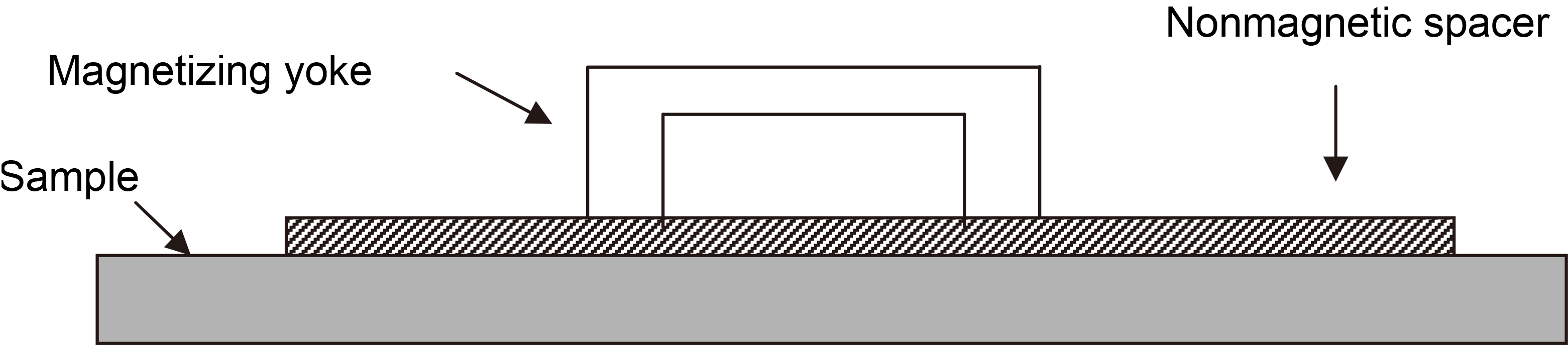
Drop of the signal due to spacers
To illustrate how the existence of a nonmagnetic spacer modifies the measured signal (i.e. the permeability minor loops), we compared signals of the pick-up coil for the cases with and without the spacer. For the comparison only one plate without the slot was measured as shown in Fig. 3. Thickness of the used spacer is 0.075 mm. The large difference between the signals is clearly seen in Fig. 4: permeability drops down as a consequence of the nonmagnetic gap between the surface of ferromagnetic plate and the magnetizing yoke. The thicker is the gap, the more the signal drops down.
Signal of the pick-up coil measured on the plate without the slot. Measured signal with and without application of the spacer between the sample surface and the magnetizing yoke.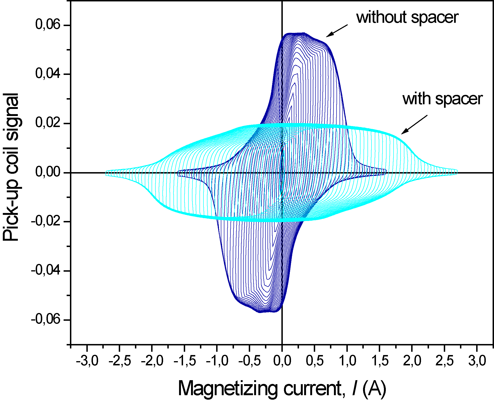
The main measurements were performed on two steel plates with the magnetizing yoke attached to the top surface of the top plate, which did not have any slot. The artificial slot was always located at the bottom of the bottom plate. Figure 5 shows the sketch of the measurement, when a spacer was applied. During measurement of the degradation functions the magnetizing yoke was moved step by step over the surface along a line, which was perpendicular to the length of the slot. The vertical distance,
Sketch of the measurement. The arrow indicates the direction of the movement of the magnetizing yoke.
Optimally chosen 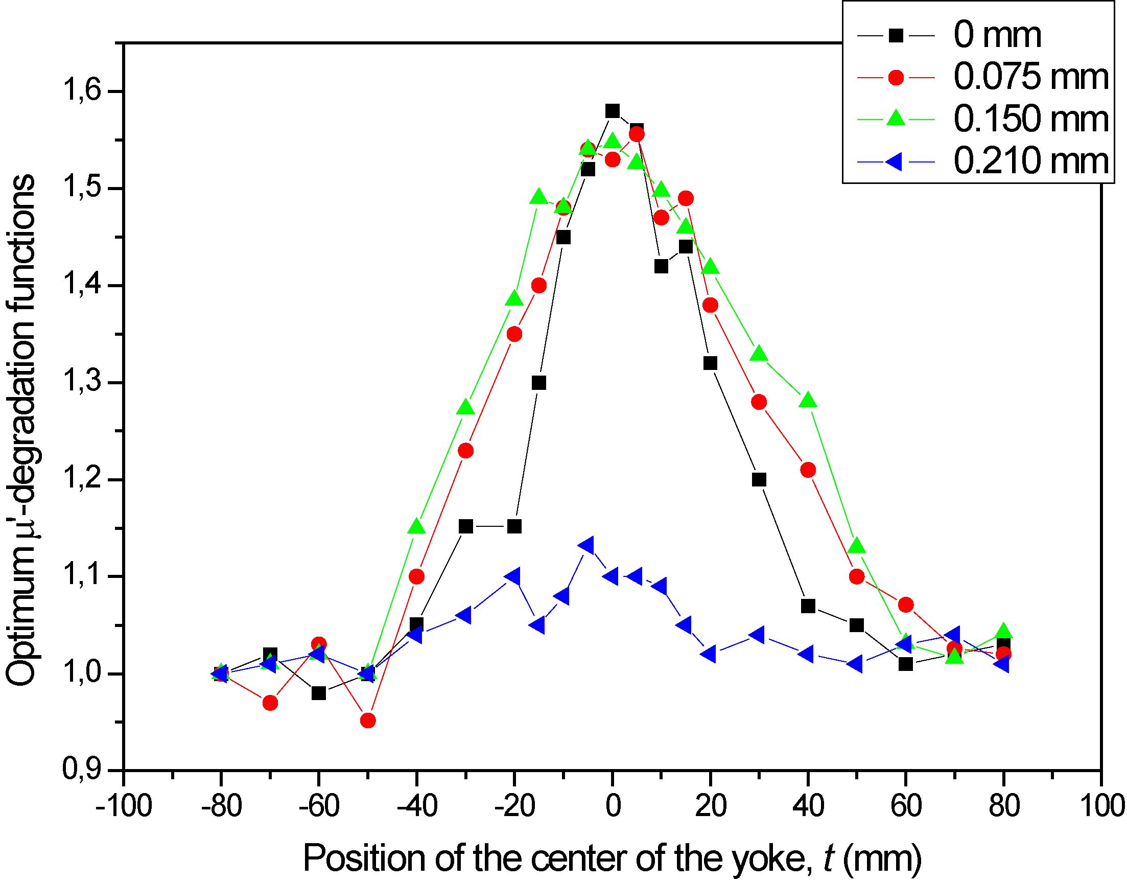
Map of relative sensitivity of the 
MAT measurements were performed for two arrangements: in one of them nonmagnetic spacer or spacers were placed between the top plate and the magnetizing yoke, in the other one the spacer or spacers were placed between the two plates. (In this latter case there was no spacer between the yoke and top plate.) Results of the MAT measurements are shown in Fig. 6 for the case where spacers were placed between the yoke and the top plate. Figure 6 contains the results of four independent measurements: 0 mm, 0.075 mm, 0.15 mm and 0.21 mm thick spacers were applied. The optimally chosen MAT degradation functions are shown for the three spacer thicknesses and for the reference case (no spacer). At position “
During evaluation of the great number of possible MAT parameters always those degradation functions are chosen for the presentation, which are the most sensitive for the given material deformation/ degradation. In the present case the derivative
Sketch of the measurement. A nonmagnetic spacer is applied between the two plates.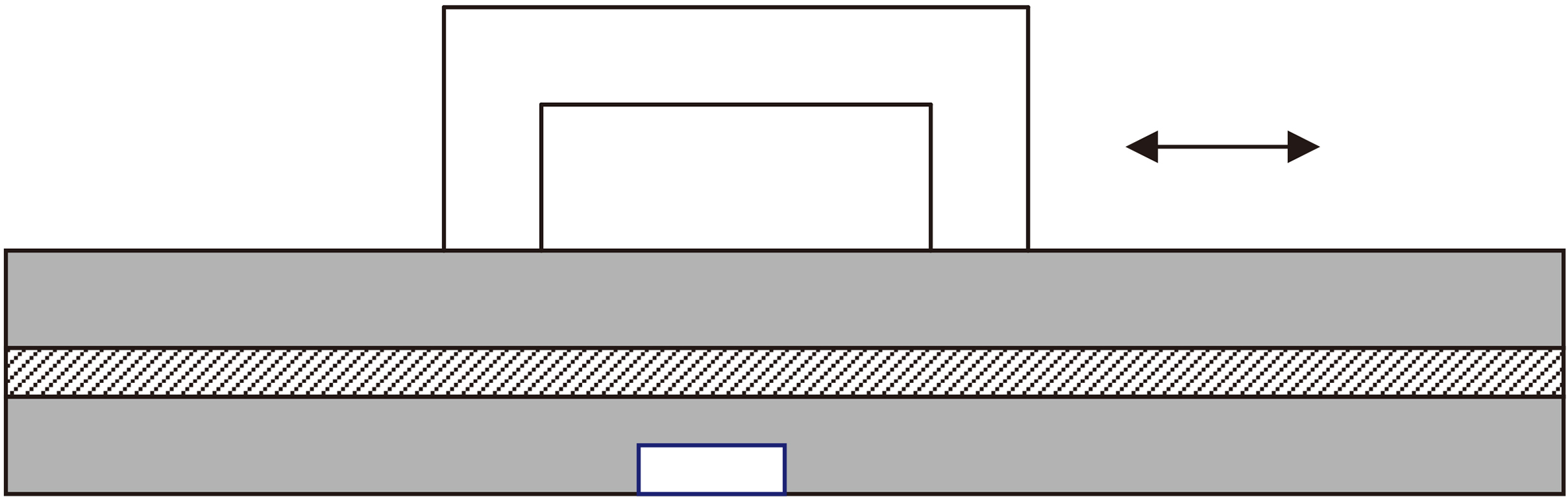
Optimally chosen 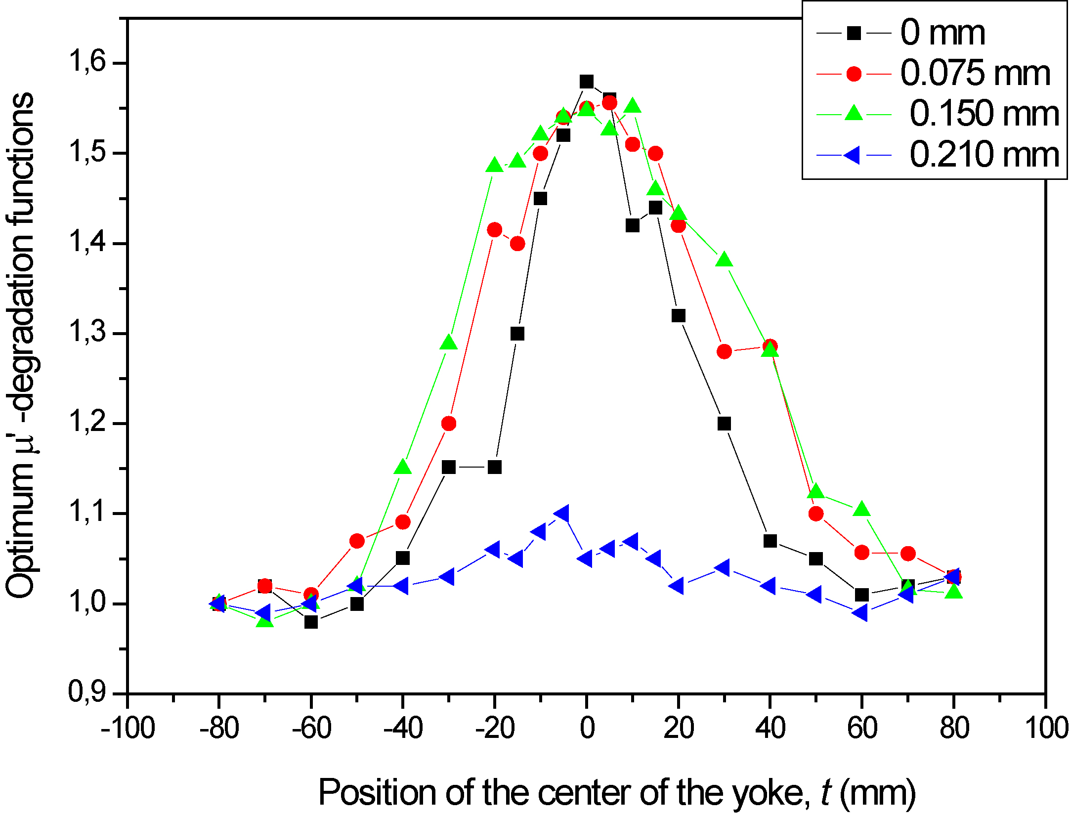
It is well known that in general derivatives can be notoriously noisy and usually associated with low signal to noise ratio (SNR). However, based on the sensitivity map (mentioned above) it is possible to determine, how robust is our
In another arrangement the nonmagnetic spacer/spacers were placed between the two plates, as indicated in Fig. 8. Again, spacers with three different thicknesses (0.075 mm, 0.150 mm and 0.210 mm) and the reference case, without spacer were applied. The results are given in Fig. 9.
For the sake of the complete investigation, an arrangement was also investigated, where one spacer was placed between the yoke and the top plate surface, and another one between the two plates. Very similar results to those shown in Figs 6 and 9, were obtained (not presented here), where the total sum of thicknesses of the two spacers was considered.
All other possible configurations of the three spacer applications were also studied, but in all cases when the total thickness of the nonmagnetic spacers was increased to 0.21 mm, the result was not satisfactory, similarly to the case, shown in Figs 6 and 9 for 0.21 mm spacer: no reliable detection of the artificial slot in the bottom plate was possible. Some indication of the slot is seen, the
It is evident from the measurements that the slot was clearly detectable in the given arrangements, in accordance with our previous experience. Existence of the 10 mm wide and 3 mm deep slot generated more than 50% change in the optimally chosen MAT
Purpose of the present work is to analyze the influence of the air gap (and/or of the nonmagnetic spacer) on detectability of an artificial slot existing in the tested ferromagnetic plate. It is well known that the air gap is an important factor of the measurement, and in our present work we gave an empirical, quantitative estimation for the maximal thickness of the air gap, which still makes possible the detection of the slot in the given arrangement.
It was found that even a 0.15 mm thick air gap does not cause remarkable decrease in the variation of the properly chosen MAT degradation function. In the double plate arrangement, position of the air gap between the magnetizing yoke and the top plate surface is equivalent to its position between the two plates, and in case that there are air gaps both in the former and in the later position, their influence is simply summed up. This result is rather encouraging for possible practical applications.
Simulation results revealed that the slot-dependent change of the magnetic flux density in the “yoke-plates” open magnetic circuit decreases rapidly by increasing the air gap. It can be determined from Fig. 2 that the magnetic flux change due to the presence of a slot is less than 1 percent if a 0.15 mm wide air gap is considered in the given geometry. In spite of this fact, the slot can be well detected by the Magnetic adaptive testing. This experience shows an excellent applicability of MAT even in this case.
The possible explanation of this unexpected sensitivity is that during the MAT evaluation the derivative of permeability is used. Due to any air gap the flux density in the open magnetic circuit decreases dramatically – as proved by the simulation – but the primarily measured signal (which is shown in Fig. 4) is proportional to the differential permeability,
Next factor, which supports the good results is, that the degradation functions are always normalized by a reference value (The reference value in this case is the level of the corresponding degradation function measured far from the position of the slot, i.e. the “no-slot” level). It means that even a small difference becomes large by this normalization.
It may seem surprising that the evaluated experimental curves (Figs 6 and 9) practically do not depend on thickness of the air gap in the investigated range. This fact seems to be in contradiction both to the results of simulation (Fig. 2), and to the significant decrease of the permeability curves shown in Fig. 4. However, the explanation is again the normalization: the larger air gap results in lower permeability, but these lower
It is seen in Figs 6 and 9 that for larger air gaps the shape of the
Conclusions
Detectability of a 10 mm wide and 3 mm deep artificial slot, placed at the bottom of a 6 mm thick steel plate was investigated by Magnetic adaptive testing when the measurement was performed through another 6 mm thick steel plate. Role of an air gap between the magnetizing yoke and the top plate surface and also between the two plates was studied. It was found that if the thickness of the air gap (or sum of the thicknesses of air gaps) was not larger than 0.15 mm, it had no influence on detectability of the slot. This result shows the excellent applicability of MAT in this case, and it is encouraging for possible future practical applications.
The empirical results were modelled by electromagnetic simulation and it was shown that air gap caused a dramatic decrease of the relative change of the magnetic flux, due to the presence of a bottom slot. However, in spite of this big change, detection of the slot is possible with a good signal/noise ratio. This result was interpreted and explained.
Footnotes
Acknowledgments
This work was supported by the Hungarian Scientific Research Fund (project K 111662), by the Researcher Exchange Program between the Japan Society for Promotion of Science and Hungarian Academy of Sciences, and by the Researcher Exchange Program between the Czech Academy of Sciences and Hungarian Academy of Sciences. The co-author I.T. also appreciates financial supports by project No. 14-36566G of the Czech Science Foundation. The work was also partly supported by the JSPS Core-to-Core Program “Advanced Research Networks: International research core on smart layered materials and structures for energy saving”.