
Abstract
Magnetic-bearing reaction wheel (MBRW) can be applied to stabilizing satellites with stringent pointing accuracy. Temperature rise subjected to losses is a key issue for a MBRW. The prediction models of iron loss and copper loss for magnetic bearings and BLDCM are established, and the loss coefficients of iron core are determined by measured loss curves at different frequencies. The copper loss distribution and iron loss distribution of the MBRW are investigated. Based on the loss values, the heat generation rates of the different parts in the MBRW are calculated, then the thermal field of the prototype is analyzed by 3-D finite element model. Thermal-structure coupled analysis of rotor is also investigated. Finally, the prediction and analysis of losses are verified by experimental results in a prototype of MBRW with rated speed of 5000 r/min and rated angular momentum of 15 Nms.
Introduction
Satellite remote sensing of the earth is stabilized by three-axis spacecraft in order to meet the fine pointing accuracy requirements of the payloads [1,2]. Reaction wheel (RW) serves as actuator to stabilize the attitudes of the satellite. The pointing precision of the satellite declines due to the friction torque spike in mechanical bearing RW under the conditions of cross through zero speed. Also, unbalanced vibration in the dynamic friction with rotational speed, temperature, lubrication, and operation history are shortcomings of the mechanical bearing RW. In order to avoid the aforementioned shortcomings for improving pointing performance of satellite, magnetic bearing RW (MBRW) has been the subject of intense research. The outstanding advantages of MB are no lubrication, no wear, and low rotational losses. Other performances obtainable with MBs, are the absence of frictional drag torque effect and can suppress the unbalanced disturbance through the active vibration suppression [3–6]. Therefore, the MBRWs are ideal actuators for the satellites, which enable remarkable improvements in the properties of the attitude control system for the satellite application. But, temperature rise of the MBRW subjected to losses is a key issue for satellite application.

Section view of the MBRW.
In the MBRW, the copper loss and iron loss in the MBs and the brushless direct current motor (BLDCM) are the component loss. These losses will produce an increase of temperature rise in the MBRW. The temperature rise will lead to the increase of stress in the MBRW. Another potential problem associated with the temperature rise may also weaken the performance of the permanent magnet material in the MBRW. Therefore, it is very important to calculate the loss and conduct the thermal analysis in the MBRW. The calculation methods of copper and iron loss in electrical machine are used for reference. In Ref. [7], the influence factors of the ac copper losses in an ironless brushless DC motor are analyzed. An eddy current loss analysis method in the retainer of the PM machine with high-power-density is proposed [8]. The calculation model of a doubly salient generator (DSG) is established, and its iron loss distribution of the DSG is investigated [9]. In Ref. [10], the performances of a surface-mounted PM motor (SMPMM) and a hybrid magnetization interior PM motor are compared, with particular reference to losses and temperature rise. The core losses in a high-speed switched-reluctance machine are predicted [11]. The rotor eddy-current losses and iron losses in both motor and generator are calculated by Nannan Zhao, etc. al. [12]. Based on the Bertotti loss model, the rotating loss separation method is proposed [13]. The losses of a high-speed PM synchronous machine with magnetic bearings are predicted with analytical calculation and compared with measured results [14]. The losses prediction and thermal analysis of a high-speed rotor supported by MBs are proposed [15].
The MBRW can be applied to stabilizing satellites with stringent pointing accuracy compared with traditional ball bearing RW, but few literatures systematically predict its losses and conduct an accurate thermal field analysis. Jinji Sun [16] analyzed the eddy current loss in homopolar magnetic bearings for the aerospace applications, but other loss components are not considered. Shuna Zhang [17] conducted thermal and structural coupling analysis of magnetically suspended flywheel rotor by using 2D FEM, however, this paper did not give the loss calculation model. In Refs [18] and [19], a thermal design method combining finite element and thermal network model is presented for magnetically suspended reaction flywheel and control moment gyro, however, the loss calculation model in these two papers are too simple to be accurate. In this paper, an accurate thermal field analysis considering all the losses and the special ways of heat transfer in MBRW is proposed by the authors. Besides, the influence of temperature variation on the maximum equivalent stress is addressed by thermal-structure coupled analysis for thermal stress problems.
The originality of this paper is to systematically deal with the loss estimation, thermal analysis, and thermal-structure coupled analysis in the MBRW. The loss prediction and thermal analysis results are verified by the measured value of the prototype.
The section view of the MBRW is shown in Fig. 1. The MBRW consists of a BLDCM, two radial/axial sensors, two radial MBs (RMBs), a pair of axial MB (AMB), a cover, a rotor, and a base. To reduce the power consumption of the MBRW, the rotor is driven by an ironless BLDCM, and supported by the MBs with PM bias.
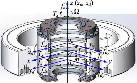
Force analysis and torque analysis of the rotor.
Figure 2 shows the force and torque analysis of the rotor supported by MBs. The 6 degrees of freedom of the rotor are controlled by two RMBs, an AMB, and a BLDCM. oxyz is the rotor center-of-mass reference coordinate system, o
u
x
u
y
u
z
u
and o
d
x
d
y
d
z
d
denote the upper and lower RMB’s coordinate system, respectively. The dynamic equation of the MB-rotor system is given by
The rotation speed is controlled by the BLDCM, MBRW that consume low power are particularly suitable for space applications. Thus, a 3-phase ironless BLDCM is applied in this paper (Fig. 3) [20,21]. The stator consists of winding coils and stator frame for holding winding coils and Hall sensors. The rotor is composed of permanent magnet poles, outer rotor core, and the inner rotor core. SmCo magnet is used in the BLDCM. Table 1 shows its parameters. The rotational speed range is from −5000 r/min to +5000 r/min. Its loss type consists of iron core loss and coil copper loss.

The structure scheme of BLDCM with ironless and slotless stator.
The stator loss mainly consists of copper loss. Copper loss is the loss due to the current going through the armature windings. Considering the influence of temperature on coil copper loss, the BLDCM coil copper loss is calculated by
Main parameters of the BLDCM

Winding loss of the BLDCM affected by temperature.
In this paper, rotor loss consists of inner rotor core loss, outer rotor core loss, and permanent magnet loss. Iron core loss is generally separated into hysteresis loss, eddy current loss, and excess loss. Permanent magnet loss is generated by induced eddy current in permanent magnets.
The iron core is made up of thin laminations in order to reduce iron core loss. The iron core loss depends on loss factor of iron core material, flux density amplitude, and magnetic field changes in frequency. In this paper, the permalloy with 50% of nickel (1J50) is used as iron core in the BLDCM. The iron loss for the 1J50 consists of eddy current loss, hysteresis loss, and excess loss, and can be calculated from [22,23]

Loss curves of permalloy with 50% of nickel (1J50).
Direct fitting results of parameters for 1J50

Harmonic components of flux density of inner rotor iron core.
Figure 6 shows the spectra of the flux density variation of inner rotor iron core in the BLDCM when the flywheel rotor rotates at 5000 r/min.
The amplitude of more than 15th harmonic flux density is relatively small, and can be negligible. The hysteresis loss and classical eddy current loss of the inner rotor iron core can be calculated, and the calculated results are 0.42 W and 0.0015 W, respectively.
Figure 7 shows the first derivative of the flux density of the radial component of the inner rotor iron core versus time. Figure 8 shows the first derivative of the flux density of the circumferential component of the inner rotor iron core versus time.

The first derivative of the flux density of the radial component of the inner rotor iron core versus time.

The first derivative of the flux density of the circumferential component of the inner rotor iron core versus time.
According to the loss calculation Eq. (3), radial and circumferential components (Figs 7 and 8), the excess loss of the inner rotor iron core can be calculated, and the loss value is 0.0008 W.
In the same way, the spectra of the flux density variation of outer rotor iron core in the BLDCM can be calculated and shown in Fig. 9 when the flywheel rotor rotates at 5000 r/min.

Harmonic components of flux density of outer rotor iron core in BLDCM.
The hysteresis loss and classical eddy current loss of the outer rotor iron core can be calculated, and the calculated results are 0.67 W and 0.0039 W, respectively.
The first derivative of the flux density of the radial component of the outer rotor iron core versus time is shown in Fig. 10. Figure 11 shows the first derivative of the flux density of the circumferential component of the outer rotor iron core versus time.

The first derivative of the flux density of the radial component of the outer rotor iron core versus time.

The first derivative of the flux density of the circumferential component of the outer rotor iron core versus time.
In the same way, according to the loss calculation Eq. (3), radial and circumferential components (Figs 10 and 11), the excess loss of the outer rotor iron core can be calculated, and the loss value is 0.0021 W.
Figure 12 shows the spectra of the flux density variation of PM in the BLDCM when the flywheel rotor rotates at 5000 r/min.

The spectra of the flux density variation of PM in the BLDCM.
The eddy current loss of the PM in the BLDCM can be calculated by
The values will be substituted for the model of Eq. (9) with the parameters for calculating eddy current loss of the PM in the BLDCM as follow
The losses of the MB consist of copper losses and iron losses, and the iron loss consists of hysteresis loss, eddy-current loss, and the excess loss, which are estimated as follow.
Coil copper losses of the MBs
Coil copper losses of the MBs
In order to save power consumption, the RMB and AMB with PM creating bias flux is used in the CMAMB for the satellite application [24]. There are 16 coil windings for the two RMBs each with 8 coil windings, and 2 coil windings for the AMB. The measured control currents in the MBs are listed in Table 3 when the MBRW rotates at the rotation speed of 5000 r/min. According to Eq. (11), the copper losses of the MBs are calculated and shown in Table 3. The total copper losses of the two RMBs and the AMB are 0.224 W at the room temperature.

Winding loss of the AMB coil affected by temperature.
Figure 14 shows the scheme of the RMB with permanent magnet bias. The RMB consists of rotor core, return ring, stator core, magnetic ring, permanent magnet, and the coil.

Section view of the RMB with permanent magnet bias.
The estimation method of the iron loss in Ref. [25] is used to predict the iron loss of the RMB and the AMB with permanent magnet in this paper.

Hysteresis loss curve, classical eddy current loss curve, and excess eddy current loss cure of 1J50.
Figure 15 shows the loss curves of the hysteresis loss, the classical eddy current loss, and excess eddy current loss of the iron core at the frequency of 83.33 Hz. Compared with the other losses, the excess eddy current loss is very small, and can be negligible. The Eq. (12) can be simplified as
Hysteresis loss of the iron core can be estimated by
Each component of loss, i.e., hysteresis loss and eddy current loss is given separately both for the stator and rotor. The iron core losses of the two RMB are predicted by Table 4, and the total losses are 1.15 W.
Iron loss calculation results of the RMB stator and rotor core
In the RMB, the magnetic ring (MR), the permanent magnet (PM), and the return ring (RR) are made of solid material. The iron loss in each mesh element can be separated into the hysteresis loss (P
T_h
), and eddy-current loss (P
T_e
). The excess loss is very small, and can be negligible.
The loss estimation of the solid materials in the RMB
Figure 16 shows the scheme of the AMB with permanent magnet bias. The AMB consists of main yoke, sub yoke, permanent magnet, thrust disk, and the coil.

Section view of the AMB.
The iron loss of the AMB consists of the sub yoke loss (P
sub
), the main yoke loss (P
main
), the permanent magnet loss (P
pm
), and the thrust disk loss (P
disk
), the solid material are used in this paper. The maximum flux density in the air gap is 0.84 T, the maximum flux density in the permanent magnet is 0.91 T. The iron loss of the AMB can be given as
According to Eq. (16), the iron loss in the AMB can be calculated as Table 6, and the total losses are 0.774 W.
Iron losses in the AMB
Calculation of heat generation rate
The losses in the MBRW cause temperature rise and thermal expansion eventually. Losses in the MBRW consist of iron losses and winding losses, and these losses are regarded as the heat generation rate. The transfer of heat occur by means of two main mechanisms, conduction and radiation in the MBRW under vacuum condition.
The heat generation rates of the MBRW are calculated by
The heat generation rates of the winding losses are shown in Table 7. The total winding losses of the MBRW is 2.62 W. The heat generation rates of the iron core loss in the BLDCM, the RMBs, and the TMB are also estimated by Eq. (19) and given in Table 8.
Heat rate of winding losses
Heat rate of iron losses
The MBRW is applied to stabilizing satellites. Heat can be delivered by radiation and thermal conduction, and the heat transfer is determined by the heat generation rates of the MBs and the BLDCM which are shown in Tables 7 and 8.
The 3-D finite element model (FEM) of the MBRW is built and shown in Fig. 17a. The total number of mesh is 450637. Figure 17b shows the temperature distribution of the MBRW. The calculated maximum temperature is 36 °C, which locates at the windings of the BLDCM.

3-D finite element model of the MBRW. (a) Mesh plot. (b) Temperature contour plot.
By the action of centrifugal force, the equivalent stress contour plot of the flywheel rotor is calculated and shown in Fig. 18 when the MBRW rotates at its rated rotation speed of 5000 r/min. The maximum equivalent stress is 27.7 MPa, which is located at the outer rotor core of the BLDCM.

Equivalent stress contour plot of the flywheel rotor with only the action of centrifugal force.
Equivalent stress analysis is conducted to obtain the stress distribution by the action of centrifugal force and the thermal-structure coupling fields respectively. The calculated results are shown in Fig. 19. The maximum equivalent stress under the influence of temperature variation increases to 52.7 MPa from 27.7 MPa. The temperature rise increases the stress.

Equivalent stress contour plot of the MBRW with thermal-structure coupled analysis.
In order to testify the accuracy of the method of the loss estimation for the MBRW proposed in this paper. The prototype of a MBRW is fabricated to measure the temperature rise. Six thermistors are placed in the MBRW, which are shown in Fig. 20. The experiment equipment is designed and shown in Fig. 21, which consists of a MBRW, a cover, two DC electrical sources, and the controllers of the MB and the BLDCM.

Positions of six thermistors in the MBRW.

Test setup of the MBRW prototype.
The measured data of temperature rise is shown in Fig. 22 at room temperature. Except flywheel rotor, in non-rotating parts of the MBRW, the maximum temperature is located at the coil winding of the BLDCM, and the value is 38.9 °C at the room temperature of 26.1 °C. The error between the estimation and measured one in the coil winding of the BLDCM is 7.6%. Comparing the results from analytical data with those from measurement, the results are shown in Table 9. The maximum error between the analytical and the measured one is 12.1%. The measured data verified the loss analytical method.

Measured data of temperature rise of the MBRW at room temperature.
Comparing results between analytical and measured data of temperature rise at room temperature
This paper deals with the prediction models of iron loss and copper loss of MBs and BLDCM in a MBRW for the satellite application, and the loss coefficients of iron core are determined by measured loss curves at different frequencies. The copper loss distribution and iron loss distribution of the MBRW are investigated. The thermal field of the prototype is analyzed by 3-D finite element model based on the heat generation rates. Finally, the prediction and analysis of losses are verified by experimental results in a prototype of MBRW. It is found that the proposed systematic loss model and accurate thermal field analysis method considering all the losses and the special ways of heat transfer are necessary for the design of MBRW. This study may serve as a basis for the structural and thermal design of magnetically suspended flywheel system.
Footnotes
Acknowledgements
This work was supported by the National Natural Science Foundation of China (grant No. 61573032 and 61721091), the National Key Research and Development Program of China (grant No. 2016YFB0500804), and the Beijing Science and Technology Program (grant No. Z171100002217008).