
Abstract
This paper presents a torque performance improvement method for three-phase consequent-pole permanent magnet (PM) (CPM) machines. The key of this method is to consider torque ripple and output torque simultaneously in CPM machines. This method is realized by adopting optimized six-layer winding and Halbach PMs array. The optimized six-layer winding is employed to reduce the torque ripple by suppressing the even-order harmonics in phase back electromotive forces (back-EMFs). The principles of both even-order harmonics in phase back-EMFs and torque ripple suppression by the optimized six-layer winding are illustrated. There will be a slight reduction of main harmonic back-EMF due to multilayer winding, then resulting in slightly lower torque production. Hence, the Halbach PMs array are adopted to compensate the output torque. Therefore, the proposed CPM machine has similar output torque with the conventional CPM machine. However, the torque ripple of the proposed CPM is much lower than conventional CPM machine. Meanwhile, the PM utilization ratio can be increased more than 37% compared with the conventional SPM machine. Finally, the theoretical analyses are verified by the finite-element method.
Keywords
Introduction
Permanent magnet (PM) machines have been widely studied in many applications due to high efficiency, high torque and power density [1–5]. Many PM machines employ rare-earth PMs as magnetic potential source owing to its high energy density. However, the main cost issue is related to PM material. In recent years, many literatures have been reported that investigating the consequent-pole PM (CPM) machine to improve the PM utilization ratio in fractional-slot concentrated-winding (FSCW) machine [6–18]. The CPM machine proposed in [7–10] can obtain similar torque performance with the conventional SPM machine, and all of them have great potential for low-cost application. However, the even-order harmonics exist in the air-gap flux density for the unit machine with the odd back electromotive forces (back-EMFs) phasors belong to one phase, resulting in high torque ripple. In [6], employing N-S-iron-S-N-iron rotor can eliminate the even-order harmonics of the phase back-EMF from the conventional CPM with Q∕(mt) = odd and t = 3k, (where t is the greatest common divisor of the stator slots number Q and rotor pole-pairs number p, m is the phase number, k is an arbitrary positive integer), such as the 3-phase machine with 9-slot/6-pole and 5-phase machine with 15-slot/12-pole. However, compared with the conventional SPM machine, this topology only can maintain 87.9% output torque. In order to suppress the even-order harmonics in back-EMF and torque ripple in the CPM machines, the multilayer winding is employed. In a 27-slot/30-pole machine with four-layer winding, the 2nd and 4th harmonic contents in back EMFs are reduced by 66% and 65%, respectively [10]. However, reference [10] does not consider torque reduction caused by multilayer winding.
Recently, some literatures have reported that adopting Halbach PMs array can obtain high torque density [19,20]. In [19], the output torque performances of SPM vernier motors with three magnet array-type (parallel magnetized type, repulsion type, and Halbach type) are compared. As a result, the design of the Halbach type rotor was found to be especially effective for achieving high output torque, because this array type achieves a large induced EMF and a small synchronous reactance. In order to obtain high torque density, the Halbach PMs array are adopted in a 3-phase 12-slot/10-pole PM machine [20]. Generally, the Halbach PMs array are adopted to obtain a sinusoidal magnetic field and high torque density. Therefore, the Halbach PMs array have attracted considerable attention due to high torque density and sinusoidal magnetic field. However, the Halbach PMs array have been marginally adopted in CPM machines.
This paper presents a novel CPM machine with optimized six-layer winding and Halbach PMs array. The purpose is to suppress the even-order harmonics of the phase back-EMFs in the CPM machine. In this paper, the 2nd harmonic content in back-EMFs is reduced by 91% and the 4th harmonic content is eliminated in a 9-slot/8-pole machine with optimized six-layer winding. Compared with double-layer winding, there will be a slight reduction of main harmonic back-EMF in optimized six-layer winding due to the reduction of main harmonic winding factor, then resulting in slightly lower torque production. Therefore, the Halbach PMs array are adopted to compensate the output torque.
This paper is organized as follows: in Section 2, the topology and main design parameters of the proposed and conventional CPM machines are described. In Section 3, the principle of improving torque performances is introduced, including suppression of even-order harmonics in back-EMFs by optimized six-layer winding and compensation of average torque by Halbach PMs array. In Section 4, the electromagnetic performances of the analyzed machines are investigated and compared to that of the conventional CPM machine and SPM machine. Finally, the conclusion will be drawn in Section 5.
Topology and features
Figure 1(a) shows conventional SPM machine with double-layer winding. Figure 1(b) shows the conventional CPM machines (CPM1) with double-layer winding, namely, CPM1-1. Figure 1(c) shows the proposed CPM machines (CPM1) with optimized six-layer winding, namely, CPM1-2, where the optimized six-layer winding is adopted to reduce the even-order harmonics of the phase back-EMFs in the conventional CPM machine (CPM1-1). Compared with CPM1-1, CPM1-2 will be a slight reduction of main harmonic back-EMF due to the reduction of main harmonic of winding factor, resulting in slightly lower torque production. Hence, Fig. 1(d) shows the proposed Halbach PMs array CPM machine (CPM2) with optimized six-layer winding, namely, CPM2-2, where the Halbach PMs array are adopted to compensate the output torque. The CPM2-2 with Halbach PMs array is different from CPM1-2, as shown in Fig. 1(d). The Halbach PMs array are consist of three PM units. Three rotor configurations and PM magnetization direction of SPM, CPM1, and CPM2 are shown by white arrows in Fig. 2. Furthermore, in order to ensure the mechanical reliability of rotor, the sleeve with a strong stiffness is designed.
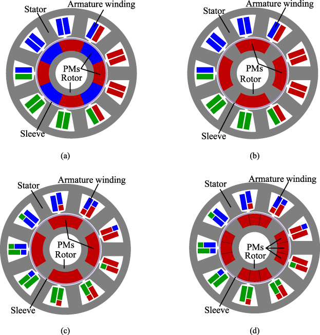
Cross-section of 9-slot/8-pole machines. (a) Conventional SPM machine with double-layer winding (SPM). (b) Conventional CPM machine with double-layer winding (CPM1-1). (c) Proposed CPM machine with optimized six-layer winding (CPM1-2). (d) Proposed Halbach PMs array CPM machine with optimized six-layer winding (CPM2-2).

Rotor configurations and permanent magnet magnetization direction. (a) SPM. (b) CPM1. (c) CPM2.
All the investigated machines have the same geometry size, turns per phase, and phase current. All the analyzed machines have been optimized by finite element method (FEM). Optimal selection is the tradeoff between average torque and torque ripple. The main design parameters are given in Table 1.
The SPM machine adopts the full PM-arc, and the PM-arc ratio 𝛼
p
in the CPM machines is defined as
Specifications of the 9-slot/8-pole machine
The CPM machine is a machine in which a set of PMs with the same polarity are replaced by iron core. The even-order harmonics appear in the air-gap flux density due to the missing of a set of PMs with the same polarity. The even-order harmonics cannot be counteracted in the phase-induced back-EMFs in the machines having three back-EMF phasors belonging to one phase for one unit machine [10]. The even-order harmonics can result in high torque ripple. Therefore, the key of improving torque performances is to suppress even-order harmonics in phase back-EMFs. In order to suppress the even-order harmonics in phase back-EMFs, the optimized six-layer winding is employed and the principle of suppressing the even-order harmonics in back-EMFs by optimized six-layer winding is explained in the following part. There will be a slight torque sacrifice when adopting multilayer winding. Hence, in order to compensate output torque, the Halbach PMs array are adopted.
According to the number of slots and the order of harmonics, there are some harmonics whose winding factors are the same as the winding factor of the vth harmonic. The order is calculated according to the following relationship (k is an integer)
The main harmonic is the harmonic of order 𝜈 = p. When v = p, it can be expressed by the following relationship:
The correspondence between stator magnetic motive force (MMF) and rotor MMF of 9-slot/8-pole machine in one mechanical period will be given in Table 2, where v ′ (stator) is the order of sub-harmonic which has the same winding factor as the corresponding order of v (stator). The order of these harmonics can be calculated by (2). As expressed in (2), for 9-slot/8-pole machine, the 1st, 8th, 28th, and 44th harmonics have the same winding factor; the 2nd, 16th, 20th, and 52nd harmonics have the same winding factor; the 4th, 32nd, and 40th harmonics have the same winding factor. Therefore, it is useful to reduce the winding factors of the 8th, 28th, and 44th harmonics through reducing the winding factor of the 1st harmonic. Obviously, it is also useful to reduce the winding factors of the 16th, 20th, and 52nd harmonics through reducing the winding factor of the 2nd harmonic. It is worth noting that it is impossible to reduce the 32nd and 40th harmonics amplitude without a corresponding reduction of the amplitude of the main harmonic (4th), which is an inappropriate choice for torque production. It is also shown that the 3rd torque harmonic is mainly due to the 8th and 16th MMF harmonics (i.e., the 2nd and 4th MMF harmonics with respect to the main harmonic of order 𝜈 = p = 4). Rearranging the winding of the machine, it is possible to reduce the winding factors of the 8th, 16th, 20th, and 28th harmonics, thus the torque ripple.
Correspondence between stator MMF and rotor MMF of 9-slot/8-pole machine
Recently, in order to improve the harmonic content of winding MMF, attention has been paid to the adoption of FSCW with more than two layers [21]. The star of slots was widely used to analyze the FSCW PM machine with different types of windings [22,23].
Figure 3(a) shows the star of slots of a double-layer winding. When the four-layer and six-layer windings have to be designed, the sectors are doubled and tripled. As shown in Fig. 3(b), the second set of sectors is shifted on the star of slots by an angle 𝛼 sh4; As shown in Fig. 3(c), the third sectors is shifted reversely on the star of slots by an angle 𝛼 sh6. In order to design a balanced and symmetrical winding, the 𝛼 sh6 should be equal to 𝛼 sh4 when six-layer winding is considered.
The coil throw y
q
is computed as
The machine periodicity t is defined as the greatest common divisor (GCD) between the number of slots and the pole pairs
The number of spokes in the star of slots is Q∕t. The angle between two spokes 𝛼
ph
is computed as
(1) Q∕T = even.
In order to obtain the maximum distribution factor for the main harmonic order, the shift angle is equal to the angle between two spokes, i.e., 𝛼 sh4 = 𝛼 ph [22].
(2) Q∕T = odd.
In this case, it is possible to shift the sectors in two different ways. The first way is that the shift angle is equal to the angle between two spokes, i.e., 𝛼 sh4 = 𝛼 ph . The second way is that the shift angle is equal to half the angle between two spokes, i.e., 𝛼 sh4 = 𝛼 ph ∕2. In the second way, there is a higher distribution factor obtained for the main harmonic order since the spokes corresponding to the coils connected in series are closer with respect to the first way [22]. Considering the main harmonic winding factor, the second way is chosen in this paper.
In the 9-slot/8-pole CPM machine, the even-order harmonics cannot be canceled due to three back-EMF phasors. Based on the star of slots in Fig. 3(a), the even-order harmonics in the phase back-EMFs cannot be canceled. This is due to the fact that the even-order harmonics induced in phasor 1 belonging to the positive sector cannot be canceled by phasors 2 and 9 belonging to the negative sector. As shown in Fig. 3(b), the number of sectors for each phase is doubled compared with the double-layer winding. As shown in Fig. 3(c), the number of sectors for each phase is tripled compared with the double-layer winding. The positive sectors of phase A is composed of A+, A + +, and A + ++, and the negative sectors of phase A is composed as A−, A−−, and A −−−. The A+ and A− are defined as the first set of sectors of phase A, denoted by W1 winding; the second set of sectors of phase A is composed of A + + and A −−, denoted by W2 winding; the third set of sectors of phase A is composed of A + ++ and A−−−, denoted by W3 winding. The cancelation principle of all the even-order harmonics can be explained by the star of resultant back-EMF.
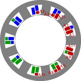
In order to suppress the even-order harmonics in back-EMFs greatly, the optimized six-layer winding is employed and the principle is explained as follows. First, according to the star of slots for the main harmonic in Fig. 3(c), the star of slots for the 2nd harmonic is drawn in Fig. 4. The red spokes are belong to phase A. Star of resultant back-EMF of W1, W2, and W3 for the 2nd harmonic is shown in Fig. 5. The suppression principle of harmonics can be explained by the star of resultant back-EMF. Adjusting the number of conductors, the stator winding can be rearranged so that the 2nd harmonic can be completely canceled. Meanwhile, the 1st is also suppressed greatly. It is highlighted that the coils have different numbers of conductors, i.e., A3+, A3−, A8+, A8−: n c1; A2+, A2−, A9+, A9−: n c2; A1+, A1−: n c3 (“+” is the positive polarity, “−” is the negative polarity, “n c1, n c2, n c3” is the number of conductors). To achieve such an optimized six-layer winding, the relationship n c2 = 2n c1 and n c3 = (2cos20° +4cos80°) n c1 ≈ 2.574n c1 must be satisfied. In the optimized six-layer winding, n c1 = 7, n c2 = 14, n c3 = 18. For comparison, the number of turns per coil is 20 in the double-layer winding. The total number of turns in the two windings is the same, i.e., 180. This means the same electrical loads. Although there are some differences of two windings, the comparison is fair by considering the same electrical loads.

Star of slots of 9-slot/8-pole three-phase machine. (a) Double-layer winding. (b) Four-layer winding with 𝛼 ph4 = 𝛼 ph ∕2 = 20°. (c) Six-layer winding with 𝛼 ph6 = 𝛼 ph4 = 𝛼 ph ∕2 = 20°.

Star of slots of 9-slot/8-pole three-phase machine for the second harmonic.

Star of resultant back-EMFs of W1, W2 and W3 for the second harmonic (phase A).
Winding factors of 9-slot/8-pole machine
Next, the winding factors of the double-layer winding and proposed optimized six-layer winding will be given. From the star of slots, the distribution factor of the winding k d can be computed by the classical theory. Considering the pitch factor k p depending on the actual coil throw y q , the winding factor is computed as k w = k p ⋅ k d .
The suppression principle of the even-order harmonics in back-EMFs can be explained by the star of resultant back-EMF. The harmonic winding factors of the 9-slot/8-pole machines with double-layer winding and optimized six-layer winding can be calculated based on the star of slots. According to the winding factors listed in Table 3, the 2nd harmonic is eliminated in optimized six-layer winding. It is worth noting that the 1st harmonic is also suppressed greatly. In other words, the 2nd harmonic content in back-EMFs is reduced by 91% for the 9-slot/8-pole machine with the optimized six-layer winding. Meanwhile, the 4th harmonic content in back-EMFs is eliminated.
In order to explain the proposed winding clearly, the layout of the coils of optimized six-layer winding is shown in Fig. 6. For the practical realization of the winding, the two or three coils can be merged so that only one coil is realized and the winding is simplified. Considering such a simplification in all, the winding yields some slots with three-layers and others with four-layers. Such simplification does not produce any appreciable modification of the machine performances and characteristics but a manufacturing simplification [22]. Obviously, the winding configuration is more complex than that of conventional one. However, it has greater effect on the reduction of torque ripple than conventional CPM machines.
Layout of coils of optimized six-layer winding (only phase A is shown).
The main harmonic of winding harmonic is related to the torque production. As shown in Table 3, the main harmonic of winding factor of the double-layer winding and optimized six-layer winding is 0.9452 and 0.9033, respectively. There will be a slight reduction of main harmonic back-EMF due to the reduction of main harmonic of winding factor, resulting in sightly lower torque production. Therefore, the Halbach PMs array are adopted to compensate the output torque. Hence, since the optimized six-layer winding can reduce most torque harmonics and the Halbach PMs array can enhance the torque density, the proposed CPM machine can guarantee the torque density and offer high PM utilization ratio with great reduction of on-load torque ripple simultaneously.
The software used for the numerical calculations is ANSYS Maxwell, which is commercial available software and has been widely used in the analysis of PM motor. The 2D FEM geometries of the four models have been given in Fig. 1 and the difference from each other has been discussed in detail in Section 2.
The normal air-gap flux density under open-circuit is shown in Fig. 7(a), while their harmonics are given in Fig. 7(b). Meanwhile, the tangential air-gap flux density components are given in Fig. 8(a), while their harmonics are shown in Fig. 8(b). The air-gap flux density of the CPM1-1 is not shown as its rotor is the same as the CPM1-2. As shown in Fig. 7(b) and Fig. 8(b), it can be clearly seen that the even-order (especially the 2nd and 4th) harmonics appear in CPM1-2 and CPM2-2 machines because the PMs on the rotor are the same polarity. As shown in Fig. 7(b), compared with CPM1-2, the normal air-gap flux density amplitudes of the 2nd and 4th harmonics are reduced by 78.7% and 67.8% in CPM2-2, respectively. However, compared with CPM1-2, the fundamental normal air-gap flux density in CPM2-2 is increased due to the Halbach PMs array. As shown in Fig. 8(b), compared with CPM1-2, the tangential air-gap flux density amplitudes of the 2nd and 4th harmonics are reduced by 86.7% and 46.4% in CPM2-2, respectively. However, compared with CPM1-2, the fundamental tangential air-gap flux density in CPM2-2 is increased. The fundamental normal and tangential air-gap flux density for the CPM machine is not reduced proportionally with the decrease of the amount of PM. This is because the CPM machine offers high PM utilization ratio. From Fig. 7(b) and Fig. 8(b), it can be seen that the CPM2-2 machine has the largest fundamental air-gap flux density in these machines due to Halbach PMs array. This is consistent with previous theoretical analysis of Halbach PMs array in Section 3. It can be seen that the 2nd and 4th harmonics in both normal flux density and tangential flux density are greatly reduced. Compared with normal air-gap flux density component, the amplitude of tangential air-gap flux density is low.

Normal air-gap flux density under open-circuit. (a) Waveforms. (b) Harmonics.
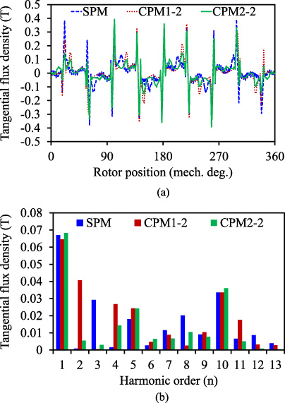
Tangential air-gap flux density under open-circuit. (a) Waveforms. (b) Harmonics.
The comparison of the magnetic normal flux densities resulting from each of three rotor configurations (as shown in the Fig. 2) is given in Fig. 9(a), while their harmonics are shown in Fig. 9(b). Meanwhile, the comparison of the magnetic tangential flux densities resulting from each of the rotor configurations (as shown in the Fig. 2) is given in Fig. 10(a), while their harmonics are shown in Fig. 10(b). As shown in Fig. 9(b) and Fig. 10(b), CPM1 and CPM2 rotor configurations contain even-order (especially the 2nd and 4th) harmonics because the PMs on the rotor are the same polarity. In order to observe the strongly non-symmetrical magnetic flux density produced with the configurations CPM1 and CPM2 clearly, the harmonics of them have been separately presented in Fig. 9(c) and Fig. 10(c). From Fig. 9(c), compared with CPM1, the amplitudes of the 2nd and 4th normal air-gap flux density harmonics are reduced by 80.0% and 32.7% in CPM2, respectively. However, compared with CPM1, CPM2 offers higher fundamental normal air-gap flux density due to the Halbach PMs array. From Fig. 10(c), the amplitudes of the 2nd and 4th tangential air-gap flux density harmonics are reduced by 79.8% and 57.5% in CPM2 compared with those of CPM1, respectively. However, compared with CPM1, the CPM2 offers higher fundamental tangential air-gap flux density because of Halbach PMs array. It can be observed that the 2nd and 4th harmonics in both normal flux density and tangential flux density are greatly reduced. The amplitude of tangential air-gap flux density is low compared with normal air-gap flux density component.
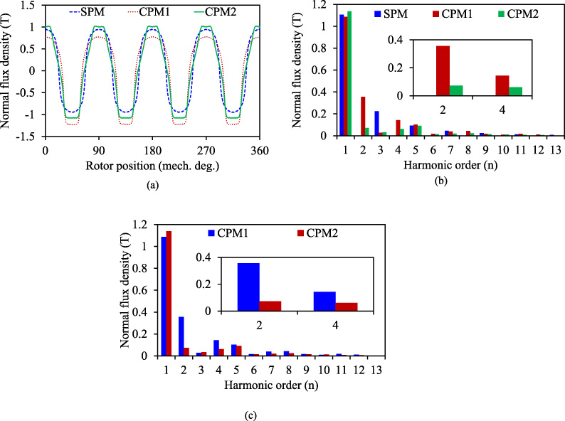
Normal air-gap flux density of these rotor configurations. (a) Waveforms. (b) Harmonics. (c) Harmonics (CPM1 and CPM2).
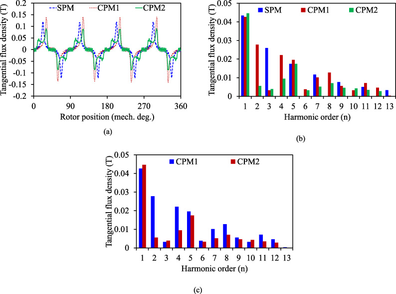
Tangential air-gap flux density of these rotor configurations. (a) Waveforms. (b) Harmonics. (c) Harmonics (CPM1 and CPM2).
Figures 11(a) and (b) show the back-EMF waveforms and the harmonic contents of the analyzed machines, respectively. It can be seen that the SPM machine has the largest main harmonic back-EMF due to more PM volume. As respected, compared with CPM1-1, there is a slight reduction of main harmonic back-EMF in CPM1-2. This is due to that there is a slight reduction of winding factor of main harmonic in optimized six-layer winding when compared with double-layer winding, as shown in Table 3. As respected, compared with CPM1-2, there is an improvement of main harmonic back-EMF in CPM2-2 due to Halbach PMs array. It can be seen that the Halbach PMs array can have higher main harmonic back-EMF compared to conventional PMs array. This is why CPM2-2 can have almost the same main harmonic back-EMF as CPM1-1. This is consistent with the previous theoretical analysis in Section 3.
In order to observe the suppression effect of the even-order harmonics in back-EMFs clearly, the amplitude of some harmonics in back-EMFs are listed in Table 4. Compared with CPM1-1, the amplitude of the 2nd and 4th harmonics in CPM2-2 are reduced by 97% and 99%, respectively. And it is approximately consistent with previous theoretical analysis in Section 3. In addition, the amplitude of the main harmonic in CPM2-2 is almost the same as CPM1-1. This is also consistent with previous theoretical analysis Section 3.

Phase back-EMFs of the analyzed machines. (a) Waveforms. (b) Harmonics.
Harmonics in back-EMFs of these machines
The cogging torque which is generated by the interaction between PMs and opening slot of the stator is a potential source of torque ripple, vibration, and noise of the machine. It is a kind of pulsating torque and does not contribute to the average torque. The number of cogging torque period (N
cog
) in one mechanical period with the traditional SPM rotor was defined as [24]
The number of cogging torque period in one mechanical period with the CPM rotor was defined as
It can be concluded that the cogging torque period of SPM machine is doubled compared with the CPM machine. The cogging torque of the CPM1-1 is not shown as its rotor and stator are the same as the CPM1-2. The period of the 9-slot/8-pole SPM machine is distinguished with CPM machine. The difference between CPM1-2 and CPM2-2 machine is the PMs array. The cogging torque of the analyzed machines is shown in Fig. 12. It can be seen that the amplitude of cogging torque of the 9-slot/8-pole CPM1-2 machine is the largest. It also can be seen that the amplitude of cogging torque of the CPM2-2 machine is lower than that of the CPM1-2 due to Halbach PMs array.
The torque ripple T
ripple
is defined as
Figure 13(a) shows the variation of electromagnetic torque, while its harmonic components are shown in Fig. 13(b). As far as the torque ripple of CPM2-2 is concerned, the cogging torque ripple is the dominant contribution for CPM2-2. Compared with the CPM1-1, the CPM2-2 almost has the significant lower torque ripple and equal output torque with the same volume of PMs. Furthermore, it can be seen the torque ripple of CPM2-2 is the lowest in all machines. Figure 13(b) shows the main torque harmonic of CPM1-1 is the 3rd harmonic. This is due to the 2nd and 4th harmonics in the back-EMFs. Figure 13(b) also shows the main torque harmonic of CPM2-2 is the 9th harmonic while the main torque harmonic of CPM1-1 is the 3rd harmonic. The order of main torque ripple harmonic is changed from the 3rd to 9th. The frequency of torque ripple has increased. Meanwhile, the amplitude of torque ripple is reduced greatly in CPM2-2. Moreover, the 9th torque harmonic is mainly due to the 32nd and 40th harmonics in back-EMFs (i.e., the 8th and 10th harmonics with respect to the main harmonic of order 𝜈 = p = 4). This is due to the 32nd and 40th harmonics have the same winding factors as the 4th harmonic, which is consistent with the previous theoretical analysis in Section 3.

Variation of cogging torque with rotor position.

Torque characteristics of the analyzed machines. (a) Waveforms. (b) Harmonics.
The torque characteristics of these machines are listed in Table 5. It can be seen that the amplitude of cogging torque of the CPM1-2 machine is 0.566 Nm higher than that of the traditional SPM machine. It also can be seen that the amplitude of cogging torque of the CPM2-2 machine is 0.524 Nm lower than that of the CPM1-2 due to different PMs array. For the 3rd torque component, the CPM1-2 is reduced by 93.6% compared with CPM1-1 due to the reduction of the 2nd and 4th harmonics in the back-EMFs. Hence, compared with CPM1-1, the CPM1-2 offers lower torque ripple due to optimized six-layer winding. Although the proposed windings are obviously technologically difficult to be realized compared with conventional double-layer winding, the proposed winding can greatly reduce the even-order (2nd and 4th) harmonics in back-EMFs, resulting in low on-load torque ripple in CPM machines. Hence, the proposed winding configuration is valuable. Compared with the SPM, the CPM2-2 can maintain 96.0% output average torque with 70% amount of PM. Compared with CPM1-2, the CPM2-2 has higher output torque and lower torque ripple. Compared with the CPM1-1, the CPM2-2 almost has the equal output torque with the same volume of PMs. Furthermore, compared with the SPM machine, the PM utilization ratio ŋ m (average torque per PM volume) is increased effectively (37% for CPM1-1 and CPM2-2). For the 3rd torque component, the CPM2-2 is reduced by 97.8% compared with CPM1-1 due to the reduction of the 2nd and 4th harmonics in the back-EMFs. Thus, the torque ripple of the CPM2-2 is 0.7% lower than that of the SPM while 8.7% lower than the CPM1-1. It also can be seen that the torque ripple of CPM2-2 is 1.9% which is the lowest in all analyzed machines.
Torque characteristics of these machines
The novelty of this paper comes from two parts. First, an optimized six-layer winding is proposed to suppress the even-order harmonics of the phase back-EMFs, then reducing the torque harmonics and resulting in low torque ripple. Second, the Halbach PMs array are adopted in CPM machine to obtain a sinusoidal magnetic field and to improve torque density. Then, a novel CPM machine with optimized six-layer winding and Halbach PMs array is proposed, and the proposed motor offers low torque ripple and high PM utilization simultaneously. Finally, the theoretical analysis has been verified through finite element analysis.
Footnotes
Acknowledgements
This work was supported in part by the National Natural Science Foundation of China under Grant 51877098 and Grant 51707083, and in part by the Priority Academic Program Development of Jiangsu Higher Education Institutions.