
Abstract
Magnetorheological (MR) dampers are important devices for reducing and controlling vibration. Dynamic response time is one of the key factors that determines the control ability and application of the MR damper. Metal foam MR dampers are potentially superior to conventional dampers due to their low cost and fast response. The dynamic response time of metal foam MR dampers is distinct from conventional dampers. In this paper, the effects of different metal foam materials on the dynamic response time of metal foam dampers are studied. Three response time parameters were defined, and an experimental system including a DC motor, force sensor, damper, and time relay was designed to collect dynamic response time parameter values using metal foam Cu and Ni, respectively. The experimental results show that the response time of MR dampers is faster using Ni rather than Cu metal foam due to the different permeability of the materials. The magnetic resistance model and Ansys simulation further prove that magnetic flux density is the main contributor to the differences in response time.
Introduction
Magnetorheological (MR) fluid is a kind of smart material that micron magnetic particles disperse in carrier fluids, and its rheological characteristics can be changed dramatically by adjusting magnetic fields. MR fluid can transfer from a Newtonian fluid to a non-Newtonian fluid in a few milliseconds in the effect of magnetic field, and this transition is reversible. This characteristic is known as the MR effect [1–3]. Owing to this characteristic, MR fluids have been widely used in vehicle seat suspensions [4–8], civil engineering [9–13], vibration dampers [4,14–20], oil and medical [21,22]. Among all these applications, MR dampers are popular among researchers and engineer due to their easily controllable damping force and fast response time. Therefore, dynamic response time is one of the key factors that determines the performance and application of MR dampers.
The dynamic response time of MR fluid dampers is complex and is still not thoroughly understood. However, many experiments and simulations focus on the behavior of MR dampers. Lord Corporation proposed a 180 KN MR damper and found that the response time is less than 60 ms [23]. They claimed that the response time of MR devices not only depends on the properties of MR fluid, but also the coil resistance and drive electronics impedance. Fernando and Koo [23–25] employed triangle wave to study the response time of MR dampers. They found that the response time is irrelative to external currents. However, it depends on piston velocity and testing system flexibility. The response time decreased exponentially with increasing piston velocity and eventually converged to a constant value. Due to different experimental environment and MR dampers, the response time is also determined by the magnetic circuit design and power drive mode [15,26]. Guan [27] studied a large-scale MR damper at different velocities and currents by experiment and FEM analysis. They observed that the electromagnetic response is the predominant factor to determine the response time. The response time also depends on the eddy currents and is accelerated by reducing eddy currents. Four main factors that affect response time are summarized by Chooi and Oyadiji [28], which are external currents, shear rate, particle volume, and magnetic properties of magnetic particles. They found that the relative response time did not depend on shear rates, but the other three factors affect the response properties significantly. Huseyin and Gordaninejad [29] studied the influence of MR fluid at different working modes on the response time. They discovered that the electromagnetic parameters and valve geometry have a significant impact on response time. The rising-time ring structure of MR valves is longer than the falling time, and the response time of radial structure MR valves, regardless of the rising or falling time, is faster than that of the ring structure. Furthermore, according to investigations of the transient response of MR fluid, Ulicny and Golden [30] concluded that there is a critical magnetic field strength.
To sum up, the response time obtained by each scholar is not the same. One of the significant reasons for this disparity is the definition of the dynamic response time of MR dampers and the specific scope range. The time period from the initial state up to 95% of the maximum damping force is defined as the dynamic response time of MR fluid dampers by Koo [31]. According to this definition, they investigated a type of MR damper from Lord Corporation, and they obtained the response time of 25 ms. Zhu [28] proposed a current-driven method to study the response time of a disc-shaped MR damper, and the response time reached 90% of the maximum current as response time. Finally, they got the response time of the damper as only 2 ms. Milecki [32] used a voltage source-driven method to investigate the linear and rotational MR damper, and the response time was 30–180 ms. Soda [33] explored an MR damper made by themselves. It showed response time of 300--400 ms. Fernando and Koo [24,25] defined the response time is the time necessary to make the transition from the initial state to 63.2% of the final state, or one time constant.
The research on response time leads to many inconsistencies due to different experimental materials, testing systems, and devices, especially for the new structure of MR dampers such as foam-based MR dampers. The metal foam MR damper is a new type of MR damper based on metal foam [34]. The MR fluid contained in metal foam can reduce the cost and lengthen the life span of the damper. When the magnetic field is zero, the MR fluids are stored in the metal foam materials; once upon external currents, the MR fluid is drawn from the metal foam into the shear gap and produces the damping force. The dynamic response time of a metal foam Ni MR damper was investigated by Yao [35–37]. The response time was longer than the traditional dampers for the time delay MR fluid extracted from metal foam. Both the current and shear rate are critical to response time. However, the experimental material is also an important factor.
Consequently, this study first presents the materials and a prototype metal foam MR damper. In order to determine the influence of different metal foam materials on the performance of the developed metal foam MR damper, a home-made testing system was developed. The two different metal foam materials were used with different permeability while the other characteristics were the same. To further interpret the results obtained by experiments, an equivalent magnetic resistance model mathematically was established. The magnetic resistance of metal foam full with MR fluids is investigated. Finally, an Ansys simulation is presented to verify the conclusion of the experiments and calculations.
Materials
The MR fluid (MR fluid J01T) is provided by Chongqing Instrument Materials Institute., the viscosity is 0.8 Pa ⋅ s at is 20 °C when there is none of magnetic field, and the average diameter of the magnetic particle is approximate 1–5 μm. Figure 1 gives the relationship between magnetic field intensity and shear stress. When the magnetic field intensity is 0.5 T, the shear stress becomes stable, and the MR fluid reaches saturation at this point.
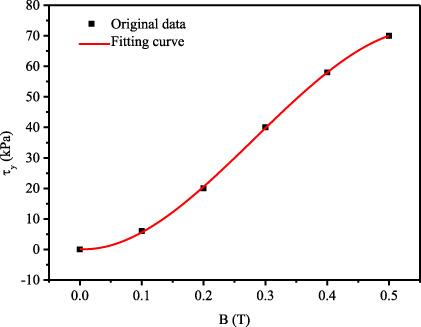
Magnetization curve of MR fluid.
The metal foam MR damper and two metal foam materials are from HGP Technology. Both the metal foam Cu and Ni are the same density of 0.26
Mechanical principle of metal foam MR damper
The mechanical principle of a metal foam MR damper is as follows. The metal foam facility to store the MR fluid when there is no external current. Once the external current is over a critical value, the magnetic force will overweight the gravity, surface tension and intermolecular interaction, MR fluid will be extracted from the metal foam into the shear gap, and produce the damping force, that is the MR effect.

Metal foam MR damper: Schematic of the damper: 1,7 end cover; 2 shear gap; 3 steel cylinder; 4 metal foam; 5 coil; 6 piston; 8,9 sheet copper; (b) Partly of the damper.
Figure 2 presents the structure of the metal foam MR damper. It is a two-end shear model MR damper. The metal foam (Cu or Ni) mentioned is adhered to the inside steel cylinder before filling with the MR fluid into the shear gap. To make sure the metal foam is full of MR fluid, according to the structure size of the metal foam MR damper, the volume of MR fluid is calculated in advance. It will stop filling with MR fluid until the surface of the metal foam begins weeping out. Note that it is better to rotate the steel cylinder when filling with the MR fluid to insure the metal foam is soaked evenly.
A test system was set up to evaluate the dynamic response time of the proposed damper based on different materials as shown in Fig. 3. The damper was fixed on a guide rail. A DC motor (model: YJ01) was used to make the damper move along the guide rail. The motor can be controlled by adjusted by a controller accompanied by a speed encoder. A load cell (model: NS-WL1) provided by Shanghai TM Automation Instruments Co., Ltd was used to obtain the damping force. A data acquisition (DAQ) system, including the DAQ card and PC with LabVIEW software, was employed to gather and process the test signal. A timer relay was designed to synchronize the start of the magnetic field, and it was also used to measure the starting point of the damping force change. According to the previous study [38], the magnetic flux density in the metal foam can be adjusted by controlling the current in the coil.

Test system of metal foam MR damper.

Test principle of the test system: (a) Response time of MR damper and sensor; (b) Response time of sensor.
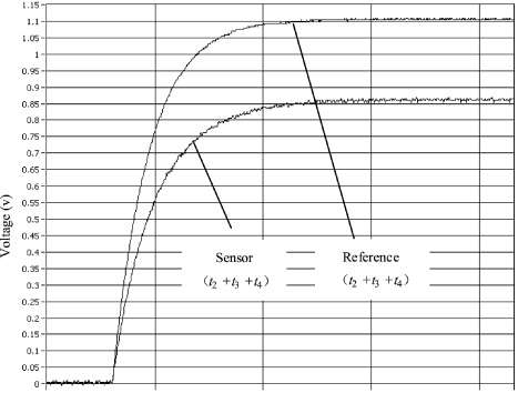
Response time of sensor.
The response time of MR fluids is in the order of milliseconds, so as to the porous foam metal MR damper. Two channels were used in the experiment. One channel is used to detect when the coil is energized, which includes the response time of the DAQ module and running of computer software. The other channel is used to detect when the damping force is generated, which includes the response time of the force sensor, the DQA module, and running of computer software. Considering that the response time of different channels may cause errors, the two channels were tested separately before the experiment. The results show that the signals detected by the two channels were less than 1 ms when the voltage signal is simultaneously supplied. Therefore, the influence of the response time of the two different channels on the porous foam metal MR damper can be ignored. Figure 4 gives the principle of the whole test system. t 1, t 2, t 3 and t 4 are the response time of MR damper, sensor, DAQ and running of computer software. According to Fig. 4(a), the difference of response time between channel 1 and channel 2 is the sum of the response time of the MR damper and the sensor, t 1 = (t 1 + t 2 + t 3 + t 4) − (t 2 + t 3 + t 4).
The response time of sensor t 2 can be obtained according to Fig. 4(b). The results are shown in Fig. 5, and a reference voltage is used. The reference voltage and sensor were controlled by the same switch, that is, the sensor and the reference voltage are started at the same time. The response time of the reference voltage channel includes the response time of DAQ module and running of computer with Labview. The sensor channel signal includes the response time of the sensor and the reference voltage. The difference between the two signals is the response of the force sensor. According to Fig. 5, the time required for the reference voltage signal and the sensor signal are almost equal from the initial state to the steady state. Therefore, the impact of the response time of the sensor is too small to ignore to obtain the response time of MR damper.
Dynamic response time parameters definition
The response time of the metal foam MR damper is much different from the conventional ones. As shown in Fig. 6, three time parameters, τdelay, τref and τresponse, were defined and the measure method detailed were discussed in reference [38]. τdelay is the time required from current on to damper force signal detected (during which MR fluids are drawn out from metal foam to shear gap); and τref is the time required for the damper force acquiring 63.2% of the steady damper force; furthermore, τresponse is defined as the total response time, from the current being turned on to the first steady state achieved.
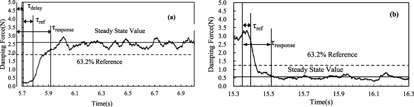
Typical defination of time parameters for metal foam MR damper: Damping force vs. rising time; (b) Damping force vs. falling time.
Figure 7 describes the time parameters of the rising process influenced by two kinds of metal foam, Cu and Ni, respectively. The shear rate is 10
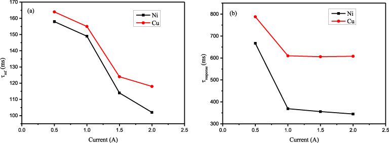
The comparison of response time τdelay in rising process of the two metallic foams, metal foam Cu and metal foam Ni, are also shown in Fig. 7(a). The τdelay of Ni is quicker than Cu. When the current is 1 A, the τdelay of Ni foam is 36 ms, and the τ delay of metallic Cu is 56 ms. The magnetic field lines in the magnetic circuit preferentially pass through the magnetically permeable material with a relatively high magnetic permeability. In the experiment, the relative permeability of metallic Ni in porous Ni is 4.33, the permeability of metallic Cu is 1, and the relative permeability of magnetorheological fluid is about 3.2. Since the relative permeability of porous Cu is less than that of MR fluids, the MR fluids firstly extract from the porous foam metal Cu and fill up the shear gap. When the relative permeability of the porous foam metal Ni is larger than that of the MR fluids, the magnetic field lines will first pass through metallic Ni until the magnetic field strength increases to another critical value, at this time, the metallic Ni is magnetized to a certain extent, the MR fluid is extracted. Therefore, the response time parameter τdelay is shorter than that of using porous foam Ni. However, when the external current is above 1.5 A, no matter which kind of metal foam material, the magnetic circuit in the metal foam MR damper has been saturated, and the shear gaps are filled with MR fluid, therefore, the response time τref of the metal foam Cu and Ni are not very much different. For example, when the current is 2 A, the τdelay of Ni foam is 27 ms, and the τdelay of Cu foam is 29 ms.

Influence of metal foams on response time parameters for rising process: (a) τ delay; (b) τ ref; (c) τ response. (Shear rate 10 mm/s.)
Influence of metal foams on response time parameters for falling process: (a) τ ref; (b) τ response. (Shear rate 10 mm/s.)
Figure 7 and Fig. 8 also describe the time parameters of the rising process and the falling process influenced by two kinds of metal foam, Cu foam and Ni foam, respectively. By comparing the two curves with solid symbols signified in Fig. 7 and Fig. 8, for both Cu and Ni in rising process and falling process, it shows that the larger the current, the smaller the response time, whatever the τdelay, τref or τresponse. In general, all the response time parameters decrease sharply when current increases from 0.5 A to 1.5 A compared with the period from 1.5 A to 2 A. Once the external magnetic field is applied, the magnetic particles in MR fluid are quickly magnetized and become chains with different lengths. The number of chains increases with the external current increment. Moreover, the larger the current, the longer the chain. When the chain reaches a certain amount, some of the chains are integrated into columns even to be a sheet. However, when the external current reaches 1.5 A, the magnetic particles are already saturated, and nearly none of the moveable particles remain. Therefore, the response time parameters decrease slowly and finally become a constant value, even increasing the external current.
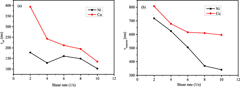
Figure 9 and Fig. 10 give the relationship between response time parameters and shear rate when external current is 1 A. The values of Cu are higher than that of Ni for all the response time parameters. The values of response time parameters values decrease with increasing the shear rates. The values of τdelay and τref decrease dramatically when shear rate change from 2/s to 6/s. Given the same current, the faster the shear rate, the more magnetic particle to move freely. Therefore, the more chain structures and the stronger the MR effect. Moreover, the damping force changes faster. Therefore, the quickly the response time.
From all the above mentioned, the response time of metal foam dampers largely depends on the magnetic field intensity. The magnetic flux density in the damper is discussed by calculation and Ansys in the next section.

Influence of metal foams on response time parameters for rising process (Current 1 A): τ delay; (b) τ ref; (c) τ response.
Influence of metal foams on response time parameters for falling process (Current 1 A): (a) τ ref; (b) τ response.
Calculation of magnetic flux density
In order to verify this phenomenon, the equivalent magnetic resistance models of porous metal foam MR dampers were further calculated. Figure 11 illustrates the equivalent magnetic resistance of metal foam filled with MR fluid. According to the model presented in Fig. 11, the equivalent magnetic resistance can be calculated as follows:
Since the magnetoresistance of the magnetorheological fluid is in parallel with the magnetic resistance of the porous foam metal, therefore
The magnetic resistance usually can be calculated by
Here, the porosities of the porous foam Cu and Ni are 85% and 95%, respectively. Hence, according to Eqs (2) and (3), and the
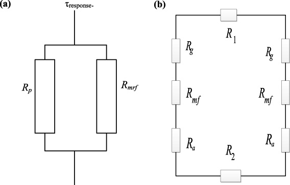
Equivalent magnetic resistance model of porous metal foam MR damper: Equivalent magnetic resistance; (b) model of equivalent magnetic resistance.
Here, the effective area of the magnetic circuit is 2.388 ×10⁻³ m2, N is the numbers of turns, N = 1635. According to the magnetic circuit Ohm’s law, the relationships between currents and the magnetic flux density in metal foam MR damper as follows.
Metal foam Cu:
According to Eqs (4) and (5), we can determine that the magnetic induction intensity in metal foam Cu MR damper is smaller than that of Ni if the current is the same. Therefore, under the same conditions, the volume MR fluid drawn out from Ni is more than that of Cu. Hence, the response time of metal foam Ni is quicker than that of Cu, which is the same as the experimental results.
Moreover, magnetic flux density in the shear gap is investigated by Ansys 13.0 software. Figure 12 gives the magnetic circuit structure of metal foam MR damper. And the magnetic simulation by Ansys is displayed as Fig. 13. View from Fig. 13(b), the maximum magnetic flux density in the shear gap is 1435.7 mT when the current is 2 A.
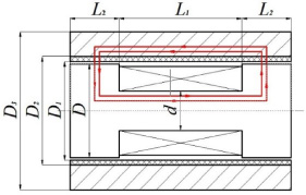
Magnetic circuit structure of porous metal foam MR damper.
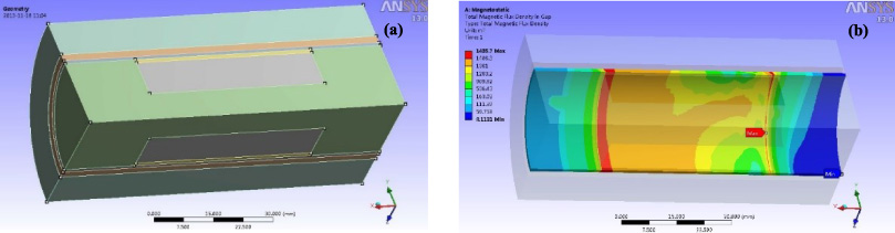
Magnetic simulation of metal foam MR damper: (a) 3D model (b) Magnetic flux density in shear gap of Ni foam based MR damper (I = 2 A).
The magnetic flux density in the shear gap of the metal foam MR damper with different metal foam materials is illustrated in Fig. 14. The magnetic flux density in the shear gap increases because of the metal foam materials. And the magnetic flux density in the shear gap is similar to increasing the current. When the external current changes from 0 A to 1.5 A, the magnetic flux density increases quickly whatever kind of metal foam material of the MR damper. However, it tends to be a constant value when currents increase from 1.5 A to 2 A owing to the magnetic saturation. Furthermore, according to the equation, magnetic field density and magnetic permeability are positively correlated. Nevertheless, due to the permeability of metal Ni is larger than that of metal Cu, thus the magnetic flux density of metal foam Ni MR damper is larger than that of Cu under the same conditions. At the same time, according to Fig. 14, the magnetic flux density of the two metal foam materials is not much different. This is mainly because the difference in permeability between the two foamed metal materials is small.
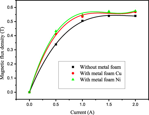
Magnetic flux density in shear gap with different metal foam (shear gap = 1 mm).
This paper investigated the influence of two kinds of metal foam, namely, Cu and Ni, on the dynamic response time of metal foam MR dampers. Three response time parameters, including τ delay, τ ref and τ response, were used in the experiment and are discussed. The results show that magnetic field intensity is the most important factor before the saturation of MR fluids for the three dynamic response time parameters for both the metal foam Cu and metal foam Ni. The response time sharply decreases when the external current can adjust from 0.5 A to 1.5 A due to the gathered magnetized particles in the MR fluid. This phenomenon further verifies that the metal foam MR damper can be controlled by the external magnetic current no matter which material. The rising time of Cu metal foam MR damper is about 2.5 times faster than that of Ni, and the falling time is 1.7 times quicker than Ni metal foam MR damper. Furthermore, by comparing metal foam Cu with metal foam Ni by calculation and Ansys simulation, this phenomenon maybe results that the permeability of Cu is 1.5 times smaller than that of Ni. These results further improve the research of dynamic response time and figure out the working mechanism of metal foam MR dampers. Moreover, it also gives a guideline to optimize structural design of MR dampers, and widen the engineering application of MR fluids. In the future, the rheological properties of MR fluid in metal foams will be furtherly studied to figure out the mechanism of the response time.
Footnotes
Acknowledgements
This work is partially supported by the National Natural Science Foundation of China (51605061), Chongqing Research Program of Basic Research and Frontier Technology (cstc2017jcyjAX0183), Science and Technology Research Project of Chongqing Municipal Education Committee (KJ1500627), Startup Project of Doctor Scientific Research (2016-56-04), School Projects of Chongqing Technology and Business University (1552003), and Open Grant of Chongqing Engineering Laboratory for Detection Control and Integrated System. The valuable comments and suggestions from the anonymous reviewer are very much appreciated.
Author information
Since 2014, she has been an Associate Professor with the School of Computer Science and Information Engineering at Chongqing Technology and Business University, Chongqing, China.
Her research interests include battery safety and reliability, prognostic methods on degradation-related machine, smart materials and vibration control.
He is the Founder and Director of the Center for Advanced Life Cycle Engineering, University of Maryland, College Park, MD, USA, which is funded by over 150 of the world’s leading electronics companies at more than US6M/year. He is also a Chair Professor of mechanical engineering and a Professor of applied mathematics, statistics, and scientific computation with the University of Maryland. He has written over 20 books, 400 technical articles, and has eight patents.
He has also served on three U.S. National Academy of Science studies, two U.S. Congressional investigations in automotive safety, and as an expert to the U.S. Food and Drug Administration. He is a Professional Engineer, a Fellow of the American Society of Mechanical Engineers, a Fellow of the Society of Automotive Engineers, and a Fellow of the International Microelectronics Assembly and Packaging Society. He is the Editor-in-Chief of the IEEE ACCESS, and served as the Chief Editor of the IEEE TRANSACTIONS ON RELIABILITY for nine years and the Chief Editor for Microelectronics Reliability for 16 years.