
Abstract
In this paper, one kind of U-shape permanent magnet embedded salient pole wind generator is proposed. The permanent magnet is divided into three sections to form a U-shaped structure and inserted into the salient pole in the generator. The size of the PM near the side frame is small, therefore, there is sufficient PM location modification space in the salient pole. Some flux-barriers are set in the upper core of the salient pole, which can reduce the q-axis inductance, and ultimately increases the generator maximum output power. To evaluate the generator’s overall performance, some other important electromagnetic parameters such as the air-gap flux density, the output voltage, the cogging torque, the output power, and the demagnetization performance are all calculated and analyzed base on finite element method (FEM). All the above parameters are compared with that of one V-shape permanent magnet embedded salient pole wind generator. The analysis results show that, with the same volume of permanent magnet, the proposed U-shape permanent magnet embedded salient pole wind generator has higher power density than the V-shape permanent magnet embedded salient pole wind generator.
Introduction
Recent years, with the rapid development of offshore wind farm, the generator with high reliability is investigated and developed to reduce the maintenance cost. The interior permanent magnet (IPM) generator can protect the PMs better than surface-mounted ones in the humidity and salt spray environment. Therefore, it is adopted in some design plans. Some interior PM generators are investigated, such as the V-shape PM generator used in [1], and the permanent magnet embedded salient pole wind generator with tangential-type PM proposed and analyzed in [2,3]. However, there are still some problems that should be solved to improve the electromagnetic characteristics of these generators [4]: the generator’s output power is reduced because the q-axis inductance L q is larger than the d-axis inductance L d , the permanent magnet suffers irreversible demagnetization when the generator is operating under on-load condition, and so on. Some optimization works need to be applied to improve the generator characteristics, such as changing the magnetic pole structure [5,6], or using optimization algorithm to change the PM shape [7], etc.
Due to its high power density, high efficiency, and especially its high reluctance torque, IPM motors have attracted much attention. In [8], a novel IPM synchronous machine with multi-flux barriers is proposed to enhance the flux intensifying effect and reduce the PM demagnetization risk. An IPM machine with less rare-earth PM and better flux intensifying effect is investigated in [9]. The performance and parameters of four kinds of IPMs used for electrical vehicles are compared and investigated in [10]. The demagnetization performance of U-shape PM machine is investigated and the improved rotor geometries are proposed to strengthen the PM anti-demagnetization ability in [11]. However, due to these IPM machines are used as motors, and their rotor poles are not quite suitable for use as large-scale wind generator because of their rotor poles’ non-modularity and poor air-gap ventilation. An original flux intensifying V-shape PM embedded salient pole wind generator (called V-shape model in this paper) is proposed in [12]. For the salient pole is adopted, the generator rotor poles can be produced modularly and the air-gap ventilation is improved. By using this structure, the flux in the air-gap is intensified and hence the PM demagnetization risk is reduced. The V-shape model has its advantage in the field of wind generator, so its characteristic parameters investigation is meaningful for large-scale generator development. However, due to the variation of its air gap (d–q) axis inductances, there is negative reluctance power, so the maximum output power is lower than the electrical power.
In this paper, an improved U-shape PM embedded salient pole wind generator (called U-shape model in this paper) is proposed to improve the electromagnetic parameters of this kind generator. In each pole, the PM is divided into three parts and a few of flux barriers are added in the upper core of salient pole to reduce q-axis inductance. In U-shape model, the size of the two PM pieces near the salient pole side frame is much smaller than the salient pole, therefore, the PM location can be modified flexibly. This characteristic can enhance the flux-intensifying effect and increase the generator power density.
In this paper, the topologies U-shape model are introduced in Section 2. Its no-load magnetic field distributions, d- and q-axis magnetic flux path and inductances are analyzed by using the finite element method (FEM) in Section 3. Some important parameters, such as the air-gap flux densities, the output voltage, the cogging torque, the output power, and the demagnetization performance are all calculated and compared with that of VPMESPWG in Section 4. And last the conclusion is given in Section 5.
Structure of the U-shape model
Figure 1(a) shows the configuration of U-shape model. The PM in the rotor core is divided into three parts to form a U-shape. The rotor pole upper core is designed as non-concentric with the inner stator circle to yield sinusoidal waveform of output voltage. In the upper core, some flux-barriers are inserted in to modify the magnetic flux paths and optimize the inductance characteristic. The upper core of the pole boot is the main path of the quadrature magnetic flux, therefore, the flux barriers placed in the direction shown in Fig. 1 can effectively reduce the area of the quadrature magnetic path and the permeability of the quadrature magnetic path, so as to achieve the purpose of reducing the quadrature inductance. In theory, the larger the total width of flux barriers is, the more obvious the reduction of the cross-axis inductance is. However, in order to avoid the influence of flux barriers on the waveform of air gap magnetic density, the thickness of flux barriers in the circumference should not be too large. Therefore, in V-shape model, the flux barriers are divided into five parts, while in U-shape model they are divided into three parts. It is worth noting that in order to highlight the advantages of U-shape model, in this paper, the total thickness of V-shape model is larger than that of U-shape model. As a comparation, the topology of the original V-shape model is shown in Fig. 1(b). Since PM designs are the main focus of this paper, the stator configurations and the salient pole height of the two kinds of generators are maintained the same to allow evaluation of their differences in performances due to PM. The minimum rotor core side frame width of the two kind generators is also set to the same value. It should be point out that, the PM volume of U-shape model is just 94.4% of that in V-shape one, therefore, the former one has less cost of magnet material than that of the latter one. And the number and total width of the magnetic barriers of V-shape model is greater than that of U-shape model, therefore, when the other parameters of the two generators are exactly the same, the q-axis reluctance of the former is larger than that of the latter. The main parameters of the two generators are as listed in Table 1.
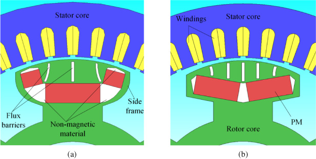
Configurations of the two types of generators. (a) U-shape model (b) V-shape model.
Main parameters of UPMESPWG and VPMESPWG
The relationship between the output power and L
d
and L
q
are as follows:
From this equation, it can be concluded that the total output power will be reduced if L q is larger than L d . In V-shape model, to improve the condition, a few of flux barriers are added in the upper core. But their effect is limited, because L q is still bigger than L d after the upper limited flux barriers are added in the magnetic pole upper core. Therefore, the generator’s maximum output power is still reduced. In this paper, U-shape model is proposed to solve this problem, in which not only the flux barriers but also the PMs can affect q-axis inductance, which will be explained in the following section.
Figure 2 shows the no-load magnetic field distributions of the two generators. As can be seen, there are some leakage fluxes in and between the magnetic poles, but they can be reduced by modifying the magnetic pole parameters. In order to reduce leakage fluxes in the side frame, the rotor core margin beside the non-magnetic material is narrow, which results in magnetic saturation in these areas. It can also be seen that, in the upper core, the magnetic saturation of U-shape model is more serious than that of V-shape model, but the opposite is true at bottom core area. That’s because the U-shape PM has greater tilt angle and change the flux path. By modifying the PM width and the tilt angle the magnetic saturation can be reduced in U-shape model.

No-load magnetic field distribution (a) U-shape model (b) V-shape model.
In V-shape model, due to the thick permanent magnets, the permeance along the d-axis is much lower than that along the q-axis which is mainly just an iron path. The simplest way to realize a rotor structure having L q < L d is by adding multiple layers of flux barriers along the q-axis flux path. By doing so, the flux barriers increase the effective air gap along the q-axis. Therefore, as a result, the permeance along q-axis can be reduced. However, it should be noted that the number and total width of the magnetic barriers must be controlled within a certain range, otherwise the harmonic of air gap magnetic density will increase dramatically.
In U-shape model, the d-axis and q-axis are defined along and perpendicular to the center of the PMs respectively. The path of the magnetic flux sourced by stator current is as illustrated in Fig. 3. As shown in the figure, fewer flux barriers than V-shape model are added in the q-axis path, and the U-shape PM is adopted. All of these can decrease the q-axis permeance, which ultimately leads to the fact that q-axis inductance is smaller than that of d-axis one after these modifications.

Magnetic flux paths of UPMESPWG (a) d-axis (b) q-axis.
Figure 4 shows the variations of L d and L q with the d-axis current I d and q-axis current I q in U-shape model and V-shape one. It is worth to mention that, the cross-coupling of I d and I q is taken into consideration in the calculation process and the number and total width of flux barriers in V-shape model are bigger than that in U-shape model as referred to earlier in this paper. It can be seen, in U-shape model, L d is significantly greater than L q under the same d- and q-axis currents, while the situation is just opposite in V-shape model. Therefore, in U-shape model, there is positive reluctance power, and ultimately its maximum output power is higher than the basic electromagnetic power. However, in V-shape model, the difference between L d and L q is negative, therefore, its maximum output power is reduced. It should be point out that, the d- and q-axis inductance can be optimized further by adjusting the thickness and positions of flux barriers and PMs in the flux path.
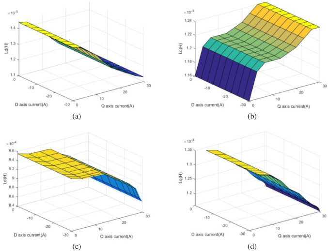
Inductance parameters (a) L d of U-shape model (b) L q of U-shape model (c) L d of V-shape model (d) L q of V-shape model.

The generator output power with power angle. (a) L d > L q in U-shape model (b) L d < L q in U-shape model.
It can also be obtained that, with the increase of I d , L d and L q in both of the two generators increase slightly. However, with the increase of I q , L q of U-shape model increases, but L q of V-shape model decreases. That’s because I q in U-shape model has demagnetization effect and it reduces the q-axis magnetic saturation.
In order to show more intuitively the influence of inductance parameters on the output power of the generator, the variation of the generator with power angle is compared in Fig. 5. In the figure, P represents the total output power, P1 represents the basic electromagnetic power, and P2 represents the additional electromagnetic power. Since the power angle of the generator is less than 90 degrees in normal operation, only the electromagnetic power in the range of 0–90 degrees is concerned. From the previous analysis, it can be seen that the influence of L d and L q on the output power can be divided into two kinds. In the case of L d > L q , the additional electromagnetic power is positive and it will increase the total output power, while in the case of L d < L q , the effect is opposite. In Fig. 5, two sets of U-shape model data, L d = 1.45 mH, L q = 1.16 mH and L d = 1.07 mH, L q = 1.16 mH, are selected for analysis. Under the same current, the inductances corresponding to V-shape model are L d = 0.95 mH, L q = 1.34 mH and L d = 0.89 mH and L q = 1.32 mH, respectively. Figure 5(a) shows that the additional electromagnetic power of U-shape model is positive, while that of V-shape L d < L q is negative. Although the basic electromagnetic power of U-shape model is slightly less than that of V-shape due to the increase of d-axis inductance, the total output power of U-shape model is larger than that of V-shape. In Fig. 5(b), the reluctance power of U-shape model and V-shape are all negative, but the absolute value of U-shape model is smaller, so its total output power is still larger than that of V-shape model. The above two sets of data represent the typical case of the influence of inductance of two generator models on output power. Therefore, it can be determined that the total output power of U-shape model is greater than that of V-shape under the same PM consumption.
Electromagnetic performance analysis
Flux density and output voltage
Figure 6(a) shows the no-load air-gap flux density distribution of the U-shape model and V-shape model. Figure 6(b) shows the corresponding fast Fourier transforms of the air-gap flux densities. As can be seen, the fundamental wave amplitude of U-shape model is 0.843 T, while the ones of V-shape model is 0.723 T. It shows that U-shape model can obtain larger air gap flux density with less permanent magnets than V-shape model, which indicates that it has better flux-intensifying ability. The total harmonic distortions (THD) of the two generators are 37% and 21% respectively, and they are mainly 3rd and 5th order harmonics which composed of the stator tooth and the flux-barrier harmonics. The U-shape model has higher harmonics, because its PM location and the rotor upper surface bias arc are failure to achieve optimal matching. It can be improved by optimizing the rotor upper surface bias arc.

Air-gap magnetic flux densities and phase voltage waveforms at no-load (a) Air-gap flux density waveforms (b) Air-gap flux density harmonic analysis (c) Phase voltage waveforms (d) Phase voltage harmonic analysis.
The effect of flux density harmonics on the voltage is weakened because of the application of distributed windings in the generators. Therefore, the THD of the output voltage is reduced significantly. As shown in Fig. 6(c), the fundamental wave amplitude of the phase voltage of U-shape model is 77.4 V, while that of the V-shape model is only 65.8 V. The advantage of adapting U-shape PM is obvious. The THD of the U-shape model output voltage is 14.9%, and that of the V-shape model is 8.1% as shown in Fig. 6(d). The phase voltage waveform can be optimized by adjusting the upper core surface bias arc in U-shape model.
Cogging torque determines the generator’s starting wind speed and affects the wind energy utilization. Figure 7 shows the cogging torque waveforms of the two type generators at different relative positions of stator and rotor. As shown in the figure, the cogging torque peak value of U-shape model is 0.37 N.m, which is higher than that of V-shape model (0.15 N.m). The main reason for this result is that the air-gap between the adjacent poles in U-shape model is wider than that of V-shape model. However, the cogging torque peak values of the two generators are all less than 1.5% of the rated torque, therefore, their effect can be ignored.
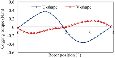
Cogging torque of U-shape model and V-shape model.
The demagnetization of the PM can be judged by its magnetic density distribution, that is, if the magnetic density of a region is less than the keen point of the PM magnetization curve, the region is an irreversible demagnetization region, otherwise it’s not. Therefore, in this section, the flux density distribution in the PM region is used to analyze the demagnetization performance. The demagnetization magnetic field produced by armature current is one of the main reasons for PM demagnetization. To assess the most serious irreversible demagnetization, the three-phase symmetrical sudden short-circuit currents of the two kinds of generator are calculated and their maximum values are used as armature currents to obtain the magnetic field distribution [13]. Figure 8 shows the current variations of the two kinds of generators after sudden short-circuit. It can be seen that, the maximum short-circuit current of the U-shape one is 11.29 times the rated current, while that of the V-shape one is 14.67 times.

The maximum sudden short-circuit current.
Because the PM keen point is affected by temperature, the demagnetizations under different temperatures are studied. The flux density distribution maps of the two kind generators under 140 °C and 170 °C are shown in Fig. 9(a) and (b) respectively. It can be seen that the PMs have very little demagnetization under 140 °C, and both the demagnetization areas are less than 0.3% of the whole PM area. When the PM temperature reaches to 170 °C, large area irreversible demagnetization exists in both PMs, and the V-shape model is more serious than the U-shape one. There are two reasons for this result: one is that the PM magnetic field of the V-shape model is almost opposite to the demagnetizing magnetic field, which is easy to cause demagnetization; the other reason is that the maximum current of the three-phase sudden short circuit of the V-shape model is larger than that of the U-shape one. From the results, it can be seen that the U-shape model is more anti-demagnetism than the V-shape one under the worst three-phase symmetrical short-circuit faults.
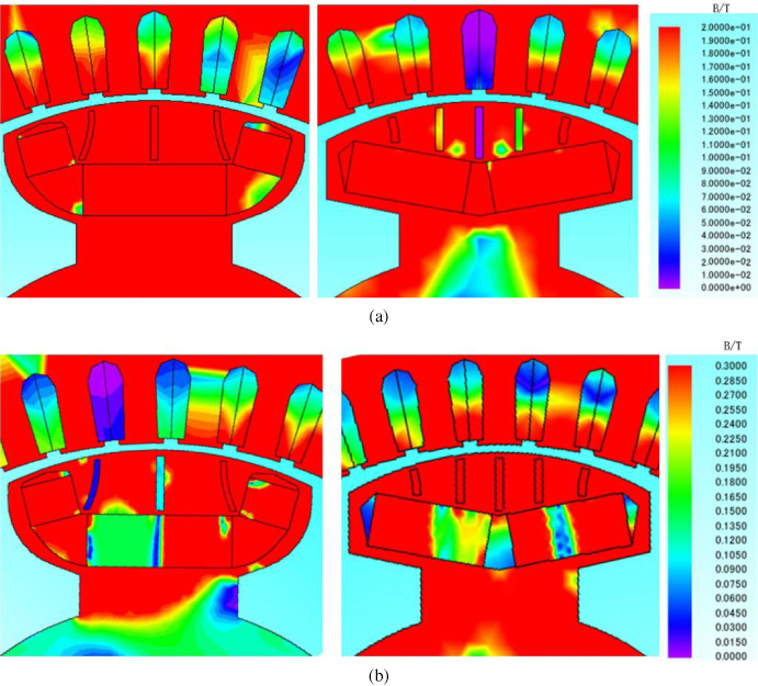
The maximum demagnetization in two generators. (a) U-shape model (b) V-shape model.
Interior PM generator is a good choice for offshore wind power, for its good PM protection and easy modular production. An improved generator model with U-shape embedded PM is proposed to improve the generator’s electromagnetic characteristics, especially the d- and q-axis inductance performance. Based on the analysis results, it has been demonstrated that: U-shape PMs bring an increase in d-axis inductance and a decrease in q-axis inductance, therefore the difference between them are reduced, and ultimately leads to an improvement of output power characteristic. U-shape PMs can also increase the utilization of PMs and less PMs will be used to produce the same output voltage. The cogging torque of proposed U-shape model is a little higher than that of the original V-shape model due to the increasing of air-gap width between two adjacent poles, but its influence on the total output torque can be neglected. The PMs of the U-shape model and V-shape one has little demagnetization under 140 °C when three-phase symmetrical sudden short-circuit fault occurs, while with the increase of temperature, the anti-demagnetization ability of U-shape one is more remarkable than that of V-shape.
The analysis results show that the proposed U-shape model has more advantages than the original V-shape model when they are used in the field of wind power. The work proposed in this paper provides a theoretical basis for U-shape permanent magnet embedded salient pole wind generator design in the development of offshore large PM wind generator.
Footnotes
Acknowledgements
This work was supported by the Fundamental Research Funds for the Central Universities (2019B14714, 2017B14114) and the National Natural Science Foundation of China (51507051).