
Abstract
Electromagnetic acoustic transducers (EMATs) have been widely applied in nondestructive testings and structural health monitoring. This paper proposes a flexible surface wave electromagnetic acoustic transducer (FSW-EMAT), which uses flexible rubber magnets instead of hard permanent magnets, in order to achieve the defects detection of steel pipe or other ferromagnetic structures with a certain surface curvature. Traditional EMATs mainly consist of three parts: magnet, coil and metal specimen to be tested. Permanent magnets or electromagnets are generally used to produce the strong magnetic flux density. However, the two kinds of magnets are not suitable for the defect detection of metal specimens with a certain curvature. The proposed FSW-EMAT in this paper adopts a flexible magnet, which is a mixture of rubber and iron powder and has strong flexibility to fit the bent specimen. The proposed FSW-EMAT can be easily applied in the testing of curved structural component and detect axial and circumferential defects by rotating the transducer.
Introduction
Ultrasonic guided wave testing is a new nondestructive testing method. The electromagnetic ultrasonic technology requires no coupling agent and has a low surface requirement on tested parts. Generally, the magnet of EMAT includes permanent magnet or electromagnet. These two kinds of magnets are both rigid, so the detection of curved surfaces is not particularly suitable. Several advanced research teams have made achievements in this respect currently. Liu et al. [1] proposed a new magnetostrictive patch transducer (MPT) and the developed MPTs array could generate pure L(0,2) mode, and had the potential to detect defects in pipes accurately. Wang et al. [2] provides a method to enhance the excitation efficiency of the torsional wave PPM EMAT array for pipe inspection by optimizing the number of elements of the array based on 3-D FEM. Cong et al. [3] proposed a new electromagnetic acoustic transducer (EMAT) design based on a permanent magnet chain to generate and receive longitudinal guided waves for pipe inspection. By changing the shape and arrangement of permanent magnets and coils, various types of guided wave modes can be produced in waveguides, which can be applied to many other fields. Such as pipes [4–7] and plates [8–11], and strands [12,13]. The surface wave is a special ultrasonic guided wave mode whose propagation depends on only one boundary, so it is suitable for defects detection of thick plates and thick-walled pipes. In semi-infinite isotropic materials, surface waves do not have dispersion problems and can propagate along the structure surface. Compared with other ultrasonic guided waves with diverse modes and dispersions, surface waves have significant advantages for near-surface defects detection [14,15].
The surface wave is a sound wave discovered by Rayleigh in the 1880s. White and Voltmer achieved a key breakthrough in surface wave technology [16]. Thompson et al. [17] established a theoretical model of electromagnetic ultrasonic surface waves and studied the transduction process of surface waves and plate waves in non-ferromagnetic materials. Then Thompson et al. [18] studied ferromagnetic materials and indicated that the magnetostrictive effect had an important influence on the energy exchange efficiency. The Lorenz force mechanism and magnetostrictive force mechanism were introduced and the electromagnetic ultrasonic guided wave technique was applied in the test of metal specimens. Masserey et al. [19] studied the relationship between the reflection and transmission coefficients as a function of the relative surface wave wavelength with respect to the depth of the near surface defects. Biryukov et al. [20] derived the wave equation of surface waves. In order to simplify the solution process, some items in the wave equation were omitted, so the solution only involves the influence of curvature on the surface wave in the direction of wave propagation. In summary, the design and optimization of EMAT have been extensively explored to provide theoretical supports for the application of surface acoustic wave EMAT on metal pipes.
Working principle of the FSW-EMAT.
This paper aims to develop a flexible surface wave EMAT (FSW-EMAT) for ferromagnetic pipe inspection and defect location. It has many unique advantages over permanent magnet EMAT. First of all, it can be applied in ferromagnetic pipes and other structures with a certain curvature. Second, conventional electromagnetic acoustic transducers generally use a permanent magnet to provide a bias magnetic field. Although the magnetism of permanent magnet is stronger on the ferromagnetic pipe, it is difficult to move the magnet due to its large attraction. It is easy to damage the transducer as well as pipe surface. Compared with traditional permanent magnets, the proposed FSW-EMAT in this paper has better mechanical properties. It is resistant to impact and not easy to be damaged. In addition, the proposed FSW-EMAT can also be used to detect defects on inner and outer walls along both axial and circumferential directions of the ferromagnetic pipeline.
The rest of the paper is organized as follows. Section 2 describes the configuration and working principle of the proposed FSW-EMAT. The characteristics of frequency response and acoustic field distribution of the proposed FSW-EMAT are discussed based on experimental results in Section 3. Section 4 compares the FSW-EMAT and the traditional permanent magnet EMAT based on simulation and experiments. Section 5 discussed the defects detection experiments on inner and outer walls along circumferential and axial directions of the FSW-EMAT. The conclusion is drawn in Section 6.
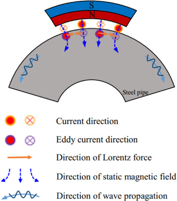
Magnetostrictive force should be considered in ferromagnetic pipe, but the direction of static magnetic field generated by the flexible magnet is perpendicular to the dynamic magnetic field by the coil. So the Lorenz force is much higher than the magnetostrictive force. The surface wave is mainly produced by the Lorenz force rather than the magnetostrictive force. So it produces the Lorenz force through the interaction between the induced eddy current and the external magnetic field on the surface of the specimen, thus producing surface wave on the surface of the specimen. The working principle of the proposed FSW-EMAT is shown in Fig. 1.
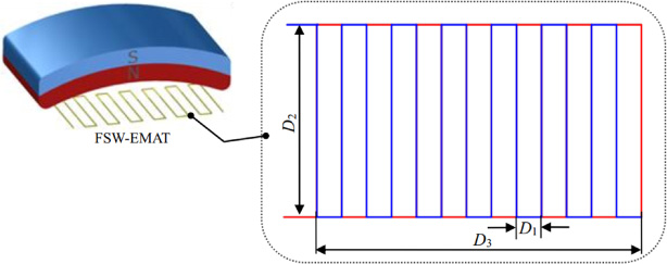
In order to excite and receive surface waves on a ferromagnetic pipe or other surface of a ferromagnetic specimen with a certain curvature, the flexible surface wave EMAT (Fig. 2) is proposed. The transducer consists of a flexible magnet and a meander-line coil and is called FSW-EMAT.
Configuration of the proposed FSW-EMAT
The magnet in FSW-EMAT is made of bonded ferrite magnetic powder and synthetic rubber. It is a flexible, elastic and twistable magnet made by extrusion, calendering, injection molding and other processes. The size of the flexible magnet is 40 mm × 25 mm × 10 mm.
The coil is a meander-line flexible printed circuit (FPC) coil with double layers. The size of the meander-line coil is shown in Fig. 2. The spatial periodicity of the meander coil was utilized to enhance the energy of the target wave mode by constructive interference phenomena [21,22]. Furthermore, the distance between the two adjacent annular wires D
1 is equal to half of the wavelength 𝜆 of the selected surface wave. In this paper, the velocity of surface wave c
p is about 3000 m/s, the spacing D
1 is chosen to be 3 mm and the corresponding theoretical center frequency, fc
, of surface wave in the steel pipe is 500 kHz according to Eq. ((1)).
Schematic diagram of experimental system utilizing a pair of proposed FSW-EMATs.
Frequency response characteristics of the FSW-EMAT.
Frequency response characteristics
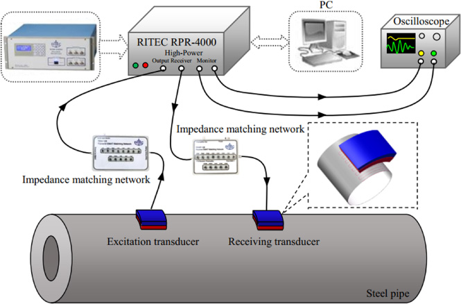
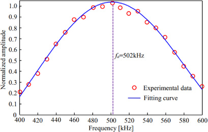
Schematic diagram of experimental system utilizing a pair of proposed FSW-EMATs is shown in Fig. 3. This pair of proposed FSW-EMATs are used for the excitation and reception of surface waves in the steel pipe by the pitch-catch approach. In the design of the transducer, the center frequency of the FSW-EMAT is determined by the spacing between adjacent wires of the coil. According to the working principle of FSW-EMAT, the center frequency of the designed transducer is 500 kHz. In order to verify the actual center frequency of the developed FSW-EMAT, the frequency response characteristic test of the transducer was carried out. Schematic diagram of experimental system utilizing FSW-EMAT as the excitation transducer is shown in Fig. 3. In this experimental system, a thick wall steel pipe with an outer diameter of 420 mm and a wall thickness of 30 mm was used as the test sample. The excitation frequency varied from 400 kHz to 600 kHz with an increment step of 10 kHz. The excitation signal is a 5-cycle sinusoidal signal modulated by Hanning window. Frequency response characteristics of the FSW-EMAT are shown in Fig. 4. The tested data are represented by red circles. The Gaussian first-order fitting curve shows that the actual center frequency of FSW-EMAT is 502 kHz, which is basically consistent with the theoretical center frequency of 500 kHz (the relative error is 0.4%).
Acoustic field distribution
The directivity experiment was carried out according to the transducer combination shown in Fig. 3 and the position of the receiving transducer was kept unchanged. Figure 5 gives schematic diagram of the acoustic field distribution testing system. As shown in Fig. 5, the excitation transducer was tested once at each interval of θ = 10° from 0° and recorded until 60°.
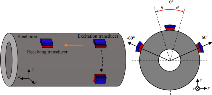
Schematic diagram of the acoustic field distribution testing system.
Each acquisition signal was recorded and extracted to obtain the direct wave signal (Fig. 6). According to the FSW-EMAT directivity experiment results shown in Fig. 6, the transducer only has a signal between −10° and 10° and the signal amplitude is maximized when the excitation and receiving transducers are on the same line. Therefore, the FSW-EMAT has good directivity and a relative long detection distance.
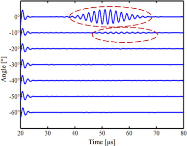
Received signals of the FSW-EMAT at different angles.
Comparison of working principles
The designed FSW-EMAT was used to test the pipe. The transducer can better fit the curved surface of the ferromagnetic pipe with a flexible magnet, whereas only partial surface of the permanent magnet can contact with the pipe. The working principle of these two EMATs is shown in Fig. 7.
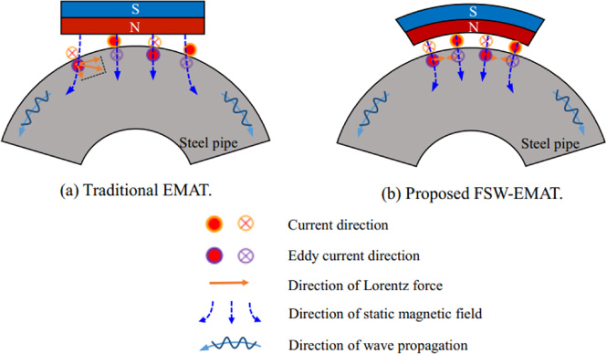
Working principle of these two EMATs.
According to the static magnetic field distribution shown in Fig. 7, for the FSW-EMAT, because the flexible magnet can be better fitted to pipe surface, the induced eddy produced by the coil on pipe surface is mainly affected by the radial magnetic field perpendicular to pipe surface produced by the flexible magnet. Figure 7(b) shows the working principle of a transducer utilizing a flexible magnet. The magnetic field produced by a flexible magnet acts on the induced eddy to produce Lorenz force along the tangent direction of pipe surface so as to stimulate the surface wave on pipe surface. For a traditional permanent magnet EMAT (Fig. 7(a)), the magnetic field produced by the permanent magnet is not completely perpendicular to pipe surface because the permanent magnet cannot be adapted to the bent pipe wall. The magnetic field provided by the permanent magnet acts on the induced eddy current on pipe surface to produce Lorenz force, which is parallel to the surface of the permanent magnet rather than in the tangential direction of the pipe. In fact, only Lorenz force produced in the tangential direction plays a role in the propagation process of surface wave along the surface, but the existence of the force in other directions will produce irregular radial alternating Lorenz force, thus interfering the signal.
Simulation analysis of static magnetic field
In order to compare the performances of the two transducers, the magnetic field distributions of the magnets on the tested specimen were simulated first and then the defects detection experiments were carried out with a pitch-catch transducer. The received signals of the FSW-EMAT and the traditional permanent magnet EMAT were compared.
Before the experiment, the model was constructed by COMSOL Multiphysics to simulate the magnetic field distribution of flexible magnet and permanent magnet on pipe surface. In the simulation, the size of the permanent magnet is 40 mm × 25 mm × 5 mm and the size of the flexible magnet is 40 mm × 25 mm × 10 mm. The residual magnetic flux densities of the two magnets are 140 mT. The pipe size is consistent with the size used in the experiment. The material of the pipe is steel. The outer diameter is 420 mm and the wall thickness is 30 mm. The magnetic flux density of the simulated pipe surface is shown in Fig. 8.
Bias static magnetic flux density distribution of the two EMATs.
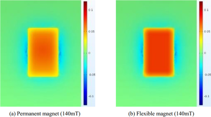
As shown in Fig. 8, under the same residual flux density, flexible magnets can produce a uniform and stronger magnetic field on the surface of the fitted ferromagnetic pipe compared with permanent magnet because flexible magnets can be better adapted to the bending pipe surface and produce a magnetic field perpendicular to pipe surface. The permanent magnet cannot be fitted to the wall of the pipe, so the magnetic field is not completely perpendicular to pipe surface, one of which points to the tangent direction of the arc of the pipe wall, which leads to the weakening of the magnetic field intensity on the pipe. And because the distance between the surface of the magnetic field and the surface of the pipe is different, the numerical value of each tangent magnetic field is different, so the distribution of the magnetic field on the surface of the pipe is not uniform. The distribution of the magnetic flux density on the surface of the specimen directly below the flexible magnet and the permanent magnet in FSW-EMAT and traditional EMAT is simulated and analyzed under the same total volume of the magnet. Figure 9 shows the simulation results of extracting magnetic flux density B sy perpendicular to the specimen surface. The results show that, compared with the static magnetic field provided by traditional permanent magnet, the B sy provided by flexible magnet is not only higher in amplitude than that provided by permanent magnet, but also much better in uniformity in the area covered by the magnet.
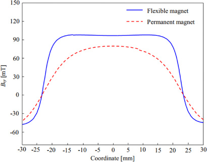
Distribution of B sy on the surface of the specimen below the two magnets (The residual flux density of flexible magnet and permanent magnet are both 140 mT).

Bias static magnetic flux density distribution of the two EMATs.
However, due to the difference in the characteristics of the magnet in practical application, the residual flux density in the two transducers used for comparison purpose cannot be guaranteed completely, so the residual magnetic flux density of the magnet is calculated according to the actual observed value of the magnetic flux density of the two magnets. The residual flux density of flexible magnet is set as 110 mT and the residual flux density of the permanent magnet is set as 140 mT. The simulation results are shown in Fig. 10. The magnetic field intensity of permanent magnet and flexible magnet placed on the surface of the pipe after the actual residual flux density is closer, but the magnetic field distribution of the flexible magnet on pipe surface is even more uniform. Figure 11 shows the simulation results of extracting magnetic flux density B sy perpendicular to the specimen surface. The results show that, compared with the static magnetic field provided by traditional permanent magnet, the B sy provided by flexible magnet still has a little higher amplitude than that provided by permanent magnet, and has better uniformity in the area covered by the magnet.
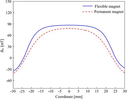
Distribution of B sy on the surface of the specimen below the two magnets (The residual flux density of flexible magnet and permanent magnet are 110 mT and 140 mT).
Schematic diagram of the axial notch defect testing system on outer wall of the steel pipe is shown in Fig. 12. Defect detection was performed on the conventional permanent magnet surface wave EMAT and FSW-EMAT, respectively. In the experiment, the receiving and excitation transducers were respectively replaced by permanent magnet surface wave EMAT and FSW-EMAT. The notch defect size is 25 mm × 1 mm × 1 mm. The outer diameter of the steel pipe is 420 mm and the pipe thickness is 30 mm. The distance between the excitation transducer and the receiving transducer is defined as L 1. The distance between the receiving transducer and the notch defect is defined as L 2. In the axial experimental of the two transducers, L 1 is chosen to be 100 mm and L 2 is chosen to be 90 mm. The red arrows represent the propagation path of surface waves.
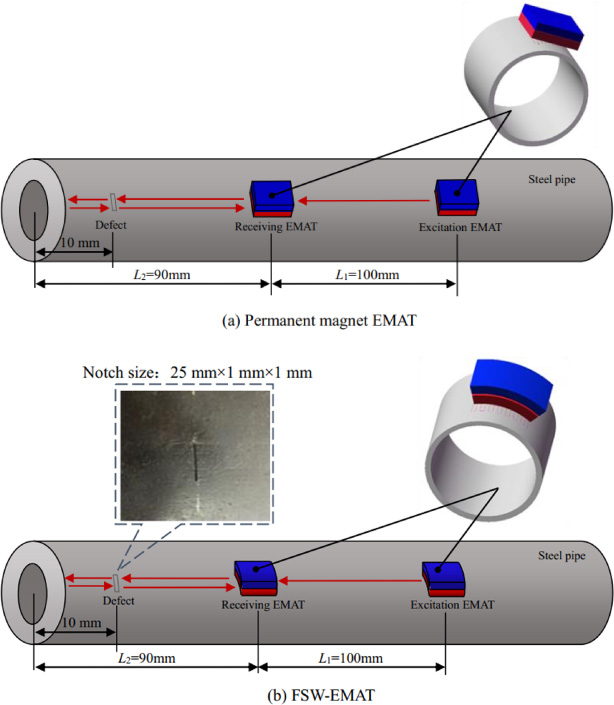
Schematic diagram of the axial notch defect testing system on outer wall of the steel pipe.
Figure 13 shows the original signal received by two kinds of EMAT axial defect detection and contrast experiments, which can determine two wave packets in the picture, one is the direct wave signal, and another is the defect echo signal. In addition, the direct amplitudes of the two received signals are 22.52 mV and 25.62 mV, respectively. The amplitudes of the defect echoes are 8.34 mV and 8.63 mV, respectively. The time-of-flight of the direct echoes and defect echoes of the FSW-EMAT is the same to that of the traditional permanent magnet surface wave EMAT. The amplitude of the signal is slightly larger than that of the permanent magnet EMAT. And the signal-to-noise ratio of the received signal of the FSW-EMAT in Fig. 11(b) is 9.6 dB which is better than that of 8.6 dB of the conventional surface wave EMAT in Fig. 11(a), as indicated by the simulation results, the magnetic field produced by flexible magnet is stronger and more uniform than that produced by permanent magnet in the direction perpendicular to the specimen surface, which will enhance the signal-to-noise ratio of the signal. The flexible magnet can better fit pipe surface, so the static direction of the magnetic field is vertical to pipe surface. Alternating Lorenz force is produced along the pipe to form surface wave. However, the traditional permanent magnet EMAT cannot be attached to pipe surface. Therefore, under the action of static magnetic field, it will produce irregular alternating Lorenz force and interfere the signal.

Received signals of the two transducers for testing the axial notch defect on outer wall of the steel pipe.
Schematic diagram of the defect detection experiment of the circumferential notch defect of outer wall of the pipe is shown in Fig. 14. The detection was performed on the conventional permanent magnet surface wave EMAT and FSW-EMAT, respectively. In the experiment, the receiving and excitation transducers were respectively replaced by a conventional permanent magnet surface wave EMAT and a FSW-EMAT. The notch defect size is 25 mm × 1 mm × 1 mm. The outer diameter of the steel pipe is 420 mm and the pipe thickness is 30 mm. The distance between the excitation transducer and the receiving transducer is defined as C 1. The distance between the receiving transducer and the notch defect is defined as C 2. In the circumferential experimental of the two transducers, C 1 is chosen to be 100 mm and C 2 is chosen to be 80 mm. The red arrows represent the propagation path of surface waves.
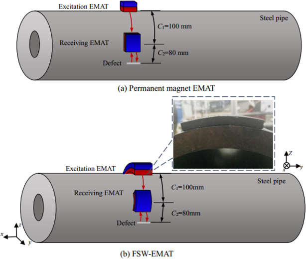
Schematic diagram of the detection test of the circumferential notch defect of outer wall of the pipe.
Figure 15 shows received signals of the two transducers for testing the circumferential notch defect on outer wall of the steel pipe. One of the two wave packets in Fig. 13 is a direct wave signal and the other is a defect echo signal. In addition, the direct wave amplitudes of the two received signals are respectively 36.38 mV and 35.89 mV and the defect echo amplitudes are respectively 11.89 mV and 10.25 mV. The amplitude and time-of-flight of the direct wave and the defect echo are basically the same, but it can be clearly seen from the comparison between the two figures that the signal-to-noise ratio of the received signal of the FSW-EMAT in Fig. 15(b) is 10.8 dB which is better than that of 9.7 dB of the traditional surface wave EMAT in Fig. 15(a). As we can see that the traditional permanent magnet EMAT has a worse connection to the pipe in the circumferential test, and the comparison of the signal-to-noise with the axial defect detection signal is lower. The FSW-EMAT has a higher signal-to-noise ratio in the comparison experiment because of its better consistency with the pipe and it has higher magnetic field and better uniformity in the direction perpendicular to the specimen surface.

Received signals of the two transducers for testing the circumferential notch defect on outer wall of the steel pipe.
Defect detection of outer wall of the pipe
In Sections 4.2.2 and 4.2.3, the designed FSW-EMAT can be well applied in the axial and circumferential defect detection of outer wall of the steel pipe and has a better effect than the permanent magnet surface wave EMAT. The defect inspection experiment was performed on inner wall of the steel pipe.
Defect detection of inner wall of the pipe
The defect detection method of pipe inner wall is basically the same as that of the pipe outer wall. The location of the axial and circumferential defects in the pipe were detected according to the same principle in the inner wall of the pipe according to the method in the upper section. The size of the notch defect is 25 mm × 1 mm × 1 mm.
Circumferential defect detection
Figure 16 is schematic diagram of the detection test of the circumferential notch defect of inner wall of the pipe. The interval between the excitation transducer and the receiving transducer is W 1 = 140 mm. The spacing between the notch axial defect and the receiving transducer is W 2 = 60 mm and the defect size is 25 mm × 1 mm × 1 mm. The outer diameter of the steel pipe is 420 mm and the wall thickness is 30 mm. The red arrow indicates the surface wave propagation path.
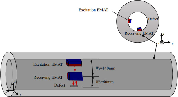
Schematic diagram of the detection test of the circumferential notch defect of inner wall of the pipe.
Figure 17 shows the circumferential notch defect detection and received signal of inner wall of the pipe. The direct wave path is W 1 = 140 mm and the propagation distance of defect echo is 260 mm. According to the time-of-flight method, the actual wave velocity, c, of the surface wave is calculated as: c = W 1∕Δt = 3111 m/s when the time-of-flight of the direct wave we chose from Fig. 15 is 45 μs. The propagation distance of defect echo calculated with the wave velocity is 264 mm when the time-of-flight of the defect echo wave chosen from Fig. 15 is 86 μs, which is close to the theoretical distance of 260 mm. Therefore, the transducer can well detect circumferential defects in inner wall of the pipe.
Received signal of the FSW-EMAT for testing the circumferential notch defect on inner wall of the steel pipe.
Figure 18 shows a schematic diagram of the detection method of axial notch defects in inner wall of a pipe. The interval between the excitation transducer and the receiving transducer is S 1 = 100 mm. The interval between axial notch defect and receiving transducer is S 2 = 50 mm and the defect size is 25 mm × 1 mm × 1 mm. The outer diameter of the tested steel pipe is 420 mm and the wall thickness is 30 mm. The red arrow represents the surface wave propagation path (including reflected echo path and end echo path).
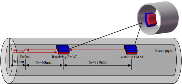
Schematic diagram of the axial notch defect testing system on inner wall of the steel pipe.
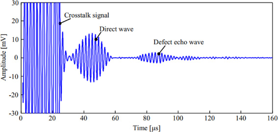
The received signal of the testing experiment of axial notch defect on inner wall of the pipe is shown in Fig. 19, which can be obtained by calculation. They are the crosstalk signals, the direct wave, the defect echo and the left end echo of the pipe from left to right. According to the time-of-flight method, the actual wave velocity, c, of the surface wave is calculated as: c = S 1∕Δt = 3056 m/s. when the time-of-flight of the direct wave Δt we chose from Fig. 19 is 36 μs. The propagation distance of defect echo is 235 mm when the time-of-flight of the defect echo wave we chose from Fig. 19 is 78 μs, which is close to the theoretical defect distance of 230 mm. The position of end echo is 296 mm when the time-of-flight of the left end echo wave we chose from Fig. 19 is 97 μs, which is close to the theoretical value of 290 mm. The results indicate that the FSW-EMAT can effectively detect the axial defects of inner wall of the pipe.

Received signals of the FSW-EMAT for testing the axial notch defect on inner wall of the steel pipe.
The experimental results indicate that the designed FSW-EMAT in this paper has a strong applicability. The transducer can detect the defects in the axial, circumferential, the inner and outer walls of the ferromagnetic pipes, such as steel pipes.
In the study, based on the Lorenz force mechanism, a flexible surface wave electromagnetic acoustic transducer (FSW-EMAT) composed of flexible magnets and meander coils is designed. The surface wave is excited on inner and outer surfaces of steel pipe and the defect detection of ferromagnetic specimens with a certain curvature is realized. Compared with traditional permanent magnet surface wave EMAT, the new FSW-EMAT had the following significant advantages.
Firstly, the proposed FSW-EMAT can effectively excite surface waves on the surface of steel pipes and detect defects on inner and outer walls and along axial and circumferential directions.
Secondly, the actual center frequency of the developed FSW-EMAT is consistent with the theoretical center frequency. For FSW-EMAT, it has a high signal amplitude, good directivity, and a relatively long detection distance.
Thirdly, the simulation and experiments show that the magnetic field distribution of the flexible magnet on the pipe is more uniform, and the magnetic field strength of the flexible magnet on the pipe is stronger under the same residual flux density. In the experiment, the signal amplitudes of the two transducers are similar, and the signal-to-noise ratio of FSW-EMAT is higher than that of the conventional permanent magnet EMAT. FSW-EMAT is superior to conventional permanent magnet surface wave EMAT in terms of both signal amplitude and signal-to-noise ratio under the same residual flux density.
Footnotes
Acknowledgements
This study was supported by the National Natural Science Foundation of China (Grant Nos. 11772014, 51475012, and 11527801).