
Abstract
Soft-switched wireless power transfer system combines the advantages of both wireless power transfer (WPT) and soft-switching technology. In WPT systems, high-frequency power electronic converters are crucial part for coupling/decoupling to transfer power from sending end to receiving end without any physical contact. Soft-switching of power electronic converters can mitigate conduction losses and increase the efficiency. This paper comprises of the technical review and advancements in the technological developments of soft-switched wireless power transfer systems. This work identifies and validates the trends and challenges related to soft-switched wireless power transfer system in the current scenario. This study establishes that reaping the benefits of this technology will need a few more years of research and development. Characterization of various methods and results found in literature for various application are discussed in detail, which provides an in-depth summary of soft-switched wireless power transfer design aspects.
Keywords
Highlights
Basic principles and classification of miscellaneous topologies used in wireless power transfer system are explained. Various types of steady state and soft-switching realization techniques used in the wireless power transfer are elucidated. Trends, challenges and future research areas in this field are explored.
Introduction
Global CO2 emission is rising continuously in the atmosphere, and one of the main reasons behind it is the exorbitant use of fossil fuels in power plants, industries, vehicles and other human activities. Overuse of gasoline and natural gas have adverse effects on environment and human health. Therefore, electrical power extraction from renewable energy sources such as wind and solar technologies are improving day by day, which is reducing the dependency on fossil fuels. Japan aerospace exploration agency (JAXA) has proposed the power extraction from a solar powered satellite system, which can generate power throughout the day without any substantial field requirements. As per JAXA’s report, solar powered satellite based commercial power generation system will be implemented up to the power range of gigawatts by 2030 [1]. Renewable integrated emerging power electronic technologies are the appropriate choice for a wireless power transfer system. Automobile companies are also improving technologies of fast chargers for electric vehicles (EV) and e-cycles. According to life cycle assessment, use of electric vehicles will decrease the carbon emission, five times than internal combustion engine vehicles by 2030 [2]. The Indian government has also initiated plans to deploy 100 percent electric vehicles on the road by 2030 [2]. As per a Goldman Sachs report of 2016 [3], sale of EV will have 25% share of global vehicle sale by 2025. Hence, with the increasing number of EV a better technology is required, which can transmit power to moving EV over a larger air gap. Since the last decade, many researchers have experimented on on-highway-off-board dynamic chargers for moving vehicles over large airgap range [4–7]. Figure 1 shows the global EV scenario, in which China and the US have approximately 60% share of total existing and new registrations of EV’s. At present, more than 2 million EV’s are running on the roads, and 0.7 million new registrations are recorded globally.
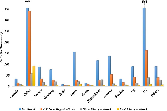
Quantitative scenario of worldwide electric vehicles and chargers.
Therefore, design of reliable and efficient power electronics converters for wireless chargers is the main concern of global technology providers. Soft-switching operation of high-frequency power converter can enhance the efficiency and energy transfer capability, with elimination of device switching losses and electromagnetic interference (EMI) as compared to hard switching operation.
According to Tesla [8], wireless power transfer is possible via radiative or nonradiative field depending upon their power transfer mechanism. In radiative power transfer, power can be transferred between two antennas over a larger distance. Due to omnidirectional behavior of these waves, the transferred power efficiency is very low. Non-radiative power is transferred between two or more electromagnetically coupled conductor loops as used in short and mid-range applications. However, this mechanism is also called near-field inductive power transfer (IPT) systems, where both the conductor loops are tuned at the same resonant frequency. Usually, a near-field IPT system is operated between the frequency range of 10 kHz (Tesla’s work [8]) to 200 MHz [9]. Power converter operation beyond 10 MHz frequency range will increase the initial cost and switching losses.
In the last two decades, several authors [10–20] have reported much WPT work to compensate effective impedance of circuit. After Tesla’s experiment, Schuder et al. [21] started experiments for biomedical applications at the University of Missouri-Columbia. In 2007, MIT scientist Soljacic and team developed a strong coupled magnetic resonance to light a 60 W bulb with 2 m air gap [22]. In 2010 first wireless power standard ‘Qi’ was proposed by the wireless power consortium, in which hundreds of companies working for low power mobile and laptop charging pads [23]. GFMTDI, Berlin developed a Bombardier PRIMOVE IPT charging lane of 200-kW [24]. Recently, the ChargePoint company announced the installation of 400 kW DC Xtreme fast chargers in light-duty vehicles, i.e. Tesla 3 and Porsche Mission E [25].
This paper is divided into two parts. In first part, a technical review of wireless power transfer system is presented, which covers the basic principle, classification of various WPT systems (Two coils, Four coils, and Domino resonators), analytical equations and results for the various position of field repeater. In second part, a compressive review of soft-switching realization techniques for WPT systems is presented. It covers the compensation techniques, steady-state analysis methods, human exposure and challenges to future technologies. In the series of existing inventions, various configuration and operating frequency possibilities of the WPT system with enhanced power transfer capability are classified in Section 2. Section 3 explains soft-switching realization methods and all reported research work on soft-switched WPT systems are discussed in Section 4. Human body exposure and applications are discussed in Sections 5 and 6. Further, conclusion and future scope of soft-switched WPT systems are discussed.
In near field WPT systems, inductive and capacitive coupling with high-frequency power electronic converters is used to transfer power from sending end to receiving end without any physical contact [26]. Classification of various types of the WPT system with frequency ranges is shown in Fig. 2. Capacitive coupling is generally used for low power applications [27]. Inductive power transfer topology can transfer power between moving or isolated objects even in adverse conditions like underwater and mining systems [28,29]. However, inductive coupling is capable of transferring power from a few milliwatts to hundreds of kilowatts [30,31]. It has a property to transfer power from low power range applications as biometric implant devices, artificial heart and monitoring sensors [15,32–36] to high power range applications like battery charging for an hybrid EVs, monorail [14,37–40].
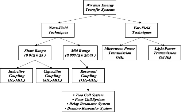
Classification of wireless energy transfer system.
IPT system has many unexplored potentials that may develop more reliable and efficient wireless power systems. IPT systems transfer power from the source end to load end over a large air gap between two magnetically coupled inductors. The large air gap causes higher leakage current which increases proximity losses in windings of coupled inductor [41]. Hence, higher circulating current decreases the efficiency of system for large air gaps as shown in Fig. 3.
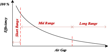
Efficiency of WPT systems with air gap variation.
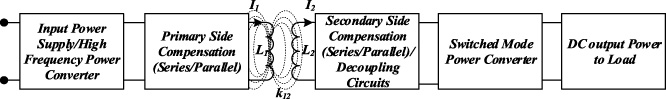
Conventional IPT system.
A conventional IPT system is represented in Fig. 4, where a compensation technique is used with inductor and capacitor to tune receiving and sending end circuitry at same resonance frequency. Resonant current flows through the tuned circuit and appears as a boosted voltage (In case of parallel tuning) or boosted current (in case of series tuning) across the load. Therefore, output power at receiving end as:
Output power S
U
is the product of open circuit voltage and short circuit current across the pickup system. The open-circuit voltage V
oc
and short-circuit current I
sc
as follows:
The equivalent circuit of IPT systems is same as the transformer working principle. Therefore, a mathematical model is explained using Kirchhoff’s law for N magnetically coupled coils shown in Fig. 5 [31].
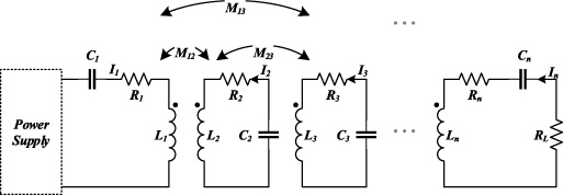
Equivalent circuit diagram of magnetically coupled multiple resonators.
Maximum power transfer depends on matching of source and load side impedance values, also known as impedance matching method. An equivalent circuit diagram of an AC power source and an equivalent load is shown in Fig. 6(a), where, R
S
+ jX
S
is the source impedance and R
L
+ jX
L
is the load impedance. Maximum power transfer from source to load side can be realized by matching impedance values as R
S
= R
L
and X
S
= −X
L
. Larger value of R
L
than R
S
decreases the output power but increases the efficiency of the overall system as shown in Fig. 6(b) [42]. It can be concluded that at ratio R
L
∕R
S
= 1, delivered output power to the load is maximum but at the same instant, energy efficiency of maximum power transfer is only 50% as expressed in Eq. (5) [31].
This concept is only applicable for low power applications up to several milliwatts mostly in radio-frequency applications. A four-coil system has low energy efficiency of only 15% even though maximum power transfer between source to load is 40% with the air gap of 2 meters [13]. These statistics show the limitation of impedance matching principle in mid or high-power applications.
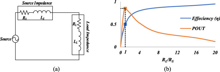
(a) Equivalent circuit of an AC power source and an equivalent load. (b) Variations of energy efficiency and output power as a ratio of R L and R S .
As discussed earlier, low source impedance selection in power converters increases energy efficiency in inductive power transfer [43,44]. Lower value of source resistance also reduces I
2 R
S
losses, which improves the energy efficiency capability. Use of air core resonator nullify the magnetic losses and reduces condition losses across coil resistance [31]. Generally, copper or litz wire wound resonator coils are used to reduce the winding losses under high-frequency operation [45]. Therefore, the overall energy efficiency of the system as shown in Fig. 5 is:
Maximum power transfer has limitations in mid and high range power application. Therefore, frequency splitting and frequency bifurcation phenomenon are used to maximize power transfer in mid-range power applications. When maximum power transfer is not extracted at resonant frequency within the over coupled region, the maximum power transfer of system operates at two splitting frequencies or more than two bifurcated zero phase angle (ZPA) frequencies [11,16,17,46]. Splitting frequencies are the two frequencies close to the resonant frequency, which provide maximum power transfer operation under the over coupled region. According to Huang [17], the reported resonant frequency is 10 MHz, but maximum power transfer occurs at two splitting frequencies viz 9.5 and 10.5 MHz, even though maximum efficiency occurs at normalizing resonant frequency. In frequency bifurcation, two or more bifurcated frequencies will exist except resonant frequency, for maximum power transfer operation of system [11]. Hence, maximum power transfer can be possible by using frequency splitting and bifurcation phenomenon even in a lower coupling coefficient case. A brief comparison of frequency bifurcation and splitting concept for two Coil series–series (S–S) resonant coupling IPT system is shown in Table 1.
Two Coil S–S resonant coupling WPT system frequency bifurcation and splitting concept
Two Coil S–S resonant coupling WPT system frequency bifurcation and splitting concept
The classification of two coil, four coil, relay and domino resonators are presented in Table 2. Figure 7 also explains the variation of the input impedance of circuit for two coil and four coil system for three different coupling regimes. First one is the over coupled regime, where external quality factor is less than internal quality factor. The second is critical coupled region, where external quality factor is equal to internal quality factor and last one is the under coupled regime, where external quality factor is greater than internal quality factor. The internal quality factor depends on the property of material and surface-roughness. Apart form this, external quality factor depends on the position, coupling of resonators and waveguides.
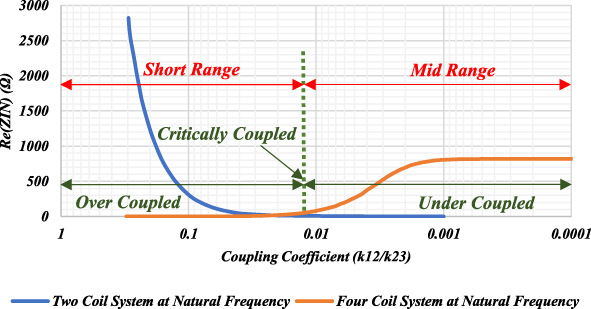
Input impedance variation for two coil and four coil system.
Various wireless power transfer systems
Wireless power transfer over large air gaps require compensating inductance, capacitance and superconductor devices to increase the coupling coefficient, which makes the system expensive and bulky. Such compensation techniques increase conduction losses in coils and loading on source/load resistances. Domino resonators are nonadjustable coils for multi-direction power flow, having slightly different frequency operation instead of resonant frequency [47]. The domino resonator thus is able to generate a uniform magnetic field using the parameters of winding. Covic et al. [37] proposed a multiple transmitter system to maximize receiving end power range, but the method is not applicable for coaxially connected coil system [48]. Lee et al. [49] presented an idea for the optimum power transfer with multiple intermediate repeater resonators and enhanced magnetic coupling, even at higher air gaps than coil’s diameter [50]. A three-dimensional thick spiral coil system is investigated to reduce skin and proximity effect by controlling winding resistance [12].
Systems with odd and even number of repeaters
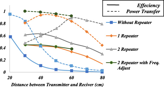
Maximum power transfer between over coupled resonators occur only at two split frequencies close to the resonant frequency. At the other hand, these frequencies decrease the transfer efficiency [16]. An analysis of power transfer between transmitter and receiver was done by Ahn et al. [54] by placing even and odd number field repeater as shown in Table 3.
Conceptual analysis of odd and even number field repeater
Conceptual analysis of odd and even number field repeater
By placing the repeaters at various positions, author concluded that odd repeater coils are beneficial for maximum power transfer at resonant frequency. One repeater coil case also provides ZPA operation of output load voltage and current. On the other hand, frequency of even number repeater is not responding to the resonant frequency of receiving end and sending end coils (ω = ω o ). Therefore, output power decreases gradually between receiving and sending end [47,53]. Maximum efficiency and power transfer capabilities for even and odd repeater system are plotted with distance variation in Fig. 8 [54].
Distribution of magnetic field is uniform in coaxially displaced resonators like straight-line system, but non-coaxially displaced resonators have different magnetic intensities at different points. A mathematical model was developed to understand the power flow in various non-coaxial domino resonators and investigated the vector diagrams for various loading conditions [47]. The author concluded that loading on odd number resonator would perform better as compared to loading on even number resonator. Counteraction of current vector in even numbered resonators decreases the efficiency distribution. Maximum power flow and higher efficiency in even numbered resonators is only possible at the resonant frequency operation (ω o ), but odd numbered resonators have optimized operating frequencies close to resonant frequency. The power delivery and efficiency response towards load is also better in odd-numbered resonators. In even resonator case, if loading is done on odd number resonator, it gives higher efficiency. For example, in case of 4 and 8 numbers of resonator system, higher efficiencies were achieved when loading was applied on 3rd, 5th and 7th number resonator and near zero efficiencies reported on 2nd, 4th, 6th, and 8th number resonator as shown in Fig. 9.
Efficiency and power transfer capabilities against air gap variation.
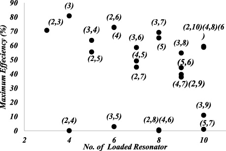
Maximum efficiency distribution to the sequence number of loaded resonator.
To overcome the above-mentioned problems, much research has been reported [55–58] to utilize stored energy across leakage inductance using various converter topologies like flyback, resonant, quasi-resonant and self-resonant converters. Coupling coefficient can be improved by using series and parallel resonant circuit topologies. In conventional IPT systems, primary of the loosely coupled transformer is supplied by the PWM controlled half/full bridge inverter circuitry. These compensation techniques have four basic primary to secondary circuit configurations, i.e., series–series (SS), series–parallel (SP), parallel–series (PS), and parallel–parallel (PP) as shown in Fig. 10.
Series–series configuration needs a series resonant capacitance to improve the coupling coefficient at high air gaps, which increases the conduction losses. In series–parallel compensation, the primary requires a large and costly series inductor to regulate resonant current. Load side capacitance value also depends on the coupling coefficient and a quality factor, which increases losses. Characteristics of series–series and series–parallel compensated systems were discussed by Zhang et al. to understand the above-mentioned problems [59,60]. A detailed description of SS and SP topologies are categorized in Table 4.

Various series and parallel resonant circuit topologies: Series–Series, Series–Parallel, and Parallel–Parallel.
In the existing literature, much work has been reported to improve secondary pickup controller efficiency and voltage regulation. A pickup circuit simplify the analysis, but reduces efficiency by 4% (at rated power level) to 8% (at light load power level) [61,62] of IPT systems. A hard-switching decoupled controller is used for high power application [63]. The main disadvantage of hard switching control is the high inrush power demand at pickup under normal power regulation, which reduces the track current and interrupts power flow in multiple pickups system [64]. A parallel tuned pickup will act as a constant current source and series tuned pickup will act as a constant voltage source [46]. Series controller operation is beneficial under high-frequency-high-current (HFHC) application like incandescent lights. It not only reduces the additional component like bulky inductor of buck converter but also limits the EMI, inrush current and harmonics [61]. Multiple series pickup systems were analyzed by Boys et al. [48] for HFHC application with quality factor variation from 0.01 to 0.1. A secondary side series compensation improves efficiency up to 10%–20% more than parallel system through large air gaps [65]. In case of low power demand, a cascaded buck converter with the series tuned circuit can be used for decoupling of power flow. It also has some drawbacks, i.e., increased losses due to two stages conversion (AC–DC & DC–DC), additional DC inductor increases cost and requires extra DC capacitor to reduce ripple in DC output voltage. Which increases high inrush current [up to 200%] in resonant components and stress across the active switches of converter [66]. In parallel tuning circuit, switches control the boost level of voltage and also eliminates real and reactive power loading on the input source. It requires a high-value capacitor instead of inductor.
Parameter description of SS and SP compensation topologies
In case of high output power, parallel pickup controller circuit is generally used for decoupling application [37]. It also has some disadvantages like, reflecting real and reactive power to source, requires a large inductance value to ensure CCM operation and availability of low output voltage [67]. Current-fed parallel–parallel tuned resonant converter can generate high resonant load current even in low input source current. This topology improves efficiency, output voltage regulation with minimum error and provides better control under sudden load change. A series/parallel compensation is also be possible by adding an additional variable capacitor with coils for tuning of resonant converter [62,68,69]. A fast-pickup controller is required to limit the change in inductor current (di∕dt) during the soft-switching transition of active switches. Regulation of inductor current improves inrush current and EMI but also needs extra filtering circuit for harmonic elimination [61]. System output contains high order ripples due to parameter variation, which can be controlled if the chosen frequency sample is faster than parameter variation. Effect of additional filter inductor (L f ) is also not inevitable although it does not disturb the resonant frequency. Hence, the selection of L f should be made accordingly with aim of less voltage stress (5% of source voltage) and less peak current through converter’s legs (less than MOSFET rated current) [40]. By placing a high inductor value at the output side, the same converter can operate as a current source or voltage source converter [70]. Therefore, the sampling frequency is controlled by the time constant (L DC ∕R DC ) using a DC filter in pickup circuitry [71].
High-frequency operation of power electronic converters having condition losses due to skin and proximity effect of AC winding resistance and switching losses at the time of switching transition [72]. However, use of appropriate resonant coil design and soft-switched converter can overcome such problems to make IPT system more efficient and can transfer maximum energy. An inherent frequency range is required to achieve soft-switching opeartion of converter. Operation of converter below resonance/above resonance provides benefits of zero crossing of current (ZCS)/Zero voltage switching (ZVS) at turn off/turn on transition. High-frequency resonant converters have many limitations like increased voltage stress on switches; high current level; energy loss across parasitic elements and wide frequency range with specific load requirement. ZVS mitigates the MOSFET switching losses and provides efficienct operation. ZCS eliminates turn off power losses in IGBTs, but significant switching losses are retained like turn on switching losses, diode reverses recovery losses and leakage of charge stored in parasitic capacitor at high voltage. IGBTs have some disadvantages viz. high voltage drop causes higher conduction losses; restricted frequency range below 20 kHz for high power application. Consequently, high-power-high-frequency operation of converter is possible by using ZVS [73,74].
Steady state analysis of soft-switched inductive power transfer systems
For steady-state analysis, input source should be assumed as a DC source. Steady-State analysis of the sinusoidal inductive power transfer system is done by using the AC impedance method, but it is not appropriate for non-sinusoidal systems [75,76]. In resonant converter, a tank circuit connected to switch network, which contains high order harmonics. In that case, steady-state ac analysis can be done by obtaining ZPA frequency of tank circuit, which is different from the original resonant frequency [77].
An IPT system can operate at multiple zero crossings of voltage and current values. To analyze the steady state and dynamic behavior of those points, generalized average steady-state analysis (GASSA) method is used. The main drawback of this approach is the requirement of prior information of resonant frequency to decrease coefficient variable counts. GASSA method is a periodic time function of PWM pulses, which computes the Fourier coefficient to calculate the derivative frequency of the system. Value of Fourier coefficient retained one or negative one for sinusoidal behavior and zero for slow changing predominantly DC behavior [78,79]. In practical applications, modeling and calculations become more complex. Among various discrete time modeling methods [80,81], the stroboscopic mapping method is used for steady-state analysis of multiple zero crossing voltage/current points and nonlinearities in converter at the unspecified resonant frequency [82].
High frequency (MHz) operation of soft-switched power converter
Half-bridge and full bridge converters are generally used for WPT applications, but it has the limitation of operating frequency up to several of kHz. For higher frequency operation (MHz), power amplifier topologies can be used. A comparative analysis was done by Huang et al. [11] shown in Table 5 for various power amplifiers. Class A, B, AB and C are the linear and less efficient amplifiers, which are not suitable for resonant coupling. Moreover, switched mode power amplifiers like class D, E, DE and F have their respective merits and demerits [83]. A Class-D power converter is used by Galbraith and Joung et al. [32,36] to overcome the large leakage inductance problem due to transcutaneous gap and alignment. In case of the low magnetic coupling, a parallel-resonant class D oscillator was used to achieve high efficiency using splitting frequency tracking scheme and maintain the output voltage constant even in load variation [60]. Among all switched mode power amplifiers class E is suitable for soft-switching realization for high-frequency operation (>3 MHz) [84].
Classification of various power amplifiers for the realization of soft-switching [11]
Classification of various power amplifiers for the realization of soft-switching [11]
Resonant tank circuit smooth the oscillation in sinusoidal output and make system reactive, but load variation and low magnetic coupling disturb the tuning of tank circuitry. This disturbance changes primary and secondary side impedances dynamically which causes frequency drifting. This makes secondary side operation unstable and limits the required output power. Design of efficient controller to overcome such problems and meet load power demand are the interest area of investigation [37,46]. Various control strategies have been implemented to control secondary pickup power flow control, such as the addition of a passive element in series and parallel, shorting control, dynamic tuning/detuning and directional tuning [51,85,86]. Hussmann et al. [87] proposed the shorting control method in PWM/Hysteresis controlled buck converter to regulate the load current. Main disadvantage of this method is the flow of shorting current through the switch during the shorting period, which causes higher condition losses in system. Mostly IPT systems face such serious problems under no or light load condition. In dynamic PI tuning/detuning control, a linear/switched mode inductor/capacitor is used to compensate such flaws but the use of conventional PI controller only possible at one side of system between two nearest optimized points. Valtchev et al. [63] discussed the dynamic behavior and magnetic modeling of primary and secondary coils by using the Finite Element Method Magnetics and Mag-Net software platforms. A fast and responsive controller is required to eliminate power losses and force system to operate near the soft-switch operation point [51]. Therefore, prior information of optimized regime is required to avoid wrong direction tracking [88]. In directional tuning control method, sense of current and previous control input is required to track direction accuracy [86]. Therefore, circuit retunes itself by using the algorithm for optimized power over full bell-shaped curve. Larger changes in tuning circuitry gives better and fast results with unwanted dynamics in system. Smaller steps make system too slow and takes more time to track proper direction.
Phase angle lock control
If various resonant variables are defined, frequency modulation will be different for each loop as well each period. If efficiency is not the prime concern, pulse width modulation is preferred for low output power demand, but in high power applications, frequency modulation is preferred for better efficiency [63]. Control on higher frequency range is required in the frequency modulation method, which deviates the effective load frequency. Tight tuning regulation at different loading condition requires a phase angle control to prevent reactive loading at the primary side and makes unity power factor operation of the system [89]. To overcome these issues, a phase lock loop-based frequency modulation method was proposed to lock switching frequency at a certain value slightly above/below than load effective frequency and a coupling insensitive gain control was achieved for a given frequency range [33].
Detuning/shorting current control of resonant tank circuit
A resonant converter with multiple pickup controller requires a large number of bulky components and these cascaded systems have high losses in each stage. In these types of the converter, output voltage regulation is achieved by primary current control and optimum frequency control techniques [36]. Primary side control method is applicable only where a single secondary pickup system is used. For multiple pickups, secondary side reactive compensation is done by adding a series capacitor or inductor with tank circuitry. Soft-switching of the converter was implemented by using an additional series capacitor to reduce the effective impedance, magnetizing current and ohmic losses [90]. A variable inductor is used to detune resonant circuit (Shorting control method) through two switches, which resonate with a parallel capacitor and bound system operation soft-switching with good power regulation. Shorting control method is easy in operation but has higher power losses at shorting switches. Shorting switches are operating almost all the time to maintain output capacitor voltage. However, the continuous flow of short-circuit current in the pickup controller increases conduction losses in the system. Addition of series capacitance can compensate system reactance for the soft-switching operation of a single pickup load power regulator. But this system is not applicable to supply multiple loads or sensors at the same time [85]. A series LCL pickup system was experimented to eliminate the real and reactive power loading on the power supply [91]. Addition of a series capacitor with pickup inductor allow the short circuit current to exceed maximum load current. A series–parallel LCL controller topology was used with the soft-switching transition of switches, which provides unity power factor at the pickup, and continuous conduction of rectifier at resistive load [92]. A linear approximation was made to balance real and reactive loading by adding an external reactive component and made LCL tuned controller operation at unity power factor [69]. By adding a series capacitor, circuit leakage inductance can be increased, but it causes higher voltage and current stress on resonant circuit elements [68]. The need of an extra bulky inductor is the main limitation of LCL tuned system. To enhance the energy boost at variable secondary side, a switched capacitor controlled LCC parallel resonant circuitry was used with primary side of system [34]. Switched capacitor reduces AC ripple content at load side and operates system efficiently. By increasing the primary inductance in LCC tuned system, the ZVS operation of switches (leads the primary voltage over equivalent inductor current by the angle of −90° to −180°) and reactive power compensation can be achieved [18].
Frequency tuning algorithms
Various methods are reported to realize the soft-switching operation of using frequency tracking methods. A passive frequency tracking method (commercial range of 110–205 kHz) was used to detect the zero crossing of current in resonant circuits [34]. An initial control is required to generate oscillations for this method. Detection of an accurate zero crossing is also not possible due to the delay and disturbance in gate driver and feedback control circuit. Increasing operating frequency makes the system more complex and drops system performance drastically. Therefore, an active tracking method was realized on sets of high order differential equations [78]. Mismatching between the driving frequency and soft-switching frequency was occurred due to the short current in switching network and resonant tank network. The increased mismatch produces an excess flow of short current that can harm switching devices. Therefore, a fast frequency tracking method is required to overcome such problems. A short current active frequency control was reported the drifting of switching frequency from the inherent frequency [93]. In case of higher switching frequency than the inherent operating frequency shifts switching transitions before zero voltage switching points. Due to this mismatch, short current will produce and shift the resonant voltage below/above zero crossing. Shorting paths flow heavy short current and demand sharp peaks from input current. In case of lower switching frequency than the inherent frequency shifts switching instants after zero voltage switching points. Due to this mismatch, produced short current value will be a constant inductor current and much lower as compared to the higher case. A fuzzy-based primary current regulation was proposed, in which change in signals was used to update operating frequency and generate gate pulse for guaranteed soft-switching operation even in load variation [65]. Another fuzzy controlled parallel bi-directional tuned pickup was proposed to track direction using larger step size method by variable capacitance value [94].
Synchronous clamped control
Power sharing in the IPT systems causes disturbances in phase angle and conduction angle, which affects the performance of converters. To implement soft-switching operation and maximum power transfer of system, VA loading and phase angle between the input voltage and current should be zero or greater [60]. Therefore, such disturbances can be utilized in synchronous clamp mode method to control phase and conduction angle simultaneously, which is updating the output voltage information twice in a resonant cycle [68]. Tuning frequency value maximizes the corresponding quality factor. A phase angle control method was proposed, where circuit reactance was investigated to make converter operation soft-switched between specific frequency range [59]. Calculated phase angle expressed as:
As discussed in Section 2.1.3, in case of light load and loose magnetic coupling, frequency bifurcation phenomenon may increase the soft-switching operation points in the system. Frequency bifurcation not only shifts the system operation towards one stable soft-switching frequency point but also realizes maximum power transfer near middle soft-switched operation point. A frequency bifurcation phenomenon based ZVS follower algorithm was proposed in a current-fed push-pull (CFPP) parallel–parallel tuned system [82]. The algorithm can sense the capacitor/resonant tank shorting current and regulate the switching frequency to realize ZVS before/after frequency bifurcation. Another stroboscopic mapping method based ZVS bifurcation system illustrates three possible ZVS operating points, where AC impedance matching ensures system operation towards middle ZVS point and enhances end to end system efficiency [10].
The current status and reported work till date in soft-switched wireless power transfer system are shown in Fig. 11(a)–(c). It can be concluded from Fig. 11(a) that 87% of total work is performed in the last decade for SSWPT systems. Therefore, the trend of research is getting popular day by day, and vast possibilities are in the direction to be determined. Figure 11(b) illustrates the systems operating frequency variation from kHz to MHz regime. More than 90% of work is performed between the range of 10–500 kHz. Figure 11(c) shows the capacity wise trend of the reported work. In which 25% of the work performed is below or up to the level of 10 W, mostly investigated for biomedical implants and artificial heart devices. Approximately 60% of work is performed between the range of 10 W to 1 kW, and only 17% is reported above 1 kW range. Feasibilities and findings of various reported experiments and analytical studies by researchers are reviewed for soft-switched wireless power transfer systems in Table 6.

Miscellaneous Trends (a). Year wise reported work; (b). Experimented operating frequency variation; (c). Experimental power capacity range.
Experimental study for the soft-switching wireless power transfer system
Patents related to soft-switching topologies in WPT
Most of the companies are working on soft-switched resonant inductive coupling system to eliminate switching losses as well as higher efficiency in modern converters. In recent work, western countries like the USA, China, and Taiwan have extensively investigated soft-switching topologies to enhance efficiency. The focus of the research is to analyze the power regulation, reactive stress reduction, and ZPA operation using soft-switching topology in WPT systems. Many patents exist in the area of SSWPT topologies. Table 7 illustrates the brief review of the soft-switched wireless power transfer system.
Human exposure
Low-frequency power transfer EMI effects can be mitigated using EM shields, whereas in high frequency; high power transfer has adverse effects on human bodies. For safe power operation directing guidelines were provided by ICNIRP and IEEE as shown in Fig. 12. ICNIRP guidelines describe general public and occupational operation limits of exposure for time-varying electric and magnetic fields from 1 Hz to 300 GHz frequency range [109]. IEEE standard safety guidelines describe one set of operational limits for human exposure over the frequency range of 3 kHz to 300 GHz [110]. Christ et al. [111] examined the normalized specific absorption rate (SAR value) on the structural model of an adult or child human body for mid-range four coil systems. Modeled structure backs were placed 10 mm away from a resonator test loop in axial, coronal and sagittal planes. From both the safety guidelines, it should be noted that high-frequency-high-power operation (up to 10 MHz) makes electric and magnetic fields level more dangerous for human body.
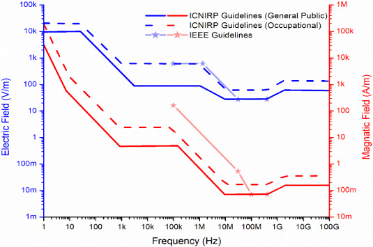
ICNIRP and IEEE standard safety guidelines for exposure to time-varying electric and magnetic fields.
SSWPT systems are unaffected in dirt, ice, moisture, and other environmental conditions. It eliminates the carbon residue through frictional contact between carbon brushes and metallic platform [112]. Figure 13 shows the application-wise reported work in this field.
In biomedical application, implant devices require 15–35 W power from rest to heavy running condition and used to exchange data from the outer world [113]. Monitoring and controlling of required voltage make device operation safe and reliable [36]. Chen et al. [33] experimented two air core windings to overcome core losses, heating of tissues with reduced weight for an implantable device. Covic et al. [35] reported a diode clamp based soft-switched CMOS implant neural prosthesis with bi-directional information data flow in power transmission. The author concluded very less heat dissipation at transmitting and receiving side circuitry (0.1 mW T x and 3.5 mW R x ). Budgett et al. [95] experimented a soft-switched high-frequency IPT system to power an implanted pickup unit and recorded accurate ECG data of moving object away from the transmitter side up to 5 meters.

Application wise reported work.
In industrial applications, wireless power and information transfer has three major problems in essential coupling: (1) The capability of efficient power and communication signal transfer; (2) noisy EMI signals and (3) ecological inconsistency. Electric drives are required for robot arm movement, but elimination of loose cables is necessary for optimum operation. Multiple sensors with random turn on/off without any physical contact are used to supply moving object case [30]. In the automation system, inductive or capacitive sensors are used often, to measure electrical and magnetic conductivity, and photo electronics and ultrasonic sensors are used to sense distance and dimensions of the system [114]. According to Lin et al. [115], electrification of 1% roadways with dynamic chargers can increase the market share of plug-in EV by 65%. If charging stations of 3.3 kWh/minute are mounted on each scheduled stop of the bus lane, then average 5-minute wait can maintain the 76% SoC [25].
This paper presents a critical review of SSWPT systems. Literature review categorized the available facts, recent trends and barriers of SSWPT systems. Presented work gives the evidence that renewable energy based SSWPT system can be used as an emerging technology for the commercial and industrial application. Especially, the automobile sector needs a technological advancement to reduce carbon dioxide levels in the atmosphere quickly. Basic principle and classification of WPT techniques along with soft-switching realization methods, and their human exposure and safety field guidelines are discussed in detail. There are many aspects of SSWPT technology that still need to be investigated, and it would be able to provide immeasurable possibilities in emerging power electronics technologies.
Nomenclature
Wireless power transfer
Soft-switched wireless power transfer
Japan aerospace exploration agency
Electric vehicles
Electromagnetic interference
Transcutaneous energy transmission
Inductive power transfer
Continuous conduction mode
Source resistance
Load resistance
Source Inductance
Load Inductance
Output Power
Current in the ith coil
Coil winding resistance in the ith coil
Coil winding inductance in the ith coil
Coil winding capacitance in ith coil
Mutual Inductance between coil i − j
Coupling coefficient between the i − j coil
Apparent power
Duty cycle
Quality factor
Open-circuit voltage
Short-circuit current
Angular frequency of the ith coil
Resonant frequency
Effective capacitance
Short Current Detection time
Generalized average steady-state analysis
Specific absorption rate
High-frequency high current
State of charge
Zero phase angle
Input Impedance
Impedance of ith coil
Scattering parameters between coils
Magneto-inductive
Distance between coils
Radius of the ith coil
Printed circuit board
Transmitter coil
Receiver coil
Repeater coil
Zero voltage switching
Zero current switching
Nominal frequency
Series–series
series–parallel
Parallel-series
Parallel–parallel
Filter inductor
Voltage transfer function
Current transfer function
Field-programmable gate array
Pulse width modulation
Series load series resonant
Voltage source controlled
Current source controlled
Phase difference angle
Frequency mismatch time
Electromagnetic field
Electrocardiogram
Current fed push-pull