
Abstract
Metallic sleeves are widely used to ensure the mechanical integrity of rotors in high-speed permanent magnet (PM) synchronous machines (HSPMSM). However, in traditional high-speed rotors, the PMs which are very weak in tensile stress cannot be well protected by sleeves. Furthermore, the material properties of both the sleeves and PMs cannot be fully used. As a result, the high-speed running range of the machines are limited by the mechanical strength for a given rotor size. In this paper, taking a 230-kW 35-kr/min prototype as an example, the mechanical strength issues of the rotor are investigated by analytical method and finite element analysis (FEA). In order to overcome the unbalanced protective effect of the sleeve and make fully use of the materials, an optimal sleeve, as well as an improved rotor structure, is presented. The comparison results show that the optimized sleeve has well balanced protective effect to the PM as well as good utilization of materials, with a resultant increase in maximum speed of nearly 40% with respect to the prototype.
Introduction
High-speed machines are gaining prominence and are increasingly employed in applications such as micro-gas turbines, turbo-compressor, vacuum pumps, flywheel energy storage system, high-speed motorized spindles and aircraft electrical power systems due to many merits [1–6]. A commonly perceived advantage of high-speed electrical machines is the reduction of system weight and volume for a given magnitude of power conversion [5,6]. Moreover, incorporating a high-speed electrical machine into a traditional multi-stage transmission system, such design eliminates the need for complicated link mechanism and offers higher mechanical driving efficiency and reliability [7,8]. Permanent magnet (PM) synchronous machines (PMSM) are well-suited for high-speed applications due to their high efficiency, high power density, and high power factor [7,9]. Therefore, the drive toward research and development in HSPMSM has shown rapid growth in both industry and academia.
In HSPMSM, the mechanical strength issues of the rotor, especially of the PM, should be well handled. PM materials are very weak in tension, although they are able to withstand large compressive stress. To ensure the mechanical integrity of high-speed rotor assembly, PMs are often protected via sleeves [4,5]. Then the common used rotor topologies in HSPMSM are the surface-mounted PM rotor [10,11] and the solid-PM rotor [12,13]. Compared with the surface-mounted PM rotor, a solid PM is utilized in the solid-PM rotor and the shaft is eliminated.
The use of a retaining sleeve provides some significant properties from not only mechanical strength but also thermal points [14]. Above all, the sleeve material must have high yield stress but low density in order to have a good protective effect to PMs. From the thermal point of view, the loss density of rotor in a HSPMSM is much higher than that in a conventional machine. The rotor cooling is more difficult since all the heat is dissipated through the air. Then the material of sleeve should have: (1) the lower electrical conductivity to reduce the eddy current loss caused by high-frequency harmonics; and (2) the higher thermal conductivity to improve the cooling condition. Carbon fiber is often used to protect the rotor due to its superior mechanical properties [15,16]. However, its thermal conductivity is much smaller than that of metallic materials [14]. The most widely used metallic materials for sleeves are nickel-chromium-based alloy Inconel [17,18] and titanium [19,20]. Some research works about the mechanical strength of rotor with metallic sleeves have been reported in previous literatures.
In Refs. [1,4,8,20,21], the issue of mechanical stresses in rotor is highlighted as an important consideration. Refs [8] and [21] gave the analytical models to calculate the mechanical stress for the surface-mount PM rotor and the solid-PM rotor, respectively. It is clear that the interference fit, the rotating speed, and the temperature have a great influence on the mechanical properties of the rotor. Reference [18] studied the influence of three different sleeve metallic materials (Titanium, Sus304 and Inconel 718) with two different PM materials (N43SH and Sm2Co17) on the mechanical stress of a HSPMSM. The relationship between sleeve thickness and interference fit is also examined. Reference [22] described an observed shear stress concentration caused by the Poisson effect which can lead to magnet cracking and rotor failure. It is also reported that the use of lubricants to reduce the friction between the PMs and sleeve is beneficial to avoid the cracking at PMs axial ends.
In this paper, the unbalanced protective effect of sleeve and the underutilization of materials of sleeve and PM in traditional HSPMSM are analysed by analytical method and FEA. With the results of analysing the mechanical strength, an optimal high-speed rotor structure which has well balanced protective effect to the PM is proposed.
Description of prototype
The HSPMSM studied in this paper is used as a direct-drive turbo blower applied in the wastewater treatment facilities. The studies in the literatures have shown that energy savings in excess of 35% can easily be achieved by replacing traditional blowers [23]. Moreover, the turbo blowers driven by high-speed machines have higher reliability and durability, while with lower noise [1]. The required specifications of the HSPMSM to be designed are listed in Table 1. Air bearings which use ambient air as the working fluid and require no external pressurization are employed in the machine. They operate contract-freely and with no abrasion [24]. The only friction results from airflow in the air-gap. Due to the characteristics of high power density and poor heat dissipation, the air cooling is utilized in the prototype.
Required specifications of HSPMSM
Required specifications of HSPMSM
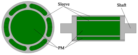
Figure 1 shows the cross section of simplified geometry of the HSPMSM. The rotor is composed of the cylindrical PM, the sleeve, and the shaft. The shaft is divided into two parts which are inserted into the sleeve from the two sides respectively with interference fit. Detailed parameters of the prototype and the related material properties are listed in Table 2 and Table 3, respectively. Based on the design proposal one prototype was manufactured as shown in Fig. 2. The electromagnetic and the mechanical characteristics as well as the operational stability of the prototype were verified by experiment.
Main parameters of prototype
Properties of the materials for sleeve and PM
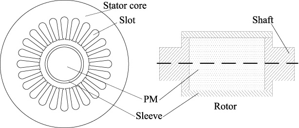
Cross section of simplified geometry of HSPMSM.

Prototype HSPMSM. (a) Motor. (b) Stator. (c) Rotor.
The stresses on PM and sleeve can be divided into two kinds, namely the static stress and the dynamic stress. The static stress is caused by the static interference fit after assembling while the dynamic stress appears when the rotor is rotating. Because of the static interference fit size is known, the static stress can be calculated easily based on the theory of the thick-wall cylinder [16]. The dynamic interference fit size is affected by the expansion due to the centrifugal forces and the rising temperature. The dynamic stress can be calculated by considering the temperature and the rotor speed at the same time.
After assembling, the static interference fit size δ
s
can be expressed as
The dynamic interference fit size will be changed by the expansion due to the centrifugal forces and the rising temperature when the machine is working. u
eiω and u
mω are the displacements of the sleeve inner surface and the PM outer surface, respectively, in the radial direction due to the centrifugal forces.
The displacement of the sleeve inner surface u
eiT
and the PM outer surface u
mT
can be calculated by considering the rising temperature via
The dynamic interference fit size δ can be calculated by considering the centrifugal forces and the rising temperature via
The static pressure P
s
between the sleeve and PM and the dynamic pressure P by considering the centrifugal forces and the rising temperature, can be expressed as
Since the PM is a solid cylinder, the radial and the tangential components (σ
rms
and σθms
) of the static stresses have the same value, which equal to the static pressure, that can be expressed as
For the static state, the radial and the tangential stresses (σ
res
and σθes
) of the sleeve can be expressed as
For the dynamic state, the radial and the tangential components (σ
rm
and σθm
) can be expressed as [8]
From the mechanical stresses analysis of the rotor in Section 3, it is clear that the mechanical stress on both the sleeve and PM is heavily reliant on the interference fit size, the rotor’s rotating speed, and the working temperature of the rotor. Then it can be inferred that the stresses, or the protective effect of the sleeve will be changed with the change of working states, temperature distribution on rotor.
Working states of machine
In order to investigate the protective effect of the sleeve in different working states, four cases are studied: (1) the static state, (2) high speed and low temperature, at 35000 r/min and 20 °C, (3) low speed and high temperature, at 10000 r/min and 220 °C, and (4) high speed and high temperature, at 44000 r/min considering 10% over-speed and 220 °C. In order to simplify the contrastive analysis for different materials, the safety factor (F
s
) employed, and it can be expressed as
Figure 3 shows the result of F s in different cases. In Case 1, the static interference fit size equals to the design value 0.14 mm with no impact of centrifugal forces and thermal expansion. F s of the sleeve is low due to the large static interference fit size, but it is not the lowest one. The sleeve has the lowest value of F s in Case 2, in which the speed and temperature of the rotor are 35000 r/min and 20 °C, respectively. In Case 2, the interference fit is changed from 0.14 mm to 0.12 mm due to the centrifugal force. The compressive stress between the sleeve and the PM is reduced. However, the sleeve endures much higher centrifugal stress. As a result, the sleeve in Case 2 has the lowest value of F s . It reveals that the sleeve will endure a higher stress if the startup process is very quick. The values of F s for the sleeve and PM are both high in Case 3. It means that there is no risk during the process of deceleration. In Case 4, the PM is at the highest risk of cracking when the machine is working at the high temperature and the high rotating speed conditions, though the sleeve has a higher value of F s .
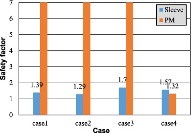
Safety factors in different cases (case 1: 0 r/min and 20 °C; case 2: 35000 r/min and 20 °C; case 3: 10000 r/min and 220 °C; case 4: 44000 r/min and 220 °C).
Overall, there are large gaps of F s between the sleeve and PM. Besides, the F s of PM is low while the sleeve has a higher value of F s . This is considered as one of the unbalance protective effect of sleeve.
HSPMSM has a higher power density but smaller volumes of the stator and rotor. This means that the loss density in a HSPMSM will be much higher than that in a conventional machine. Due to high rotating speed, the high frequency flux will induce larger eddy current losses in the rotor. Additionally, the friction losses and the gas-flow losses can account for a large proportion of the total loss [9]. HSPMSM mainly cooled by the air-gap flow, and all the losses in the rotor are dissipated by convection. Therefore, the rotor of HSPMSM has a higher loss density and a harsh cooling condition. The prototype employs the forced air cooling method as shown in Fig. 4. A cooling impeller is designed at the right side of the shaft. The cooling air is forced into the machine through the inlets, flowing through the air gap in the axial direction and then emitted through the outlet.
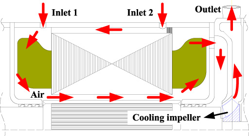
Cooling scheme of the prototype.
The temperature tests are carried and the results are listed in Table 4. It can been seen that the winding temperature at the inlet air side (left side) is higher than that at the outlet air side (right side) due to the cooling air path. Based on the actual cooling conditions as shown in Table 4, the temperature distribution of the motor is simulated by thermal equivalent network method and the results are also listed in Table 4. As can be seen from the comparison in Table 4, there are some differences between the calculation and test results, but the variation tendency between the two sides in the axial direction is in good agreement. There exists a large temperature difference between the two sides of the rotor. Detailed temperature distribution can be seen in Fig. 5.
Comparison of temperature results
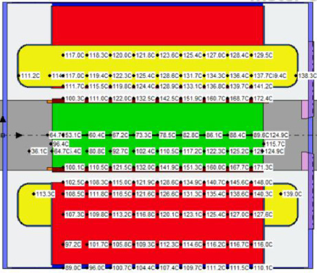
Temperature distribution of nodes at steady state.
The temperature of the cooling air in the axial direction gradually becomes higher, which will affect the heat dissipation of the rotor. Besides, the rotating rotor accelerates the cooling air to a tangential movement, leading to the flow path of the cooling air gradually becomes longer [21]. Then the temperature on the rotor side near the cooling impeller is higher than that on the other side.
Assuming the rotor has the same temperature distribution when its speed is 44000 r/min. The mechanical stresses of the rotor considering the temperature distribution in the axial direction are calculated by FEA, the results are shown in Fig. 6. The stress of the sleeve is an axis of change as well as F S of the PM due to the non-homogeneous temperature distribution along the axial direction. On the lower temperature side, the sleeve has the higher stress value which meets the requirement of mechanical strength, and the PM has a higher value of F S . On the other side, the PM is at the highest risk of cracking although the sleeve has a lower value of stress. The protective effect of the sleeve is different on both sides. This is considered as the second one of the unbalance protective effect of sleeve.
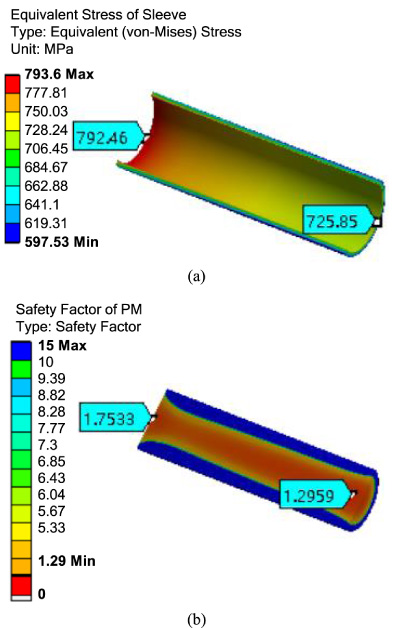
Von-Mises stress and F S distribution by FEA (44000 r/min). (a) Sleeve. (b) PM.
The mechanical strength of high-speed rotors with metallic sleeves is discussed considering three combinations of sleeve and PM materials in this section. The combinations of materials are listed in Table 5. The mechanical properties of the rotor based on different combinations of materials are investigated.
Combinations of materials
Combinations of materials
Figure 7(a) shows F s curves of sleeve in design #1 and #3 with different static interference fit sizes at the static state. For given dimensions of the rotor, at static state, the Ti6Al4V sleeve has higher F s with the same static interference fit size due to its lower Young’s modulus.
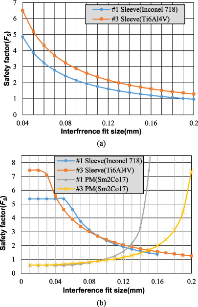
Variation of safety factor VS interference fit size. (a) Static state. (b) Dynamic state.
According to Eqs (7) and (8), if the static interference fit size δ is large, the pressure P and P s have a good value to guarantee the safety of the PM. The large δ ensures that the PM has a high compressive pre-stress to avoid cracking at working state. But δ should not be set too large, otherwise the sleeve may endure a high stress at the dynamic state or need a very high heating temperature during its assembling process.
Figure 7(b) shows the variation of F s considering the combined effect of thermal and centrifugal stresses under the dynamic state at 40000 r/min and 220 °C. As can be seen, the F s of PM will be increased as the increment of the static interference fit size. Meanwhile, the F s of sleeve is reduced gradually. The Ti6Al4V sleeve has higher F s no matter working at the static or dynamic states, whereas its PM sustains lower F s at high temperature and high speed.
In order to ensure the integrity of the rotor, F
s
should be set greater than the empirical value 1.37 for both sleeve and PM. From Fig. 7(b), the proper static interference fit sizes are 0.14 mm in design #1 and 0.16 mm in design #3, respectively. Then care must be taken to the required heating temperature for the two sleeves during the assembly process. The required heating temperature t
1 can be expressed as
Different PM materials are selected in design #1 and #2 as shown in Table 5. The maximum working temperature of Sm2Co17 and NNF38EH shown in Table 3 are 350 °C and 220 °C, respectively. The machine of design #1 has a higher possible working temperature without the risk of an irreversible demagnetization. The drawback of Sm2Co17 is the lower tensile yield stress, which may lead to the rotor not being able to operate at a high temperature.
Figure 8 shows the variation of sleeve Von-Mises stress and the PM F s versus the temperature of the rotor. The speed is set at 44000 r/min considering 10% over-speed. As can be seen, F s of Sm2Co17 in design #1 will be decreased as the rise of the temperature. Sm2Co17 may be destroyed when the working temperature is higher than 220 °C due to its low F S , although its maximum working temperature is 350 °C. Relatively, since the tensile yield stress of NF38EH is twice as Sm2Co17, the PM in design #2 has a higher F s when the working temperature is below 220 °C. Furthermore, the thermal expansion coefficient of NNF38EH is regarded as zero, the dynamic interference fit in design #2 is changed more than that in design #1. As a result, the sleeve in design #2 has significantly lower stress. However, the material NNF38EH has a lower maximum working temperature, which is not suitable for utilizing in HSPMSM.
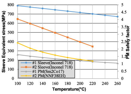
Variation of the sleeve Von-Mises stress and the PM safety factor with temperature.
As a whole, the properties of the general materials of sleeve and PM used in the traditional high-speed rotors cannot be fully used.
The unbalanced protective effect of the sleeve and the underutilization of the materials in HSPMSM have been discussed in the Section 4 and Section 5, respectively. It can be concluded that the interference fit between sleeve and PM will be greatly changed due to thermal expansion and centrifugal force, this is the root cause of the problems mentioned above. It is the natural flaw of the traditional high-speed structure. In order to overcome the drawbacks and improve the mechanical strength, optimal high-speed rotor structures should be adopted in HSPMSM. With comprehensive consideration of the critical influence factors as well as the assembly of the metallic sleeve, requirements for the optimal structures are summarized as follows: (1) the needed static interference fit size is smaller; and (2) the variation of the interference fit is affected slightly by the temperature and the rotor’s rotating speed.
An optimal rotor structure is proposed in this section as shown in Fig. 9. This rotor has the same diameters with the prototype. The sleeve is made up of two layers, and there are several strengthening ribs to link them. The solid PM is inserted into the inner layer of the sleeve with interference fit. The segmented PMs are inserted into the scallop holes between the two layers of the sleeve with clearance fit. For comparison purposes, the materials utilized in the optimal rotor are the same as the prototype.
Structure diagram of the rotor with optimal sleeve.
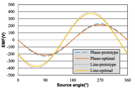
Comparison of EMF waveforms.
Since less PMs are utilized in the optimal rotor, the electromotive force (EMF) of the machine is lower, as shown in Fig. 10. It also can be seen that the optimal structure can achieve the same perfect EMF waveforms as the prototype. The main electromagnetic parameters are also calculated by FEA as shown in Table 6. To maintain the same output torque, a further increase of the current is required.
Main parameters of prototype and machine with optimal sleeve
The maximum allowed compressive strength of Sm2Co17 is 800 MPa. The segmented PMs mainly sustain the compressive stress, regardless of their safety. Care should be taken to the safety of the inner cylindrical PM. The static interference fit size between the cylindrical PM and the sleeve is 0.08 mm, which is nearly half the size of that in the prototype. The maximum stress of the sleeve at the static state is 708.69 MPa, which is smaller than that (791.87 MPa) in the prototype. The smaller the static stress between sleeve and PM, the lower risk of cracking at PM axial ends during the assembly process [22].
Figure 11 shows the Von-Mises stress of the sleeve and F s of the inner cylindrical PM at the working state of 40000 r/min, 220 °C. The maximum Von-Mises stress of the sleeve is 602.50 MPa occurring around the strengthening ribs. The PM has a high value of F s . Figure 12 shows the sleeve Von-Mises stress as well as F s of PM versus rotor’s rotating speed at working temperature 220 °C. In both machines, the maximum stresses in sleeves increase slightly with the increase of the rotor’s rotating speed due to the variation of the dynamic interference fit size. However, the F s of PM in the prototype decreases to around 1.0 at speed 44000 r/min. In contrast, the optimal sleeve can ensure the safety of the rotor working at the speed of 62500 r/min. The optimal sleeve has well balanced protective effect to the PM, with a resultant increase in maximum working speed of nearly 40% with respect to the prototype.
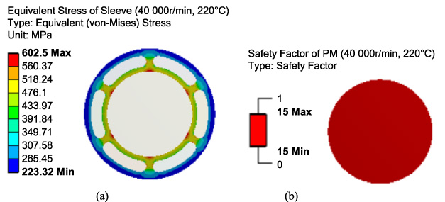
Analysis of rotor strength (40000 r/min, 220 °C). (a) Von-Mises distribution of sleeve. (b) Safety factor distribution of PM.
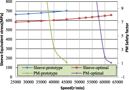
Variation of sleeve Von-Mises stress and PM F s (220 °C).
For the given maximum rotating speed 44000 r/min, the impact on the safety factors as the working temperatures are varied is shown in Table 7. The sleeve in the prototype has well protective effect to the PM at temperatures below 140 °C, while the optimal sleeve has well balanced protective effect to the PM in the working temperature range from 20 °C to 340 °C. Furthermore, both F s of the sleeve and the PM in the optimal rotor are higher. The mechanical strength of the rotor with the optimal structure is enhanced tremendously.
Safety factors comparison between the prototype and machine with optimal sleeve (44000 r/min)
The design of a HSPMSM is a complex task, including magnetic, thermal, mechanical, and rotor dynamic considerations. Mechanical design is a critical aspect. This paper has focused on the mechanical analysis of metallic sleeve in HSPSMS.
In traditional HSPMSM, the metallic sleeves have unbalanced protective effect on the PMs. On one hand, the protective effect of the sleeve will be changed with the change of working states. The sleeve will endure a higher stress if the startup process is very quick, therefore the preheating process is needed. The PM is at the highest risk of cracking when the machine is working at the high temperature and the high rotating speed conditions, though the sleeve has a higher value of F s . On the other, for the long and thin high-speed rotor, it has a non-homogeneous temperature distribution along the axial direction. The dynamic interference fit sizes as well as the dynamic pressures are different between the two sides of the rotor due to the non-homogeneous temperature distribution. The protective effect of the sleeve is different on both sides.
The interference fit between sleeve and PM in traditional high-speed rotors will be greatly changed due to thermal expansion and centrifugal force, this is the root cause of the unbalanced protective effect of sleeves. This is also the reason of the underutilization of the materials of both sleeves and PMs.
With comprehensive consideration of the protective effect of the metallic sleeve used in high-speed machines, requirements are summarized as follows: (1) the needed static interference fit size is smaller; and (2) the variation of the interference fit is affected slightly by the temperature and the rotor’s rotating speed.