
Abstract
This paper presents a triple three-phase permanent magnet synchronous motor (PMSM) with shaped magnets for low vibration applications. Firstly, the features of the designed PMSM are investigated from three aspects, including triple three-phase windings, shaped magnets, and multi-layered housing. Then, the armature reaction, magnetomotive force, torque performance, and fault tolerance ability of the designed PMSM are investigated. Subsequently, the radial force of the designed PMSM with shaped magnets is studied, in which the radial force modulation effect is considered. In addition, the radial force and vibration reduction principle is elaborated in detail. The modal simulation and experiment are carried out, and the vibration reduction effect of the designed PMSM is verified by the multiphysics vibration predicted model. The result shows that the vibration can be effectively reduced by the shaped magnets and multi-layered housing design, and the output torque of the designed PMSM has been reduced insignificantly thanks to the triple three-phase windings.
Keywords
Introduction
Permanent magnet (PM) synchronous motors (PMSMs) have gained wide applications in electric propulsion and servo systems [1–3]. In the past several decades, great efforts have been made into its high-power density, high efficiency, and excellent torque performance [4–7]. However, due to the usage of high remanence materials and the demand for lightweight, the radial force and vibration response of PMSMs have become particularly severe [8–11].
The vibration response of PMSM mainly results from the air-gap radial electromagnetic force [12–14]. The motor vibration displacement is approximately inversely proportional to the fourth power of the radial force order [15–17]. Therefore, the low-order radial force harmonics have a greater contribution than high-order ones to motor vibrations, while the high-order radial force harmonics are usually neglected. Recently, it was pointed out in [18–20] that the high-order radial force also induces large vibrations in fractional-slot PMSMs due to the radial force modulation effect. Afterward, the investigation of the radial force modulation effect was expanded to the integral-slot PMSMs [21–23]. It was found that the slot number order radial force also results in 0th-order vibration with a large amplitude. The modulated radial force harmonics even contribute more to vibration response than that of the original ones. Therefore, due to the radial force modulation effect, high-order radial force harmonics of PMSMs should also be paid more attention.
High-order radial force harmonics are mainly generated by the fundamental component and harmonics of PM flux density. The shape of the magnet in the design of an electric motor is more effective in reducing the PM flux density harmonics [24,25]. With the decrease of the flux density harmonics, the corresponding radial force harmonics will be also restrained. In addition to the flux density harmonics, the shaped magnet design is an effective way to reduce the cogging torque and torque ripple. However, the radial force and vibration performance of fractional-slot concentrated-winding PMSMs deteriorated due to the reduction of the flux density harmonics [20]. Therefore, the vibration response of fractional-slot concentrated-winding PMSMs will be worsened if the shaped magnet design is adopted. However, the effects of shaped magnet design on the slot number order radial force and vibration response of the designed integral-slot PMSM are still not thoroughly studied yet. In addition, the shaped magnet design is usually used to reduce cogging torque and torque ripple of the PMSMs. It will also sacrifice some electromagnetic performance of the PMSMs [26]. Therefore, a triple three-phase windings structure is designed to compensate for the sacrificial electromagnetic performance. In addition, the fault-tolerance performance of the designed PMSM with the triple three-phase windings will also be evaluated.
In this paper, a triple three-phase PMSM with shaped magnets for low vibration applications will be designed, and its electromagnetic performance and vibration reduction principle will be investigated. Firstly, the features of the designed PMSM will be introduced in three aspects, including triple three-phase windings, shaped magnets, and layered housing in Section 2. Subsequently, the armature reaction magnetomotive force (MMF), torque performance, and fault tolerance ability of the designed PMSM will be investigated in Section 3. Then, the radial force of the designed PMSM with shaped magnets will be studied, and the reduction principle of radial force will be elaborated in Section 4. Afterward, the modal simulation and experiment will be carried out, and the vibration reduction of the designed PMSM will be verified by the multiphysics vibration predicted model in Section 5.
Features of designed PMSM
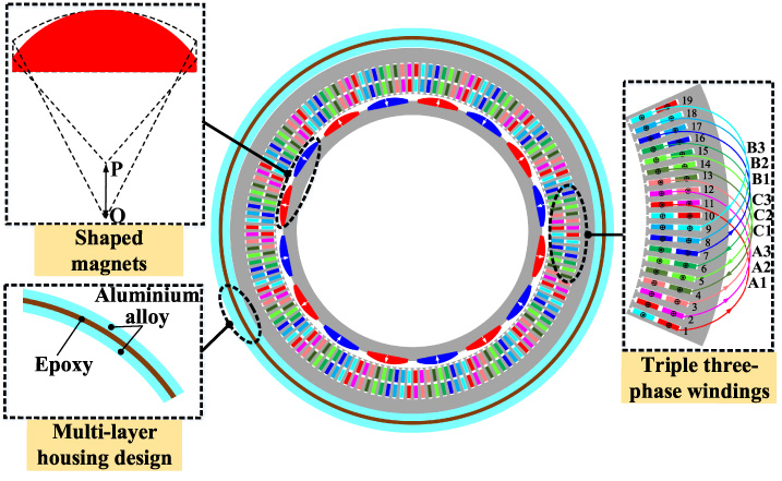
Figure 1 shows the 2D cross-sectional view of the designed PMSM. The designed PMSM adopts the integral-slot windings, and the slot-pole combination is 144-slot/8-pole. One of the most obvious features of the designed PMSM is the triple three-phase windings structure. In addition, the shaped magnet design is adopted to reduce the magnetic field harmonics and electromagnetic vibration. The shaped magnet design is realized by changing the center position of the outer diameter of each magnet. Furthermore, to prevent electromagnetic vibration from radiating excessive electromagnetic noise through the housing, a multi-layered housing design is proposed to suppress the vibration on the housing surface. The housing of the designed PMSM is divided into three layers; the inner and outer layers are made of aluminum alloy, and the middle layer is filled with epoxy material. The main parameters of the designed PMSM are listed in Table 1. The rated power and rotation speeds are 40 kW and 400 r/min, respectively. In addition, the B–H curve of electric steel is shown in Fig. 2.
2D cross-sectional view of designed PMSM.

B–H curve of electric steel.
Main parameters of designed PMSM
MMF derivation
Figure 3 shows the slot electric potential star diagram of the three-phase and triple three-phase PMSMs. It can be seen that each phase of the three-phase windings is composed of 6 vectors. The triple three-phase windings are generated by inversely connecting two vectors with opposite phases in series. The triple three-phase windings are divided into three independent three-phase windings in the designed PMSM. Since there is no distribution effect in the triple three-phase windings, its windings factor is greater than that of the conventional three-phase winding, which will undoubtedly increase the power density of the designed PMSM.
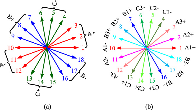
Slot electric potential star diagram. (a) Three-phase windings. (b) Triple three-phase windings.
Compared with that of the conventional three-phase PMSM, some armature reaction MMF harmonics of the designed triple three-phase PMSM will be eliminated. Since each set of three-phase windings is symmetrical, the windings functions of one set of three-phases can be expressed as
Substituting (1) and (2) into (3), the armature reaction MMF equation of the triple three-phase PMSM can be derived as
For the conventional three-phase PMSM with even number slots, the harmonic orders of armature reactive MMF are (6k ± 1)p. According to (4), most of the MMF harmonics are eliminated for the designed triple three-phase PMSM, and the rest are (18k ± 1)pth-order MMF harmonics. Figure 4 shows the armature reactive MMF spectrums of the three-phase and triple three-phase PMSMs. The triple three-phase windings structure eliminates 24th-order, 40th-order, 56th-order, 88th-order, and 104th-order MMF harmonics. In addition, the winding factor of the three-phase PMSM is 0.96, while that of the triple three-phase PMSM is 1. Therefore, as shown in Fig. 4, the 8th-order working MMF harmonic amplitude of the triple three-phase PMSM is larger than that of the conventional one, which will increase the torque density of the PMSM.

MMF spectrums of three-phase and triple three-phase PMSMs.
Figure 5 shows the torque waveform of each set of three-phase windings and the synthetic torque waveform. It can be seen that each set of three-phase windings pulsates 6 times on an electric cycle. Interestingly, the three sets of three-phase windings have a spatial phase difference of pi/6 rad. Therefore, the 6th-order harmonic of the synthetic torque of the designed triple three-phase PMSM can be canceled out. Figure 6 shows the torque comparison of the three-phase and triple three-phase of PMSMs. It can be seen that the torque ripple of the three-phase PMSM is greatly reduced by the triple three-phase windings. In addition, since the winding factor of the triple three-phase PMSM is greater than that of the conventional three-phase one, the average torque of the triple three-phase PMSM is greater than that of the three-phase counterpart. The average torque of the three-phase and triple three-phase PMSMs are 962 Nm and 1002 Nm. The torque ripple of the three-phase and triple three-phase PMSMs are 7.1% and 2.9%, respectively.
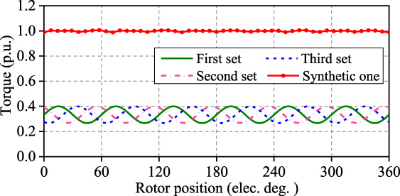
Torque separation of designed PMSM.
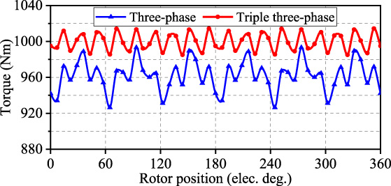
Torque comparison of three-phase and triple three-phase PMSMs.
Another advantage of the designed triple three-phase PMSM is high reliability. Figure 7 shows the driving circuit and current vector diagram under the one-phase open-circuit fault condition. When an open-circuit fault in a one-phase winding is detected, this set of three-phase winding will be cut off. In this case, the operation mode of the triple three-phase PMSM will be switched to that of a dual three-phase PMSM.
Figure 8 shows the torque variation under different working conditions. When the designed triple three-phase PMSM is under the one-phase open-circuit fault condition, one set of the three-phase windings will be cut off. The average output torque of the PMSM is reduced to two-thirds of that under normal operating conditions. In addition, by adjusting the amplitude and phase of the output current in the rest of the two sets of the three-phase windings, the output torque of the PMSM can be increased to the rated torque level, but the torque ripple increases to 3.4%. However, for the conventional three-phase PMSM, when a one-phase open-circuit fault occurs, the output torque of the three-phase PMSM cannot maintain the torque performance before the fault.
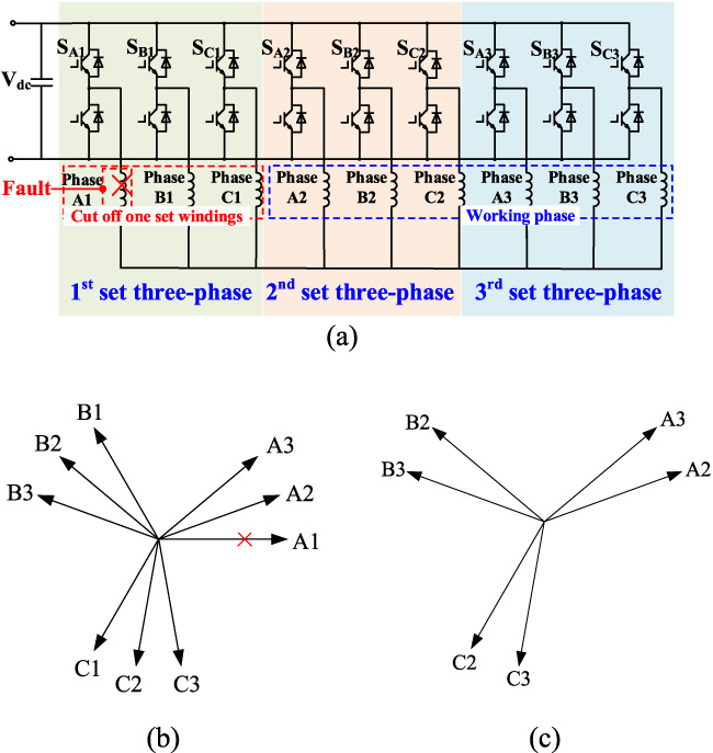
Fault-tolerant operation diagram. (a) Driving circuit diagram. (b) One-phase open-circuit fault conditions. (c) Cutting off one set of three-phase windings.

Torque variation under different working conditions.
Radial force derivation
The vibration performance is an increasingly important indicator for PMSMs. The radial force is the main reason for the vibration generation of low-speed PMSMs. According to the Maxwell stress equation, the radial force is produced by the interaction between different air-gap magnetic field harmonics. The radial force can be expressed as
The radial flux density contains two parts when the saturation of the magnetic field is ignored. It can be written as
Substituting (8)–(10) into (5), the radial force density can be expressed as
According to the flux density harmonic sources, the radial force can be divided into three categories, (i.e.,
Categories of radial force harmonics
Figure 9 shows the shaped magnet design diagram of the PMSM. The shaped magnet design is usually adopted to reduce the cogging torque and torque ripple. In this paper, the shaped magnet design is adopted to reduce the radial force and electromagnetic vibration of the PMSM.
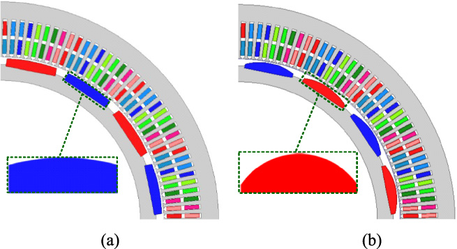
Magnets of two PMSMs. (a) Conventional one. (b) Shaped one.
Since the designed PMSM has the integral-slot windings structure, its vibration responses are mainly excited by the 0th-order radial force. In the designed PMSM, the 0th-order radial force can be divided into two types. The first type of the 0th-order radial force is generated by the interaction of the flux density harmonic itself. Due to the same order and frequency, these radial force harmonics generated by the same flux density harmonics are 0th-order with 0-frequency. It is worth emphasizing that this kind of 0th-order radial force has an insignificant effect on the motor vibration response. The second type of the 0th-order radial force is generated by the interaction of two different flux density harmonics. This type of 0th-order radial force is modulated by the Qth-order radial force. Figure 10 shows the radial force modulation process. Since the number of slots and the spatial order of the Qth-order radial force is equal, the magnitude of the radial force on each stator tooth is equal. It means that the Qth-order radial force can be modulated to the 0th-order radial force through the modulation of stator slots.

Radial force modulation process.
Both the fundamental and harmonic orders of the PM flux density of the designed PMSM can be expressed as (2k −1)p. Therefore, it can be inferred from (11) and Table 2 that the radial force orders of the integral-slot PMSMs are 2kp. When 2kp = Q, the 2kpth-order radial force will be modulated to 0th-order radial force. The fundamental frequency of the PMSM is f e , so the frequency of 2kpth-order radial force is 2kf e . Therefore, the frequency of the modulated 0th-order radial forces is (Q∕p)f e due to 2kp = Q.
The Qth-order radial force is mainly generated by the flux density harmonics combinations, such as (p, Q − p), (3p, Q − 3p), (5p, Q − 5p) … ((2k −1)p, (Q−(2k −1)p)). The phase angles between adjacent PM flux density harmonics are π rad. Therefore, regardless of the initial phase angle of the fundamental flux density, the phase angles of each Qth-order radial force generated by the PM flux density combinations are definite. In a summary, all PM flux density harmonics contribute to the total Qth-order radial force, and the shaped magnet design with low harmonics content is beneficial to reduce the Qth-order radial force.
The radial force harmonics and output torque performance are the two main considerations in the design of the shaped magnets. The lower radial force harmonics and higher average output torque should be taken into account. Figure 11 shows the average torque and 144th-order radial force vary with the eccentricity of the magnets. It can be seen that when the eccentricity of the magnets is greater than 60 mm, the average torque decreases greatly, but the 144th-order radial force does not decrease significantly. Therefore, the magnet eccentricity is finally determined to be 60 mm to obtain better torque and lower radial force amplitude.

Average torque and radial force vary with eccentricities of magnets.
Figure 12 shows the flux density waveforms and spectrums of PMSMs with conventional magnets and shaped magnets. The flux density waveform of the PMSM with shaped magnets is more sinusoidal than that with the conventional one. Also, it can be seen that the flux density harmonic component is weakened by shaped magnets. In particular, the 24th-order harmonic flux density is significantly reduced. However, since the magnet usage of the shaped PMSM is lower than that of the conventional PMSM, the amplitude of fundamental flux density harmonics of the shaped PMSM decreases by 13.4% compared with that of the conventional PMSM.
Figure 13 shows the radial force spectrums of the designed PMSMs with conventional and shaped magnets. Compared with that of the PMSM with conventional magnets, the amplitude of the 144th-order radial force has been effectively reduced, and it was decreased by 34.7%. It is verified that the shaped magnet design is effective in reducing the Qth-order radial force, which has a significant impact on the vibration response. In addition, the 32nd- and 48th-order radial force harmonics decreased by 83.8% and 93.4% respectively. The 16th-order radial force harmonic increased by 23.1%, but it has limited influence on the vibration performance of the PMSM.
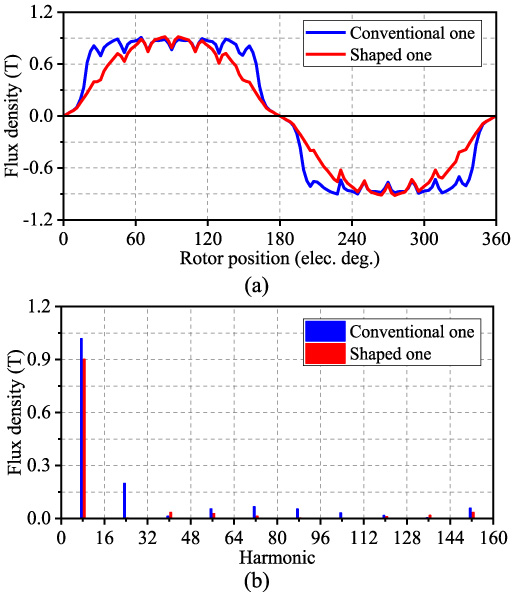
Flux density of conventional and shaped PMSMs. (a) Waveform. (b) Spectrum.

Radial force density comparison between conventional and shaped PMSMs.
Figure 14 compares the cogging torque and output torque performance between conventional and shaped PMSMs. The peak–peak value of the cogging torque for the conventional and shaped PMSMs are 30.2 Nm and 2.2 Nm, respectively. The output torque ripple of the conventional and shaped PMSMs are 3.4% and 0.3%, respectively. Since the shaped PMSM has less magnet usage than the conventional PMSM, its average output torque is lower than that of the conventional one. Thanks to the triple three-phase winding structure of the designed PMSM, its average torque is only reduced by 1.2% compared with the three-phase conventional PMSM.
The shaped magnet design has a great effect on reducing flux density harmonics and radial force harmonics, and the vibration reduction effect will be validated in the next section. However, the shaped magnet design has the defect of sacrificing the fundamental magnetic field, i.e., the 8th-order flux density harmonic, as shown in Fig. 12(b), and it will reduce the output torque of the PMSM. The triple three-phase windings design can improve the output torque of the PMSM, as shown in Fig. 6. Combining the triple three-phase design with the shaped magnet design can reduce the vibration of the PMSM, and ensure that the PMSM has good torque performance.
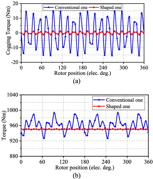
Torque performance comparison between conventional and shaped PMSM. (a) Cogging torque. (b) Output torque.
Modal analysis
Figure 15 shows the prototype and modal test devices of the designed PMSM. The shaped magnet, stator, and stator with windings are shown in Figs 15(a), 15(b), 15(c), respectively. The modal test of the stator assembly is carried out to obtain the natural frequencies for the designed PMSM. The PMSM is placed on a soft elastic material to simulate an unconstrained state as shown in Fig. 15(d). The hammering method is adopted in this modal test. By hammering multiple positions on the motor surface and picking up the corresponding vibration data, the frequency response function of the motor structure is obtained as shown in Fig. 16. As seen, there is a peak value of the frequency response function at 625.2 Hz, which is in good agreement with the simulation results of the 2nd-order modal frequency at 617 Hz listed in Table 3. Table 3 lists the simulated and tested modal parameters of the designed PMSM. It can be seen that the simulation results are in good agreement with the test results, which provides a guarantee of the accuracy of vibration simulation.
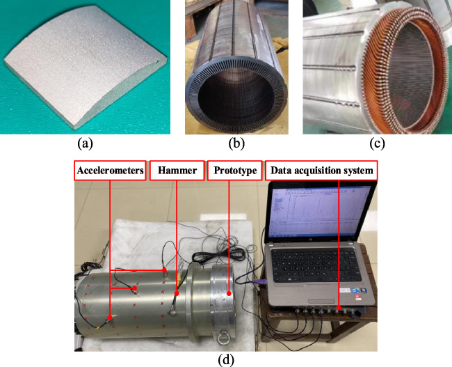
Prototype and modal test device. (a) Shaped magnet. (b) Stator. (c) Stator with windings. (d) Modal test.

Frequency response function of designed PMSM.
Modal parameters of designed PMSM
In addition, it should be noted that the parameters of anisotropic materials in modal simulation are obtained from modal experiments. The equivalent material parameters can be obtained by adjusting the parameters in the finite-element model to approximate the modal test results. The equivalent material parameters of the stator core, windings, housing, and the epoxy material between two layers of housing are given in Table 4.
Equivalent material properties
Figure 17 shows the flow chart of the multiphysics vibration simulation. The multiphysics vibration predicted model contains three parts, namely the electromagnetic force calculation module, modal analysis module, and the vibration calculation module. During the simulation process of modal analysis and vibration response, the modal damping is usually obtained by experience, and accuracy is relatively low. However, the modal damping and orthotropic material parameters have been obtained by the modal test. In addition, modal parameter acquisition is an important step to realizing high accuracy simulation of motor vibration. The electromagnetic force and structural modes are calculated by the finite-element method, and the modal superposition method is adopted to calculate the vibration response of the designed PMSM.

Flow chart of multiphysics vibration simulation.
Figure 18 shows the vibration acceleration comparison between conventional and shaped PMSMs. It can be seen from Fig. 18 that the main vibration peaks appear at even multiple electrical frequencies. As mentioned above, the largest factor for the vibration of the designed PMSM is the 144th-order radial force, and its frequency is 18f e . Compared with the conventional PMSM, the vibration acceleration of the designed PMSM with the shaped magnet is significantly reduced.
Figure 19 shows the vibration acceleration comparison between two PMSMs with single-layer and multi-layer housing structures. Since the middle layer of the multi-layer housing structure is made of epoxy material, it can effectively inhibit vibration transmission. Therefore, the multi-layer structure can further reduce the vibration response of the designed PMSM.

Vibration acceleration comparison between conventional and shaped PMSMs.

Vibration acceleration comparison between two PMSMs with single-layer and multi-layer housing structures.
In this paper, a triple three-phase PMSM with shaped magnets has been designed for low vibration applications. The designed PMSM has the characteristics of triple three-phase windings, shaped magnets, and layered housing. The output torque and fault tolerance ability have been improved by the triple three-phase structure. Then, the radial force of the designed PMSM with shaped magnets has been investigated, and the Qth-order radial force has been reduced by the shaped magnet design. In addition, the sacrificed output torque due to the shaped magnet design is compensated by the triple three-phase windings. Afterward, the modal simulation and test were carried out, and the vibration reduction effect of the designed PMSM has been verified by the multiphysics vibration simulation model. The results show that the vibration response has been effectively suppressed by the shaped magnets and the multi-layer housing design.
Footnotes
Acknowledgements
This work was supported in part by the National Natural Science Foundation of China under grants 51977099.