
Abstract
The traditional displacement sensors used in the bearingless induction motors (BIM) have many disadvantages, such as high cost, poor temperature stability, low conversion efficiency and complex motor operation. To improve these disadvantages, the detailed study on the novel displacement sensorless control based on the model reference adaptive system (MRAS) is presented in this paper. Firstly, the principle of radial suspension force generation and the mathematical model of the BIM are introduced. Secondly, the basic structure of the proposed MRAS is constructed and the stability is verified by the Popov’s integral inequality. Thirdly, to improve the control accuracy and dynamic characteristics of sensorless vector control system, a method of directly controlling rotor eccentric displacement by using suspension force compensation is proposed. Finally, the feasibility and accuracy of the proposed method have been verified by the simulation and experimental results. According to the results obtained, the radial displacement of the rotor can be accurately estimated, and the rotor displacement sensorless control of the BIM based on MRAS is achieved.
Keywords
Introduction
The bearingless induction motor is a new type of motor with high performance that utilizes the Maxwell force generated by the two sets of windings in the stator of the motor to suspend the rotor [1–5]. Because of the incomparable advantages of the small size, low cost, no friction and high power, and low energy consumption, the wide application and important scientific significance of the BIM have been shown in aerospace, flywheel energy storage system, nuclear reactor and many other industrial fields [6–11]. Similarly, bearingless permanent magnet motors [12–24] and bearingless switched reluctance motors [25–35] have been widely used in practice according to their own characteristics. To control the suspension force of the BIM stably, the accurate estimation of the rotor radial displacement is necessary [36–45]. Currently, the eddy current displacement sensors are widely used in the bearingless induction motor because of excellent performance. However, eddy current displacement sensors also have disadvantages, such as poor temperature stability, high noise and small linearization range. The size and complexity of the BIM will be also affected by these drawbacks. Therefore, the study of rotor displacement-sensorless control method for the BIM based on the MRAS is essential [46–48].
For the traditional rotor radial displacement self-sensing method used in the BIM, according to the basic principle of sensorless technology, it can be divided into two types: the method based on signal injection [49–52] and rotor salient pole detection, and the method based on back electromotive force or magnetic flux detection. These two methods are applicable to different situations according to their different principles. The method based on back electromotive force or magnetic flux detection is suitable for the high-speed operation of the motor. However, when the motor is running at a low speed, the amplitude of the counter electromotive force becomes smaller, which causes the position signal of sensorless control to be relatively small. The method based on signal injection and rotor salient pole detection performs better at low speed operation because the excitation is an applied signal that does not change with speed. However, when extra signals are injected, it will inevitably affect the normal operation of the motor and reduce the operating efficiency of the motor. Therefore, the method based on back electromotive force or magnetic flux detection is still the first choice when the motor is running at high speed. At present, this method mainly includes model reference adaptive system (MRAS), extended kalman filter (EKF), and sliding mode observer (SMO). In literature [53,54], the model reference adaptive method based on reactive power is proposed, which proves that the system has high stability, and the prediction accuracy and dynamic performance of the system are significantly improved. In literature [55], a nonlinear extended kalman filter observer is proposed to solve the problem that the large amount of computation is caused by the addition of stator electrical group values to the extended kalman filter observer. In literature [56], the sliding mode observer is based on the stator voltage equation in the static coordinate system, and the deviation between the current of the observer and the actual current is selected as the sliding mode surface to estimate the equivalent counter electromotive force, and then the rotor position in the counter electromotive force is obtained by the algorithm.
In this paper, a novel rotor displacement sensorless control based on MRAS method for the BIM is proposed. The outline of this paper is as follows: the principle and mathematical model of the BIM are described in the second part. In the third part, the rotor radial displacement self-sensing method of the BIM based on MRAS are obtained. In the fourth part, a method of directly controlling rotor eccentric displacement by using suspension force compensation is set up. Finally, the simulation and experiment have been presented to prove the effectiveness of the proposed method.
Operating principle and proposed scheme
The principle of radial suspension force generation
To achieve the stable operation of suspension system, the BIM needs to add the windings that control the radial force stably. Therefore, a set of suspension windings is added to the stator windings of the common induction motor. The two sets of windings are p 1 pole pair and p 2 pole pair respectively. The p 1-pole stator windings can be used to generate the rotating magnetic field. They are called torque windings. After energization in the p 2-pole stator windings, the controlled suspension force can be generated to suspend the rotor. The p 2-pole stator windings are called suspension force windings. To obtain the stable operation of the BIM, the controlled radial suspension force can be generated when two sets of windings satisfy the following conditions: (1) p 2 = p 1 ± 1, (2) the currents in two sets of windings have the same electrical angle frequency.
According to the electromagnetic theory, if the rotor of the motor is deviated from the axis of the stator of the motor by the external pulling force, the distribution of the flux density of the motor will be unbalanced. At this time, the Maxwell force is pointed to the direction of the rotor deviation, and the size is not zero. If external pulling force is removed, the rotor cannot return to the original position by the inherent magnetic pulling force. Therefore, it is necessary to change the distribution of the original magnetic field to generate the Maxwell force by controlling the suspension force windings. The principle of radial suspension force generation is shown in Fig. 1. The currents flowing into torque windings and suspension force windings are i 1 and i 2 and flux linages 𝜓1 and −𝜓2 are generated respectively. When the currents flowing into windings in the direction are shown in Fig. 1(a), the direction of the upper fluxes 𝜓1 and 𝜓2 is the same, the air gap flux density is increased, and the lower fluxes 𝜓1 and 𝜓2 are opposite in direction, so the air gap flux density is decreased. The radial suspension force F y is generated in the positive direction along the y-axis. If the direction of current flowing into the suspension force windings is reversed, the radial suspension force can be generated in the opposite direction of y. The radial suspension force along the x-axis direction is generated as shown in Fig. 1(b). The direction of the currents i 2 of suspension force windings in Fig. 1(b) is perpendicular to the direction of the currents i 1 of suspension force windings in Fig. 1(a).
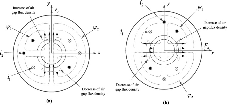
Principle of radial suspension force generation.
Because of the rotor eccentric displacement, there are mutual inductances between the torque windings and the suspension force windings. These mutual inductances indicate the coupling between the torque and the suspension force, and they are proportional to the rotor radial displacement. Therefore, the mathematical modeling of the BIM is essential to realize the decoupling of rotor radial suspension and the torque of the BIM completely [57].
The flux linkage equation [58] for BIM can be expressed as
The d and q-axis voltage equation [59–64] for the torque windings and suspension force windings of the BIM can be expressed as
According to the Maxwell tensor method [65–69], the x and y axis components of the radial suspension forces F
x
and F
y
can be expressed as
The estimation method based on MRAS
As shown in the Fig. 2(a), the basic structure of the MRAS contains two models. One is the adjustable model and the other is the reference model. They compute the actual currents and estimated currents of the suspension force windings respectively. The output physical quantities of the models are the same. The adjustable model is dependent of the parameters to be observed. The error signal of two models is fed to the inputs of the adaptation mechanism module, which yields estimated rotor radial displacements. In Fig. 2(b), the equivalent nonlinear feedback system of the MRAS is satisfies Popov’s hyperstability theory. The stability of the proposed MRAS can be confirmed. The equivalent structure of the proposed scheme includes liner block and non-liner time-varying block [70–72].
The d and q-axis voltages for the suspension force windings of the BIM can be written in a matrix form as
Equation (5) containing the actual current of suspension force windings is used as the reference model. According to (5), the adjustable model can be expressed as
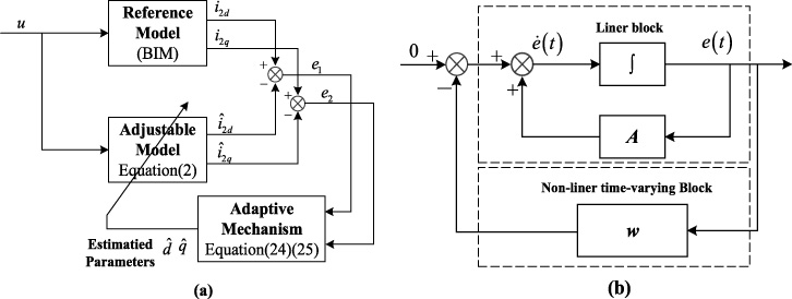
(a) Basic structure of the MRAS. (b) Equivalent structure of the proposed MRAS.
The generalized error of the MRAS is expressed as
The derivative of the generalized error is
As shown in Fig. 2(b), the stability characteristics of the equivalent nonlinear feedback scheme of the MRAS is determined by the concept of Popov’s hyperstability theory. If the system satisfies following two conditions, the feedback system will be globally stable.
(1) Ensure that the transfer function H = (sI − A)−1 of the linear stationary block is a strictly positive real function.
(2) The nonlinear feedback block satisfies the Popov’s integral inequality.
According to [73–75], H is a strictly positive matrix, the condition (1) is satisfied. The verification of condition (2) is as follows
Substituting (7) and (9) into 𝜂 (0, t
1), the 𝜂 (0, t
1) can be expressed as
Assume that
Therefore, the verification of (10) is converted into verification of
Taking the verification of
Substitute (14) into 𝜂1(0, t
1)
Assume that
Substituting (17) and (18) into (16), the expression of 𝜂11(0, t
1) reduces to
According the well-known inequality, it can be shown that
Assume that
Substituting (22) into (21), it can be shown that
According to (20) and (23),
In the same way, the adaptive mechanism of
The rotor radial displacements x and y are given by
According to (24) and (25), the estimated rotor radial displacement [76–81] is determined by dq-axis components of currents of the torque windings, derivative of mutual inductance with regard to the rotor radial displacements and the self-inductance of the suspension force windings.
In contrast with using the displacement signal obtained by the traditional gap sensors as the feedback, the dynamic performance will decrease by using the proposed suspension force sensorless control system because of error and delay of the rotor radial displacement signal. Typically, traditional suspension force control system of the BIM is an indirect vector control method. However, the actual control performance is hard to achieve the results of theoretical analysis because of the variation of vector coordinates. The accuracy and dynamic performance of the suspension force control are influenced by the open-loop and indirect suspension force control method [82–87]. To improve the drawback of sensorless vector control system, a method of directly controlling rotor eccentric displacement by using suspension force compensation is proposed.
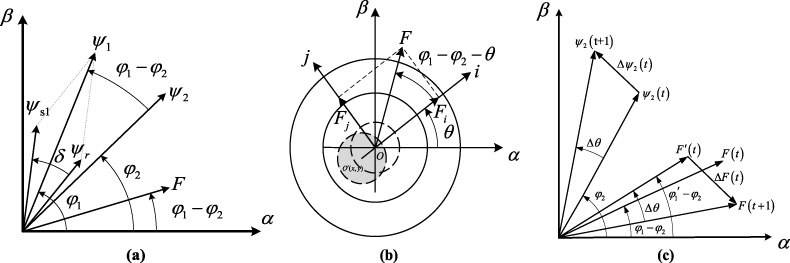
(a) Vector diagram of direct suspension force control. (b) Suspension force in rotor eccentricity displacement coordinate (c) Vector diagram of the suspension force and flux linkage.
The 𝛼-𝛽 axis components of the radial suspension forces F
𝛼 and F
𝛽 can be written as
In Fig. 3(b), the suspension force F is analyzed from the 𝛼-𝛽 coordinate to the eccentricity displacement coordinate. Then the controllable radial suspension force component F
i
and F
j
in rotor eccentricity displacement coordinate can be expressed as
The orientation of the eccentricity displacement is given by
According to (28), suspension force is equivalent to the space vector with the magnitude of k m 𝜓1𝜓2 and the phases of the flux linkages of the suspension force windings and torque windings resultant air-gap flux linkage. Since the mechanical time constant of the BIM is much larger than the electrical time constant, the small signal model analysis method can be used. Assuming the rotor position is stationary in a very small period Δt, the relationship between the radial suspension force and the flux linkage of the suspension force windings and their electromagnetic torque is analyzed.
(1) When the motor load torque is constant in steady state operation, the amplitude 𝜓1 and phase φ1 of the torque windings resultant air-gap flux linkage and the angle δ of the torque windings flux linkage and the rotor flux linkage keep constant within Δt. According to (28), the suspension force is determined by the amplitude 𝜓2 and the phase φ2 of the suspension force windings.
(2) When the motor is in the dynamic operation of variable torque, 𝜓 s1 and 𝜓 r keep contrast, and the variation of torque is realized by controlling the magnitude of δ. Assuming that the electromagnetic torque increases within a certain range, and it is determined by increase of the angle δ, which inevitably causes the amplitude 𝜓1 of torque windings resultant air-gap flux linkage to decrease and the phase φ1 to increase. At the same time, the amplitude and phase of the rotor radial suspension force are also decreasing. In this case, it is necessary to increase the amplitude 𝜓2 and phase φ2 of the suspension force windings flux linkage to compensate the radial suspension force. When the electromagnetic torque is reduced, the opposite is true.
Therefore, the basic idea of the direct suspension force compensation control of the BIM is shown as follow [88–91]: when the torque increases, based on the precise calculation of the amplitude 𝜓1 and the phase φ1 of torque windings resultant air-gap flux linkage, the stable controllable radial suspension force of the BIM can be realized by controlling the amplitude 𝜓2 and phase φ2 of the flux linkage of the suspension force windings. The variation of the rotor radial suspension force and the flux linkage of the suspension force winding from t to t + 1 can be seen from the Fig. 3(c). At time t + 1, the amplitude of suspension force windings flux linkage is 𝜓2(t + 1). It is assumed that the electromagnetic torque increases ΔT
e
during the period from time t to time t + 1, which causes the amplitude of torque windings resultant air-gap flux linkage decrease from 𝜓1(t) to
Subtracting (30) from (31), the expression for the variation of the suspension force component in the rotor eccentric displacement coordinate can be got as follows:
Expressed in the form of a matrix
According to (33), based on the precise calculation of the amplitude and phase of the torque windings resultant air-gap flux linkage, to keep the suspension force stationary, it is essential to control suspension force windings flux linages Δ𝜓2i and Δ𝜓2j in the rotor eccentricity displacement coordinate. Therefore, to achieve the suspension force winding flux linkage control, it is necessary to obtain the method for the precise flux observation.
According to the voltage-current model of the BIM, the 𝛼𝛽-axis flux linkage of torque windings can be given as
Assume that the leakage inductance of the torque windings is L
1δ. The torque windings resultant air-gap flux linkage in the 𝛼-𝛽 coordinate are given as
The amplitude 𝜓1 and phase φ1 of torque windings resultant air-gap flux linkage in the 𝛼-𝛽 coordinate can be expressed as
In the same way as described for the torque windings resultant air-gap flux linkage, the 𝛼-𝛽 axis flux linage of the suspension force windings can be written as
The amplitude 𝜓2 and phase φ2 of the suspension force windings flux linkage are given as
The whole suspension force sensorless control system of the BIM is shown in Fig. 4.
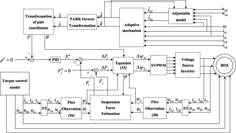
The block diagram of the MRAS-based suspension force sensorless control system.
To verify the effectiveness of the proposed MRAS-based suspension force sensorless control system of the BIM and the proposed suspension force control strategy. The MATLAB/SIMULINK was used to simulate the IFO-controlled BIM driver. The BIM parameters are given in Table 1. The initial values of rotor radial displacement are x (0) = 0 mm and y (0) = −0.2 mm, respectively.
BIM parametes
BIM parametes
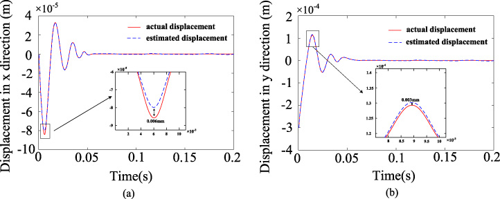
(a) Actual and estimated rotor radial displacement waveforms using the proposed suspension force control strategy in the x-direction. (b) Actual and estimated rotor radial displacement waveforms using the proposed suspension force control strategy in the y-direction.
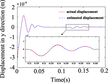
Actual and estimated rotor radial displacement waveforms in the y-direction with a sudden suspension force load change.
When the three-phase sinusoidal currents are applied into the torque windings, the BIM rotates at certain speed. According to the feedback signal of the rotor eccentric displacement which are obtained by the proposed MRAS-based suspension force sensorless control system, an appropriate current is applied in the suspension force windings to overcome the influence of the rotor gravity, unilateral magnetic force and centrifugal force generated during the rotation, so that the rotor is maintained in a balanced position and the stable suspension.
In Fig. 5, the curves of the actual displacement and estimated displacement obtained by the proposed MRAS-based method are shown. From Fig. 5(a) and (b), it is seen that the maximum errors between actual and estimated displacements are 0.006 mm and 0.003 mm, respectively. The auxiliary bearing air gap length 0.3 mm is much bigger than the maximum error. Therefore, the accuracy of rotor radial displacement using the proposed MRAS-based self-sensing method is verified.
In order to further study the control performance, the suspension force load disturbance of 5 N in the y-direction is applied to the BIM system, and the simulation results of estimated rotor displacement and actual rotor displacement are shown in Fig. 6. After the suspension force load disturbance is applied to the shaft, the rotor radial displacement drops abruptly to −14 m in the y-direction and then returns to the balanced position after 40 ms. From the comparative results, we can see that the estimated displacement is also in accordance with the actual displacement exactly. Therefore, the estimated results measured by the proposed MRAS-based method are not affected by the rotor radial displacement fluctuation and the suspension load disturbance. The proposed method has good static and dynamic performance.
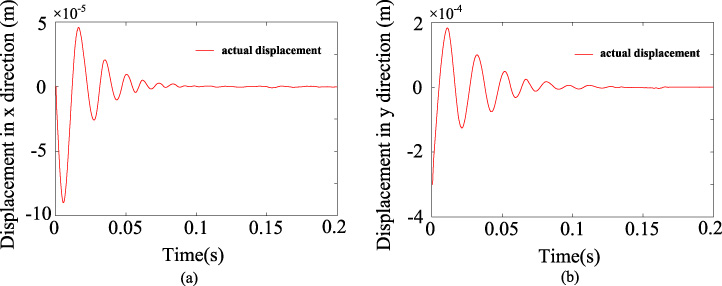
(a) Rotor radial displacement waveforms using the traditional suspension force control strategy in the x-direction. (b) Rotor radial displacement waveforms using the traditional suspension force control strategy in the y-direction.
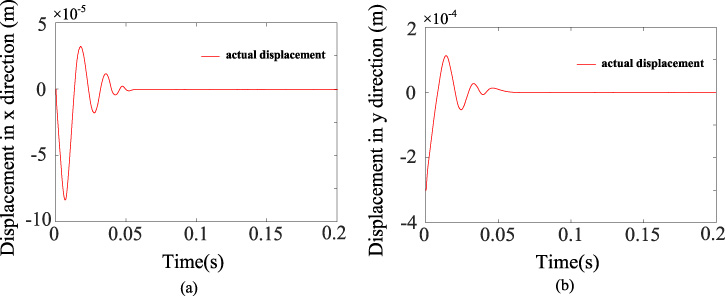
(a) Rotor radial displacement waveforms using the proposed suspension force control strategy in the x-direction. (b) Rotor radial displacement waveforms using the proposed suspension force control strategy in the y-direction.
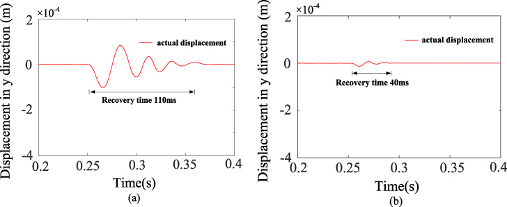
(a) Recovery waveform of the rotor radial displacement in the y-direction using the traditional suspension force control strategy with a sudden suspension force load in the shaft (b) recovery waveform of the rotor radial displacement in the y-direction using the proposed suspension force control strategy with a sudden suspension force load in the shaft.
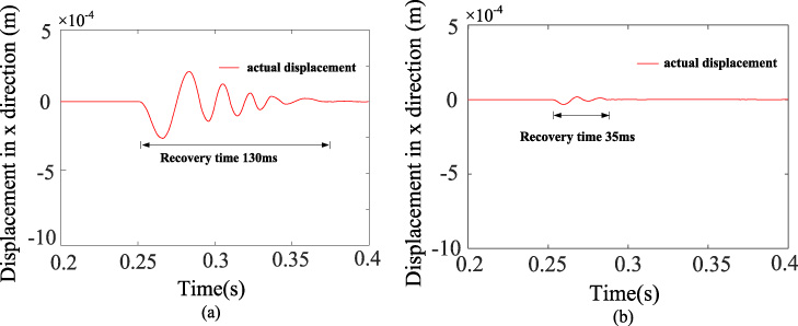
(a) Recovery waveform of the rotor radial displacement in the x-direction using the traditional suspension force control strategy with a sudden suspension force load in the shaft (b) recovery waveform of the rotor radial displacement in the x-direction using the proposed suspension force control strategy with a sudden suspension force load in the shaft.
Using the estimated rotor radial displacement results as the feedback of the traditional suspension force vector control, the curves of rotor radial displacement in the x and y direction are shown in Fig. 7(a) and (b). Compared with the estimated rotor radial displacement obtained by the displacement sensors of the vector control, the amplitude and time of the rotor radial displacement fluctuation has become larger and longer. To solve this problem, a method of directly controlling rotor eccentric displacement by using suspension force compensation is applied. Figure 8(a) and (b) show the curves of rotor radial displacement using the proposed suspension force control strategy in the x and y direction. We can see that the amplitude and time of the rotor radial displacement fluctuation are smaller and shorter.
Figure 9(a)(b) and Fig. 10(a)(b) show the recovery waveforms of the rotor radial displacement for a sudden suspension force load in the shaft. In Fig. 9(a) and Fig. 10(a), the estimated rotor radial displacement is used as feedback signal and the traditional vector control is used to achieve the stable operation of the suspension force system. The rotor radial displacement recovery waveforms are shown in Fig. 9(a) and Fig. 10(a). It can be seen that after applying a sudden suspension force to the shaft, the rotor requires 110 ms to return to the steady state in the y-direction and requires 130 ms to return to the steady state in the x-direction. While the proposed suspension force control strategy is applied, the recovery waveforms of the rotor radial displacement are shown in Fig. 9(b) and Fig. 10(b). As can be seen, the recovery time of the rotor radial displacement in the y-direction is to 40 ms and the recovery time of radial displacement in the x-direction is reduced to 35 ms. Therefore, the proposed suspension force control method can compensate for the effects of using the traditional suspension force control signal as feedback. The above simulation results show that the designed sensorless control system has good dynamic and static performance and the stable suspension of rotor can be achieved.
The detailed performance of the novel rotor radial displacement self-sensing method of the BIM based on the MRAS was reported in this paper. According to the Popov’ hyperstability, the stability of the proposed MRAS was verified. To make the amplitude and time of the rotor radial displacement fluctuations shorter and smaller, the direct control of rotor eccentric displacement with suspension force compensation was proposed. The simulation was carried out to verify the effectiveness of the proposed displacement self-sensing method and the suspension force control strategy. According to this method, the following advantages are as follow. Firstly, the estimated displacement is in accordance with the actual displacement exactly and the stable operation of the BIM can be also achieved. Secondly, this method is immune to the disturbance of suspension force load, and the estimated rotor radial displacement is determined by dq-axis components of currents of the torque windings, derivative of mutual inductance with respect to the rotor radial displacements and the self-inductance of the suspension force windings. Therefore, this method has a good robustness. Thirdly, the proposed MRAS-based suspension force compensation control method realizes the double closed-loop control of displacement and suspension force, which improve the static and dynamic performance of the displacement sensorless control system.
Footnotes
Acknowledgements
This work was supported by the National Natural Science Foundation of China under Projects 51875261, 51875255, U1664258, and U1762264, the Natural Science Foundation of Jiangsu Province of China under Projects BK20180046, BK20170071, and BK20180100, the “Qinglan project” of Jiangsu Province, the Key Project of Natural Science Foundation of Jiangsu Higher Education Institutions under Project 17KJA460005, the National Key Research and Development Program of China under Project 2017YFB0102603, the Six Categories Talent Peak of Jiangsu Province under Projects 2015-XNYQC-003, 2016-GDZB-096, and 2018-TD-GDZB-022, the Development of Strategic Emerging Industries of Jiangsu Province under Project 2016-1094, and the Postgraduate Research & Practice Innovation Program of Jiangsu Province under Project CXLX13_668.