
Abstract
The yokeless and segmented armature axial-flux in-wheel motor with amorphous magnet metal (AMM) stator segment has the advantage of low iron losses, but its open-slot structure causes high eddy-current losses of the permanent magnet (PM), which reduces the efficiency and reliability of the in-wheel motor. To avoid the demagnetization caused by the heat generated by PM losses, the mechanism of PM eddy-current losses reduction for the axial-flux in-wheel motor is revealed by the calculation model. In this paper, the time-step three-dimensional finite-element method (3-D FEM) is used to analyze the PM eddy-current loss caused by slotting effects, spatial harmonics, and time harmonics at different speeds. The effect of PM skewing, PM segmentation, and soft magnetic composite (SMC) layer inserted on the top of PM on eddy-current losses are compared. These methods cannot simultaneously meet the requirements of PM losses reduction and the electromagnetic performance of the motor. A novel combined stator segment with the SMC brim arranged on the top of the AMM stator teeth is proposed to improve the amplitude and distribution of the PM eddy-current density. The analysis results show that the combined stator segment can significantly reduce the PM eddy-current loss and improve the electromagnetic performance of the in-wheel motor.
Keywords
Introduction
Electric vehicles (EVs) driven by in-wheel motors feature a promising structure because of the convenience of energy conversion and reduction in mechanical losses [1]. The axial-flux permanent magnet (PM) (AFPM) in-wheel motors have many distinguished advantages such as high power/torque density, high efficiency, and compact axial length, and they are widely used in EVs [2–5]. The yokeless and segmented armature (YASA) topology is a new type of AFPM machines that comprises two external rotors and an inner stator [6]. The stator yoke of the YASA machine is removed and the stator segments connect by lightweight non-magnetic materials. Compared with other topological structure of AFPM machines, the YASA machine has the advantages of short end-windings, convenient assembly, light stator weight, low iron and copper losses, and high fault tolerance. It is one of the promising topological structure of AFPM machines in recent years.
Amorphous magnetic metal (AMM) is a new type of soft magnetic material with the advantages of high magnetic permeability and low hysteresis and eddy-current losses. Compared with the stator segment made of soft magnetic composite (SMC) or silicon steel, the YASA machine with the AMM stator segments has lower iron losses at high frequency [7,8]. Due to the hard and brittle properties of AMM, it is difficult to be machined. Moreover, the processed AMM is easy to reach the state of magnetic saturation and the loss density is increased [9]. Therefore, wound or stack AMM stator segments are used to reduce the influence of machining on iron losses, and the stator shoe is designed as an open-slot structure which has the advantage of being simple to manufacture [10–12]. However, PM eddy-current losses caused by the open-slot structure cannot be ignored [13].
The eddy-current loss of the in-wheel motor is caused by many factors. Due to the high conductivity, low Curie temperature, poor heat resistance, and high loss density of Nd-Fe-B, it is easier to generate eddy-current in a changing magnetic field, which leads to eddy-current losses. To exert the advantage of low iron losses of AMM material at high frequency, the YASA machine is usually designed with a large number of poles, and the PMs are used in a large amount. Besides, the YASA machine uses surface-mount PMs, so that the stator slotting permeance harmonics and magnetic motive force (MMF) harmonics caused by the discrete positions of stator winding conductors and time harmonics in the stator current directly act on the PMs, which makes the PMs easier to generate eddy-current losses [14–18]. Since the magnet-skewing technique is used to reduce the cogging torque and improve the electromagnetic performance of the in-wheel motor, it is necessary to calculate the amplitude and distribution of the eddy-current density according to PM shape, instead of simply calculating the average losses [19–21]. Finally, the MMF harmonics increase because of fractional-slot concentrated winding in the YASA machine, and the different pole-slot has a significant effect on PM losses. Although PM eddy-current losses account for a small proportion of the total losses of the in-wheel motor [22], they are easy to overheat the PM and decrease the residual magnetic flux density, thereby reducing the performance and even causing demagnetization of PMs, which adversely affect the reliable operation of the motor [23]. Therefore, it is necessary to study the PM eddy-current losses reduction method.
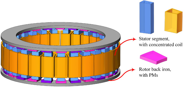
The structure of AMM-based YASA in-wheel motor.

Circumferential section and main sizes of the YASA.
Main parameters of the YASA
The calculation method of PM eddy-current losses includes the analytical method and the finite-element method (FEM). For radial flux permanent magnet (RFPM) machines, the air gap flux density is constant along the axial direction. While the flux direction of the YASA machine is parallel to the shaft, and the air gap flux density changes along the radial direction. Quasi three-dimensional (3-D) analytical method, two-dimensional (2-D) FEM, or 3-D numerical hybrid method cannot fully consider the factors of skin effects, variation of the flux density along the radial direction, end-effects, flux saturation, and PM shape [17,24–26]. Moreover, the modeling process for these methods is complicated. It is difficult to obtain the accurate amplitude and distribution of eddy-current losses by these methods for the YASA machine. The calculation of PM eddy-current losses in the YASA machine is a 3-D problem by its nature and the time step 3-D FEM is the most accurate method [27].

Schematic disposition of the coils (A, B, C, a, b, c) and the PMs.

Phase current waveforms and harmonic contents.

The calculation model of PM eddy-current losses.
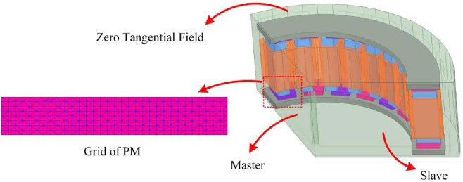
3-D FE model in Ansys Maxwell software.

Eddy-current density distribution of PMs.
The reduction of PM eddy-current losses is always a major concern in both AFPM and RFPM machine design. Hemeida, Sergeant and Vansompel [17] studied the influence of the stator slot width on PM eddy-current losses. The eddy-current density at the corresponding position of the stator slot is the largest. Decreasing slot width can reduce eddy-current losses effectively, but stator losses will increase. Donato, Capponi and Caricchi [28,29] studied the effect of SMC wedge on PM eddy-current losses. The wedge can significantly reduce PM eddy-current losses. As the wedge height increases, the eddy-current loss reduction is not obvious, and the wedge losses increase slightly. As the wedge width increases, the eddy-current loss decrease, the wedge losses increase, and the sum of the two remain unchanged. Sergeant, Vansompel, Hemeida, Bossche and Dupre [30] studied the effect of direction and number of segments on the T-shaped PM eddy-current losses. With the increase of segment numbers, the losses decrease significantly. However, as the frequency of inverter power supply increases, the suppression effect of the segment on eddy-current losses is weakened. Jara, Lindh, Tapia, Petrov, Repo and Pyrhonen [31] proposed a steel lamination inserted on the top of PMs to reduce eddy-current losses. In this paper, the effect of the steel lamination height and the number of PM segments on eddy-current losses are studied. As the steel lamination height increases, the eddy-current loss increase first and then decrease, and the eddy-current loss of the steel lamination are negligible. Jie and Zhu [32] studied the effect of the height, width, and position of auxiliary slots on rotor eddy-current losses. The eddy-current loss is increased due to the enhanced asynchronous harmonics in the magnet field caused by the auxiliary slots.
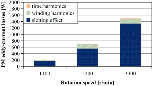
Separation of eddy-current losses of PM at different speeds.
Rotor with different skewed PMs.
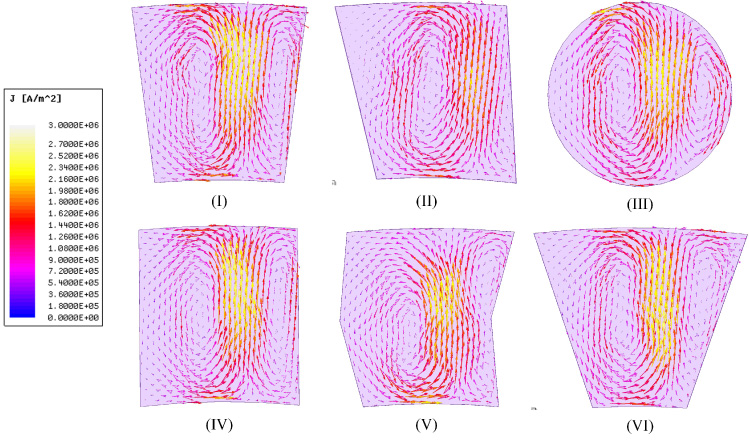
Eddy-current density loops with different skewed PMs.

Comparison of eddy-current losses per unit area of different skewed PMs.
This paper is organized as follows. The description of the YASA in-wheel motor with AMM stator segments is presented in Section 2, where the calculation of PM eddy-current losses by 3-D FEM is explained in detail. Section 3 presents the effects of PM skewing, PM segmentation, and SMC layer inserted on the top of PM on eddy-current losses and electromagnetic performance of the motor. A novel combined stator segment using AMM and SMC is proposed to reduce the PM losses. The conclusions are summarized in Section 4.
The structure of a conventional AMM-based YASA in-wheel motor is shown in Fig. 1. The stator segment is wound by AMM strip and has a hollow fan shape in cross-section. Open-slot structure is used to avoid the influence of machining on the electromagnetic performance of the stator segment. Fractional slot concentrated windings reduce considerably the manufacturing and assembly costs due to their shorter end windings and pre-wound coils. The PM is made of Nd-Fe-B N38EH, which is fan-shaped and has a conductivity of 160 × 10−8 Ω ⋅ m. The PM is fixed by the rotor back iron and the rotor support to prevent it from moving at high speed. The rotor support is made of glass fiber which is electrically non-conductive and non-ferromagnetic. It has no effects on rotor eddy-current losses, which can be ignored in modeling.
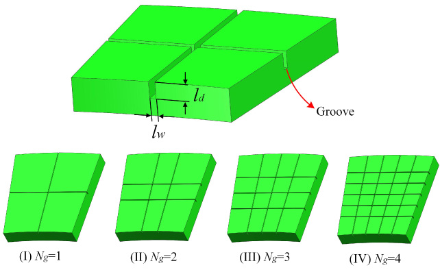
PM segmentation with different groove groups.

Eddy-current density distribution of PMs.

Eddy-current losses with different (a) groove groups and (b) width of the groove.

Comparison of torque with and without PM segmentation.
Figure 2 shows the circumferential section and depicts the main geometrical variables. The main parameters of the YASA machine are shown in Table 1.
The PM eddy-current losses are caused by three main sources: (1) Permeance variation caused by stator slotting, (2) Winding harmonics, and (3) Time harmonics. Flux density harmonics are caused by these three sources, which are not synchronous with the rotor rotation speed. 3-D FEM (ANSYS MAXWELL) and loss separation technique are used to study the influence of three sources. The PM eddy-current losses caused by the slotting effects can be obtained under no-load conditions. The PM eddy-current loss caused by the winding harmonics is related to the winding distribution, which is the loss difference between a pure sinusoidal current supply and no-load condition. The details of the winding distribution and the PMs are shown in Fig. 3. The upper and lower case letters depict that the coil is wound clockwise and counterclockwise, respectively. The YASA machine is fed by a current-controlled voltage source inverter (VSI) and the variable voltage source is obtained by pulse-width modulation (PWM). The time harmonics present in the output voltage of the VSI, which is affected by the switching frequency of the VSI and the modulation ratio [30]. The phase current waveforms for the VSI PWM fed motor corresponding to a carrier frequency of 10 kHz and their harmonic contents are provided in Fig. 4. The PM eddy-current losses caused by time harmonics can be obtained by subtracting the PM losses caused by slotting effects and wingding harmonics from the PM losses caused by PWM.
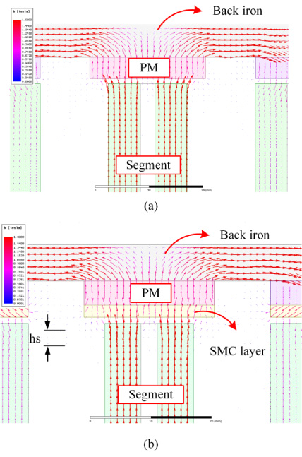
2-D flux density vectors with and without SMC layers.

Eddy-current density distribution of PMs.

PM eddy-current losses with the thickness of the SMC layer.

Comparisons of (a) torque, (b) harmonic contents, and (c) THD for prototype motor with different thicknesses of SMC layers.
The calculation model of PM eddy-current losses given in [21] is shown in Fig. 5. The model assumes that the shape of the PM is a rectangle of length l
PM and width w
PM. In any loop of the PM, the width in the x-direction is dx, and the width in the y-direction is dy. The eddy-current density
It can be seen from (1) that the magnitude and distribution of the PM eddy-current density are related to the PM shape, the position on the PM, the permeance variation on the PM, and the PM electrical resistivity. The PM eddy-current loss can be expressed by [22]:
The 3-D FEM for accurate eddy-current losses calculation is time-consuming and computationally intensive. To reduce the calculation time, the model is simplified and the unit motor (1/3 model, 9-slots/8-poles) is used for the calculation. The FE model and boundary conditions are shown in Fig. 6. The PM mesh needs to be encrypted. The calculation time is two electrical cycles to ensure that the output value of the eddy-current loss is stable.
Figure 7 shows the distribution of the eddy-current density and its loops of a PM at a certain time. Eddy-current density loops are irregular annular closed curves, and the denser the eddy-current density line, the greater the eddy-current loss. The eddy-current density is the largest at the corresponding position of the stator slot, and the smallest at the four corners. As the skin depth increases, the eddy-current density decreases. When the rotational speeds are 1100 r/min, 2200 r/min, and 3300 r/min, respectively, the average eddy-current losses caused by the three sources are shown in Fig. 8. The eddy-current loss caused by the slotting effect at different speeds is the largest, accounting for more than 80% of the PM eddy-current losses, which is much larger than the losses caused by MMF harmonics. At rated speed (1100 r/min), the output power is 3.3 kW, and the PM eddy-current losses account for 6% of the output power of the motor. The eddy-current loss caused by the slotting effect account for 5.3% of the output power, which is one of the main causes of motor losses.
To compare the reduction effects of different stator and rotor structures on PM losses of AMM-based YASA, the winding distribution and VSI parameters are not considered in this paper. According to (1), increasing the length of the air gap will reduce the PM eddy-current loss, but will also reduce the flux density and the average torque. This paper sets the air gap length to 1 mm.
Effect of PM skewing
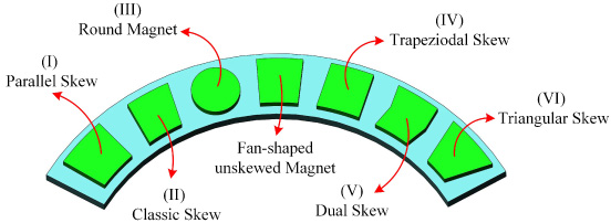
The fan-shaped unskewed PM has the advantages of simple design and convenient manufacture and is often used as the magnetic pole of the YASA machine. However, the fan-shaped PM produces a larger cogging torque. PM skewing method can help reduce high-order back electromotive force (EMF) harmonics and cogging torque [19]. The commonly used skewed PMs are shown in Fig. 9.
The pole-arc ratio is given by
In this paper, the eddy-current loss of different skewed PMs is obtained when the pole-arc ratio is 0.7. Due to the areas of different PM shapes that cannot be completely equal, the results can be expressed by the eddy-current loss per unit PM area [33]. Figure 10 shows the eddy-current density loops with six kinds of skewed PMs. Their distribution is slightly different from that of the fan-shaped unskewed magnet. However, the eddy-current density at the corresponding position of the stator slot is still the largest. As shown in Fig. 11, the loss reduction effect of the round magnet is better. This is because the area and the flux density of the round magnet are the smallest, and the influence of the flux density on the eddy-current loss is more significant.
PM segmentation is a well-known method to reduce PM eddy-current losses for both AFPM and RFPM. This method can more easily be applied to AFPM machines than RFPM machines, owing to their planer air gap and flat magnet surface area. The wire cutting technology is used to cut the groove with the width l
w
on the PM, and the large eddy-current loop on the PM is cut into several small eddy-current loops. This technology can shorten the eddy-current loops and the PM eddy-current losses can be reduced effectively. According to the distribution of the eddy-current density in Fig. 7, the groove should be located where the eddy-current density is high, and the effect of cutting loop is the best. The depth of the groove is mainly determined by the skin depth of the high-order harmonics. If the depth of the groove is too shallow, the purpose of reducing the eddy-current loss cannot be achieved. If the depth of the groove is too deep, the manufacturing cost is increased. It is reasonable that the depth of the groove is equal to the skin depth of the high-order harmonics. The skip depth can be calculated by [34]:
where f r, v is the induced rotor frequency of the vth space harmonic, u r, PM is the relative permeability of PM, u 0 is the vacuum permeability.
The electric frequency of the motor is 220 Hz. The skin depth obtained by (4) is 40.4 mm. This value is higher than the PM thickness (4 mm). Therefore, the depth of the groove is equal to the PM thickness.
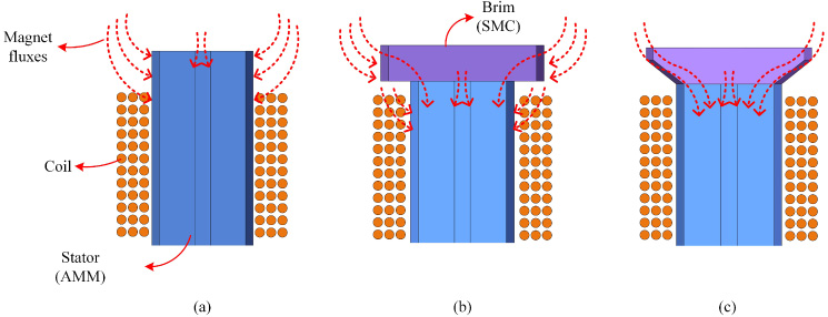
Stator segment of (a) open-slot structure, (b) semi-closed slot structure I and (c) semi-closed slot structure II.

The structure of the YASA in-wheel motor with combined stator segments.
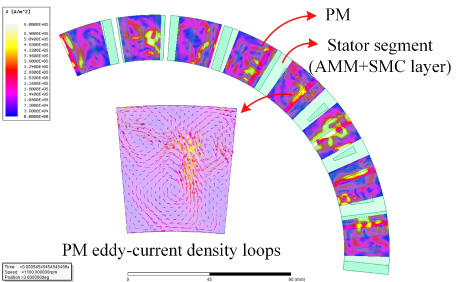
Eddy-current density distribution of PMs.
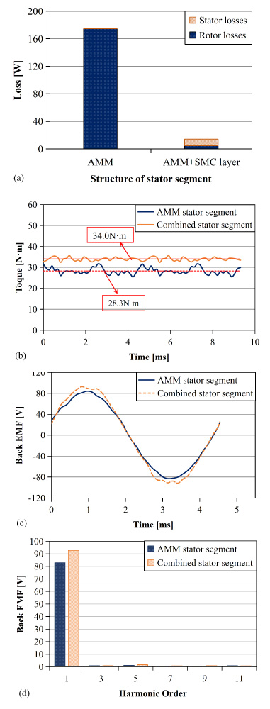
Comparison of (a) losses, (b) torque, (c) back-EMF, and (d) back-EMF harmonic order with AMM and combined stator segment.
On the premise of meeting the requirement of loss reduction, the width of the groove should be as small as possible. The grooves on the PMs increase the air gap reluctance of the motor, reduce the flux density of the air gap, and generate new harmonics. The eddy-current loss is calculated when the width of the groove is 0.2 mm, 0.4 mm, 0.6 mm, and 0.8 mm, respectively. The number and direction of grooves have effects on the reduction of eddy-current losses, and the losses decrease most when the PM is grooved both radially and axially [35]. As shown in Fig. 12, a radial groove and an axial groove are called a group of grooves, which divides the PM into four segments. The eddy-current loss is calculated when the grouping number N g is from 1 to 4.
As can be seen from Fig. 13, the direction of the eddy-current density loops is changed by the grooves, which block the eddy-current density loops, increase the resistance of the eddy-current and make the eddy-current density distribution more uniform, thereby reducing the eddy-current loss. Figure 14(a) shows that when the width of the groove l w is 0.2 mm, the eddy-current loss decreases as the number of groove groups increases. Figure 14(b) shows that when the number of groove groups is 2, the eddy-current loss decrease as the width of the groove increases. This is because the air gap reluctance increases as the number of groups and the groove width increase. However, the effect of PM segmentation on the reduction of eddy-current losses is not significant. While reducing the PM eddy-current loss, the electromagnetic performance of the motor should be fully considered, such as the total harmonic distortion (THD) of the back-EMF, torque ripple, and total losses of the motor. The torque of the PM segmented motor (the width of the groove is 0.2 mm, the number of groove groups is 2) and the unsegmented motor is shown in Fig. 15, respectively. It can be seen that the torque ripple of the PM segmented motor is increased by 1.6 times, which makes the motor unable to meet the requirements of vibration and reliability.
Installing the magnetic conductive layer on the air gap side of the PM is one of the effective methods to reduce PM losses caused by the slotting effect. The variation of the flux density in the PM can be reduced by using a magnetic conductive layer of SMC or grain-oriented silicon steel lamination. The SMC layer is used for simulation in this paper. The 2-D flux density vectors with and without the SMC are shown in Fig. 16. The flux induces the eddy-current inside the SMC, which smooth the magnetic field in the PM. The SMC helps redistribute eddy-current losses of the rotor, reducing the eddy-current density in the PM. Figure 17 shows that adding the SMC on the top of the PM has a significant effect on eddy-current density loops. The maximum eddy-current density is at the boundary of the PM, and the minimum is at the center, which is independent of the position of the stator slots. The relationship between the total loss (losses in PMs and SMC layers) and the thickness of the SMC is depicted in Fig. 18. With the increase in the thickness of the SMC, the PM loss decreases significantly, the SMC loss increases slightly, and the total loss decrease. When the thickness of the SMC is 2 mm, the PM loss is reduced to 5% of the loss when the SMC is not added. If the thickness is further increased, eddy-current losses are not significantly reduced, but the axial length and weight of the motor will increase. Figure 19(a) and (b) show that as the thickness of the SMC increases, both the torque and the induced voltage increase as the SMC thickness increases from 0 mm to 2 mm, after which they decrease. Figure 19(c) shows that the total harmonic distortion (THD) of the back-EMF is significantly increased, mainly due to the increase of the third harmonic.
Effect of combined stator segment
Due to the modification in the rotor is difficult to significantly reduce the PM eddy-current loss, and the electromagnetic performance of the motor will deteriorate. Therefore, it is a feasible method to reduce the PM eddy-current loss by modifying the stator. However, the conventional AMM-based motor adopts an open-slot structure and the eddy-current loss increases as the slot width increases [36]. Installing the magnetic wedge on the stator shoe can reduce the stator slot width, but the machining process will degrade the electromagnetic performance of the AMM. Moreover, the axial electromagnetic force acting on the wedge will cause stress concentration in the AMM and reduce the reliability of the stator segment.
This paper presents a combined stator segment, the design process of which is shown in Fig. 20. Due to the week permeability of the conventional AMM stator shoe, the air gap reluctance is large. To avoid the magnetic fluxes penetrating the coils directly, the stator segment protrudes from the upper surface of the winding area by 8 mm, as shown in Fig. 20(a). The 6-mm protrusions are removed from the AMM stator segment, and a 6-mm SMC brim is added to the top to absorb the flux, as shown in Fig. 20(b) (semi-closed slot structure II). The length of the stator segment is still 64 mm. The utilization of the flux is more effective due to the larger surface obtained by the SMC brim. To reduce the air gap reluctance between the SMC brim and the AMM stator segment, and then reduce the high-order harmonics of back-EMF, the structure of the SMC brim changed, as shown in Fig. 20(c) (semi-closed structure III). Since the stator segment uses pre-wound coils, the limitation of the coil diameter to the slot width can be ignored when designing the SMC brim. However, the effect of the slot width on the flux leakage between the SMC edges should be considered, and the minimum sum of iron losses and PM losses should be taken as the design objective.
Figure 21 depicts the novel YASA in-wheel motor with combined stator segments. AMM stator segments and SMC edges are glued together and fixed by epoxy resin after winding. Figure 22 shows that the amplitude of the PM eddy-current density decreases obviously by using combined stator segments. The highest eddy-current density is still located at the corresponding position of stator slot, but the area of the high eddy-current density region decreases with the decreases of the slot width. Figure 23(a) shows that the PM eddy-current loss is reduced from 174.4 W to 4.7 W. The stator loss is slightly increased, and the total loss is reduced by 73%. The weight of the stator increased by 0.864 kg. The electromagnetic performance of the motor is significantly improved, the average output torque is 34 N ⋅ m, which is increased by 20%, and the torque ripple is reduced by 6%, as shown in Fig. 23(b). The induced voltage is 92.6 V, which is increased by 12%, and the high-order harmonics are unchanged, as shown in Fig. 23(c) and (d).
Conclusions
To reduce the PM eddy-current loss of the axial-flux in-wheel motor with AMM stator segments, a 3.3 kW, 24-pole 27-slot YASA machine is studied in this paper. The traditional methods for improving the eddy-current loss, such as PM skewing, PM segmentation, and SMC layer on PM are analyzed and compared by 3-D FEM. These methods cannot reduce the eddy-current loss as expected and will deteriorate the electromagnetic performance of the motor. Therefore, the AMM stator segment is improved, and a combined stator segment with SMC brim is proposed, which can significantly reduce the PM eddy-current loss and the total loss of the in-wheel motor.
Footnotes
Acknowledgements
This research did not receive any specific grant from funding agencies in the public, commercial, or not-for-profit sectors.