
Abstract
This paper deals with the development of a simplified numerical model with the aim of assessing the impact of using grain-oriented electrical steel (GOES) in switched reluctance machine (SRM) on its performance. Different grades of steel are studied to firstly analyze their impact on the inductance and the electromagnetic torque change. Then, both the simplified model and the steel grades helped determine the level of contribution of anisotropy and high permeability individually. In this paper, the impact on electromagnetic torque is evaluated along with a local analyses of the flux lines distribution and the numerical model allows to draw conclusions on the device performance when anisotropy is introduced. Although the GOES numerical model used for finite elements simulations is not a fully developed model, it is accurate enough for our study. The originality of this paper lies in the fact that the developed model is relatively simple and accurate enough to investigate all the electromagnetic phenomena and draw conclusions which can be applicable to a more complex and time-consuming electromagnetic device. The second original aspect is the introduction of GOES in an axial flux SRM (AFSRM).
Keywords
Introduction
When designing rotating electrical machines with large power-to-weight ratio and high efficiency, it is advantageous to introduce high performance materials, while taking into account environmental and financial costs. In this context, SRM [1] are suitable candidates giving the fact they are magnet free and have no winding at the rotor [2]. They are known to be robust and reliable [3] even if they operate in harsh environments. They can also function at high torque or high speed. In addition to these advantages, several studies on the AFSRM have shown that the latter is more compact compared to a radial flux SRM (RFSRM) [4,5], allowing the introduction of these machines to electric vehicle applications.
Grain oriented electrical steel (GOES) offer excellent performance regarding iron losses and permeability. However, these performance vary depending on the magnetization direction because of the steel anisotropic nature. Therefore, there are several difficulties to use this material in electrical rotating machines, except with segmented magnetic circuits. Hence, it is necessary to find appropriate machine structures allowing the best use of the GOES inherent qualities. It is even more difficult, since GOES has very high permeabilities. As a matter of fact, this kind of electrical steel has limited iron losses, higher levels of permeability and higher saturation levels compared to conventional non-oriented grain electrical steel.
Despite the difficulties to integrate GOES in a rotating system, previous works have been focused on their use in classical alternative machine. As a result [6], use GOES in the magnetic circuit of induction machines. They showed that their efficiency can be improved by shifting each lamination without segmentation by an angle of 90o which was experimentally determined. That way, the flux flows through laminations, passing from a lamination to an adjacent one in order to benefit from the easiest magnetisation direction.
However, the most suitable machines for GOES use seem to be SRM. Some authors studied the performances of axial and radial flux SRM and showed that with GO steel, the electromagnetic torque can be improved by up to 21% compared to a conventional SRM. The authors of [7] introduced segmented grain-oriented steel in c-core stator teeth of an axial flux SRM to deal with issues of low inductance ratio. This has showed a 5% improvement in the inductance ration. Madhavan in [8] used GOES in both stator and rotor teeth in a dual stator and central rotor AFSRM. The rotor and stator using GOES are connected to a retaining disk and the stator yoke by bolts. After analyzing different shapes and deviation angles between the magnetic flux and rolling direction of the GOES, the maximum electromagnetic torque of the proposed design showed a 21.4% increase in comparison with the one of a conventional non-oriented electrical steel. Then, Sugawara and akatsu in [9] introduced GOES in both stator and rotor teeth of a RFSRM showing an increase of the average torque by 10% in comparison with NO steel. As far as the numerical modeling is concerned, dealing with both anisotropy and saturation in 3D magnetic circuit modeling is still complex and time-consumming, especially for convergence difficulties.
In this paper, an AFSRM structure integrating GOES in the rotor is presented. Then, in order to avoid a heavy and time-consuming 3D simulation, a simple numerical model is used to evaluate the GOES local impact by analyzing the flux lines distribution. A detailed comparison featuring different configurations and their corresponding inductance and torque profiles is given.
AFSRM and numerical model presentation
AFSR magnetic circuit
In this study, the double salient SRM considered is an axial flux machine, with a rotor positioned between two outer stators as shown in Fig. 1.

Flux path (transverse loop).
Such structure allows two different flux paths [10]: either a loop through the rotor yoke or simply cutting across the rotor (Fig. 1). The second flux path configuration is considered in our study since it enables the GOES use defined by three directions: the Rolling (RD), Transverse (TD) and Normal direction (ND). The first two directions are within the same plane and the third one is normal to the plane. The main idea is to take advantage of the performances in the RD when the flux cuts across the rotor as shown in Fig. 1. This way, steel sheets can be arranged in two configurations as shown in Fig. 2, giving two planes as options for the flux path: in the transverse direction (TD) and rolling direction (RD) or the normal direction (ND) and RD which may change the saliency effect.

GOES configurations in the AFSRM.
In order to evaluate the anisotropy contribution and what the GOES performance brings in a rotating machine without modeling a time consuming and complex 3D geometry, the authors propose a simplified model shown in Fig. 3. It makes it possible to take into account saliency and rotation. The aim is to describe and analyze through this model the phenomena occurring around the 3D machine teeth.

Simplified numerical model.
The model is made of a black stator yoke with a very high permeability in comparison with the rest of the magnetic circuit. This is to ensure that the magnetic state of the stator yoke does not influence the rest of the studied circuit. In addition to the yoke, two stator teeth and a straight rotor were modeled in green. In the model, θ is the angle representing the rotor position between alignment and the opposition position. Anisotropy is introduced using a diagonal tensor with a normal permeability which value is defined in [11], first on the stator to simplify the anisotropy modeling when the rotor position is changed. Then, the numerical model also permits the use of GOES at the rotor to analyze the flux lines distribution when anisotropy is introduced in the rotating parts.
Three different types of electrical steel are considered:
M400: Isotropic non-oriented grain electrical steel of 0.5 mm; HGO35: Anisotropic high-grade GOES of 0.35 mm, which can be arranged in the two different configurations shown in Fig. 2; Iso: Isotropic high-grade non-existent steel with a B(H) characteristic identical to the HGO35 rolling direction properties.
The third isotropic steel referred to as ‘Iso’ is actually a non-existent material but the inductance and torque results compared to those obtained with the two other cases will make it possible to separate the influence of the anisotropy from the steel quality and permeability.
In order to highlight the contribution of both the steel quality (involving permeability and flux density saturation level) and the anisotropic nature of the material, multiple configurations were simulated. While the rotor (Fig. 3) was characterized with M400 steel in the first comparison, stator teeth used M400, HGO35 GO steel or isotropic steel with a B(H) characteristic identical to the HGO35 rolling direction properties. Another series of configurations where the stator teeth are characterized with M400 steel and the rotor uses different steel types: M400 steel, HGO35 and high grade isotropic steel presented earlier. A description of all the studied and simulated configurations is given in Table 1.
The designation HGOTD35 refers to HGO35 steel arranged following the first configuration in Fig. 2 and HGOND35 refers to the second one. In the rest of the document, all the studied cases will be named according to this designation template ‘Stator steel type - Rotor steel type’.
A summary of the studied configurations
With the anisotropic nature of GOES, difficulties can be experienced when modeling a rotating structure due to the rotating field and the alterations in the flux path. However, there are several advantages to the use of GOES such as an excellent permeability, high saturation and flux density and low losses [12]. Also, the introduction of very thin GOES sheets minimizing eddy losses which engaged more research towards the integration of GOES in rotating machines. For thinner laminations such as (0.27 mm), core losses can be as low as 0.8 W/Kg at 1.5 T and 50 Hz [13]. Because GOES behavior can be influenced by a couple of factors such as the grain size and stress, accurate modeling of magnetic hysteresis for GOES can become a tricky task. Furthermore, GOES exhibits strong non linearity and anisotropy making it difficult to deal with in rotating devices. It gets particularly difficult to reproduce with accuracy the magnetic hysteresis in the region before the knee and to predict magnetic losses [14,15]. With these difficulties, no thorough modeling which takes into account the full behavior of GOES has been addressed to date.
The FE simulation is performed using the code GETDP and the anisotropic nature of the GO electrical steel is defined by three directions: RD, TD and Normal direction ND (Fig. 4).

B(H) curves in the numerical model.
The relation between the magnetic flux density and the magnetic field can be expressed using a tensor as follows:
Inductance comparison
The inductance simulation results given in this section were computed for a current of 0.8 A (Fig. 5 and Fig. 6). In the model, the inductors are defined with 1000 turns in series per phase. The inductance results cover a rotor position range from 0 to 25 degrees, which represents the interest area for torque production between the alignment position and the flat section representative of the opposition. In Fig. 5, three inductance curves are displayed for the first three cases defined in Table 1 at the same input current of 0.8 A. The aim of Fig. 6 is to understand and separate the contribution of both the anisotropy introduced by the HGO35 steel and high permeability only given by Iso steel.

Influence of anisotropy on the inductance.
Figure 5 shows that the curves corresponding to the use of anistropic and isotropic non-existent materials (HGO35 TD-M400 and Iso-M400) are overlapping, suggesting that the anisotropic nature does not play a role in improving the inductance value. This confirms that the anisotropic nature of the material has no effect on the inductance performance, but only the high permeability and quality of the steel can affect it. As a result, a steeper slope is observed compared to the case using the M400 steel.
These results show that using a higher quality steel improves the maximum inductance value when GOES is introduced at the stator teeth. Since it has been showed in Fig. 5 that the use of HGO35 and the non-existent steel resulted in identical curves concluding that only high grade material influences the inductance shape, cases using the non-existent material referred to as ‘Iso’ will not be presented in Fig. 6.
In Fig. 6, the results show that using a higher quality steel improves the maximum inductance value by 5.9% when GOES is introduced at the stator teeth, by 2.1% when GOES is at the rotor and by nearly 12% when GOES is used in both.
In general, it can be observed that the highest inductances peaks and the steepest slopes are attributed to the cases where anisotropy is used in both the stator teeth and the rotor (HGOTD35-HGOTD35, HGOTD35-HGOND35 and HGOND35-HGOND35).

Inductance variations with rotor position at 0.8 A.
The configurations HGOTD35-HGOND35 and HGO35ND–HGO35ND show relatively similar waveforms. Both inductances have steeper slopes on the first half of the variation, starting from the alignment position (Fig. 7). After a knee point, the slopes become smoother in the second half of the inductance curves. The impact of these changes on the static torque are discussed further.

Inductance for 3 anisotropic cases at 0.8 A.
For a better understanding of the anisotropy behavior, it is worth considering a local investigation by analyzing the flux distribution between the rotor and a stator tooth. Therefore, a distribution of the flux lines is shown in Fig. 8 in a layout where the rotor is rotated by 12.5 degrees and both stator and rotor are using M400 steel.

Flux lines distribution for M400-M400.
In Fig. 9, GOES is introduced at the stator teeth (HGOTD35-M400) and shows a straighter path of flux lines due to anisotropy which is the sole element influencing the flux path. The same behavior is observed when anisotropy is introduced in the rotor (Fig. 10). When anisotropy is introduced in the stator (Fig. 9), it can be noticed that the highest induction level is located horizontally in the tooth upper section whereas in Fig. 10 it is located vertically along the stator tooth tip.

Flux lines distribution for HGO35 TD-M400.

Flux lines distribution for M400-HGO35 TD.
In Figs. 11 and 12, GOES is used in both stator teeth and the rotor (HGOTD35-HGOTD35 and HGOND35-HGOND35). By analyzing the flux distribution of the two last cases (HGOTD35 -HGOTD35 and HGOND35-HGOND35), it can be noted that in the case HGOTD35-HGOTD35 flux lines tend to generally follow their path through iron in the rotor before crossing to the stator tooth. However, for HGOND35-HGOND35 there are fewer flux lines following the iron path and are rather looping around.

Flux lines distribution for HGO35 TD-HGO35 TD.
Flux lines distribution for HGO35 ND-HGO35 ND.
Similarly to the inductance, the electromagnetic static torque profile is shown (Fig. 13) for the same current level (0.8 A).

Influence of anisotropy on the electromagnetic torque.
In Fig. 13, three torque curves are shown for three cases aiming to separate the influence of anisotropy from high permeability. The results in Fig. 13 are in line with the inductance results (Fig. 5) as it can be concluded that the anisotropic nature does not influence the electromagnetic torque waveform. For the rest of the analysis only M400 steel and anisotropic HGO35 steel will be taken into account.
The most important improvement in the electromagnetic torque mean value (Fig. 14) is attributed to the cases with HGO35 in both the stator teeth and the rotor. They show an increase higher than (14%) of the torque mean value in comparison with the M400–M400 case. Then, an increase of (6.8%) is noticed when GOES is introduced in the stator versus (2.6%) increase only when GOES is in the rotor. The introduction of HGO35 steel arranged according to the second configuration (Fig. 2) shows an obvious change in the torque waveform (Fig. 15). This is mainly due to the change in the inductance waveform.

Torque variations with rotor position at 0.8 A.
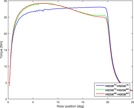
Torque for 3 anisotropic cases at 0.8 A.
The plateau noticed for HGOTD35 -HGOTD35 is maintained across a longer rotor position range values in comparison with the two other cases. HGOTD35-HGOND35 and HGOND35-HGOND35 results show almost superposed waveforms. Indeed, a small difference in the static torque shape is spotted. In the HGOND35-HGOND35 configuration, the static torque shows a sharper rise than the TD configuration and a higher maximum torque value. This torque then drops to a lower value in accordance to the inductance variation discussed in Fig. 7. However, it is observed that despite the change in the electromagnetic torque aspect the three waveforms have the same torque mean value.
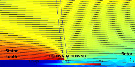
For a better understanding of the torque behaviour, an analysis at two key rotor positions was done: at 6° where the configuration HGOND35-HGOND35 has a higher instantaneous static torque value than HGOTD35-HGOTD35 and at 19° where HGOND35-HGOND35 shows a lower static torque value.
∙ At the rotor position: 6°

Both configurations flux lines distributions at 6°.
In the case HGOTD35-HGOTD35 the steel sheet configuration is defined with the RD in the x axis and TD following the y axis, whereas HGOND35-HGOND35 has the RD according to the x axis and the ND following the y axis. This explains the flux paths followed in both cases in Fig. 16.
In Fig. 16a, the flux lines crossing from the rotor to the stator teeth tend to slightly follow a vertical path according to the TD before quickly aligning with the easy magnetization direction (RD). For the second case (Fig. 16b), the flux lines follow more easily the RD direction as the ND has less effect on the flux lines deviation. With a flux lines distribution focused mainly on the rotor and stator teeth ovelapping region, the induction distribution for the ND case will influence the flux density and, consequentially, give a higher inductance resulting in a static torque increase.
∙ At the rotor position: 19°
This is the part where the case defined by the RD and ND (Fig. 17b) torque value drops in comparison with the case defined by RD and TD (Fig. 17a).

Both configurations flux lines distributions at 19°.
A shift in the saliency effect happens starting from the position where the rotor is halfway overlapping with the stator teeth. When approximating the position where rotor and stator are no longer facing one another, the ND case (Fig. 17b) becomes noticeably more anisotropic which reverses the saliency effect causing a drop in the static torque value.
Table 2 summarizes the results for all the steel configurations studied. It shows the contribution of these configurations in the inductance slope change and the electromagnetic torque mean value.
The percentage increase given below are always calculated compared to the reference case: M400-M400.
Results analysis summary at 0.8 A.
This simplified numerical model has allowed to analyze all the phenomena needed to understand the behaviour of such device when anisotropy is introduced. The introduction of an isotropic nonexistent material enabled to separate the anisotropy contribution from the steel high permeability. This has showed that only high permeability and quality steel have an influence on the inductance form. Flux lines distribution, inductance and electromagnetic torque waveforms were also analyzed. Although, this analyses showed that the best improvement in the torque’s mean value happens when GOES is introduced in both the stator teeth and the rotor, the feasibility of this configuration needs to be later assessed for a full 3D AFSRM. It is interesting to note that this investigation work has also showed that using GOES at the stator teeth only or the rotor only also gives a satisfying improvement in the torque value. Based on these results, future work will include a reasoning on the feasibility of these configurations in the studied machine.
Footnotes
Acknowledgements
This work has been achieved within the framework of CE2I project (Convertisseur d’Energie Intégré Intelligent). CE2I is co-financed by European Union with the financial support of European Regional Development Fund (ERDF), French State and the French Region of Hauts-de-France .