
Abstract
This paper investigates the braking force characteristic of permanent magnet eddy current brake with high acceleration. Compared with the braking force characteristics under quasi-static condition, the braking force considering the effect of high acceleration lags behind the quasi-static braking force before and after the critical speed. Meanwhile, there is a transition phase near the critical speed, and the peak value of the braking force is higher than that in the quasi-static approximation. The calculation of braking force under quasi-static condition is derived by solving the boundary value problem. The accuracy of the analytical model and the finite element model is verified through comparing the results of both models. The influence factors on the braking force characteristics are further analyzed. The results show that the increasing of the conductivity, thickness of conductor plate and the length of the permanent magnets can increase the effect of acceleration. The effect of acceleration has little relation with the permanent magnet height and the air gap length.
Introduction
Eddy current brakes are employed in many industrial applications, such as high speed train braking systems, automobile suspension and auxiliary braking devices due to the advantages of no mechanical contact, high reliability and simple structure [1–4]. In order to design eddy current brakes that meet the requirements of use, it is necessary to master their braking force characteristics.
The problem of electromagnetic field computation can be solved by using analytic method and finite element method (FEM) [5–7]. The analytical models provide straightforward physical relationships between the braking force characteristics and parameters. However, it is generally difficult to derive analytic expressions, and the application is strictly limited. FEM is suitable for eddy current brakes of various structures, but can be very time consuming depending on the size of the finite element model. Bae et al. calculated the eddy current damping force as the result of a magnet in a copper applying the Biot-Savart law, but without taking the back reaction of the induce eddy current into account, so the analytical model is not accurate at high excitation frequencies [8]. Jang et al. derived two-dimensional (2-D) analytical field solutions using the Fourier series method, and present comparisons between analytical results and experimental data [9]. Shin et al. predicted the braking torque and normal force on the basis of an analytical field computation using a space harmonic method and confirm the validity of the analysis by finite element analysis [10]. An analytical model of the hybrid excitation linear eddy current brake is built based on the magnetic circuit method and the layer theory approach in [11]. Then the finite element analysis is employed to confirm the accuracy of the analysis. The magnetic field solutions are obtained by considering three-dimensional (3-D) case using a simple and effective axial dependence modeling in [12]. And the analytical magnetic calculations is verified through FEM. All these studies involve only quasi-statics. Namely, a time-dependent secondary magnetic field generated by the change of primary induced eddy currents is neglected [13]. This makes it accurate in case of small acceleration, but will cause errors at high accelerations.
In this paper, the expression of braking force is derived based on a 2-D analytic model neglecting end effects under quasi-statics. The braking force obtained by analytic method and FEM are compared to validate the analytical model and finite element model. Then the braking force characteristics of eddy current brake with high acceleration are investigated by finite element model and are compared with those under quasi-static condition. Furthermore, the effect of high acceleration on braking force characteristics in detail as well as an explanation regarding the mutual influence of electric and magnetic fields with high acceleration is given. Finally, the relationship between the force characteristics and the parameters is analyzed.
Braking force characteristics
Structure and working principle
The structure of the permanent eddy current brake using linear Halbach array is given in Fig. 1, where d, δ, h m and τ are the conductor plate thickness, air gap length, permanent magnet height and pole pitch, respectively. The Halbach array can enhance the air gap magnetic flux density on the working side and weaken the air gap magnetic flux density on the other side [14]. The magnetic flux density in the conductor plate is further improved by the back iron.
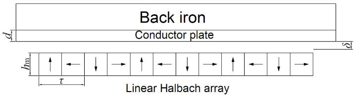
Structure of permanent eddy current brake using linear Halbach array.
When the back iron and conductor plate move together over the Halbach array, according to the law of electromagnetic induction, induced eddy current will be generated in the conductor plate. Then the induced eddy current generates a secondary magnetic field, which in turn weaken the primary magnetic field. The braking force is produced by the interaction between the eddy current and the primary magnetic field.
Figure 2 shows the simplified 2-D analytical model, neglecting end effects and assuming the current density distribution being supposed directed only along the z axis. The computational domain is divided into five regions. Region 0, 2 are air, region 1 is linear Halbach array, region 3 is conductor plate and region 4 is back iron. The thickness of the region 4 is assumed to be infinite in this paper; for it has been observed that this approximation does not modify the device performance evaluation [15]. The problem is descried by a rest reference frame associated with the linear Halbach array.
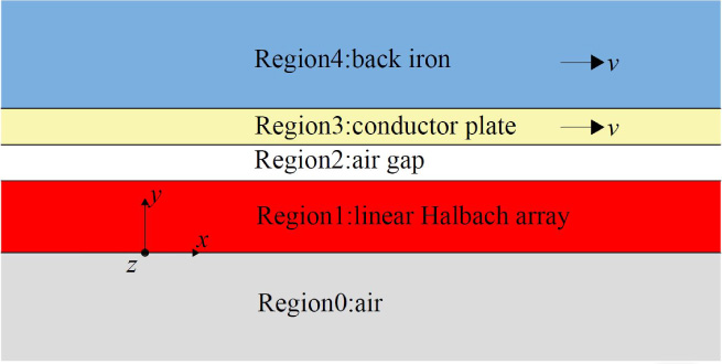
Simplified 2-D analytical model.
The geometrical parameters and their values of the permanent magnet eddy current brake are reported in Table 1.
Parameters of the eddy current brake used in the calculations
The governing equations are derived from Maxwell’s equations
Assuming all the materials are isotropic, the equation describing the properties of the materials are
The conductor plate and back iron moves together at velocity v, then the contribution of Lorentz force should be added to the right end of (4).
The magnetic flux density
To simplify the problem, we can assume that all the electromagnetic quantities are periodic with 2τ (one period of Halbach array), which means
Regions 0, 2, 4: The conductivity in the air and the back iron is zero. And the governing equations can be written as
Region 1: The constitutive relation of permanent magnet can be described by residual magnetic flux density
The governing equations is
Region 3: The conductivity of this region is not zero and the conductor plate is moving at velocity v, so the governing equation can be derived as
The first term on the right relates to induced electromotive force, and the second term on the right relates to motional electromotive force. In the quasi-static condition, the induced electromotive force is ignored, and (13) can be simplified as
The general solution of each region are
The general solution contains total number of 10 constants, which are determined by means of the underlying boundary conditions.
The magnetic vector potential has to vanish at infinity, such that
Therefore,
On the boundary of adjacent regions, the normal component of the magnetic flux density B
y
is continuous, and the tangential component of the magnetic field intensity H
x
is continuous. Hence, the boundary equations on the interfaces are given by
It is possible to calculate the eddy currents induced in the conductor from the field solution:
The braking force
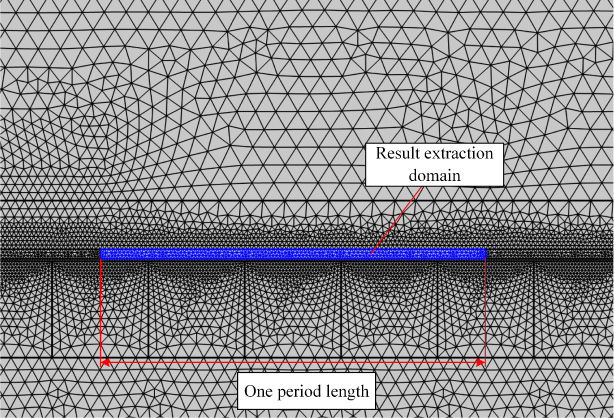
The FEM analysis is implemented using the COMSOL Multiphysics software. The finite element model is set up in the same way from Fig. 2, assuming the z direction is infinite and using a rest reference frame associated with the linear Halbach array. In this way, eddy current is modeled by the
Simplified 2-D analytical model.
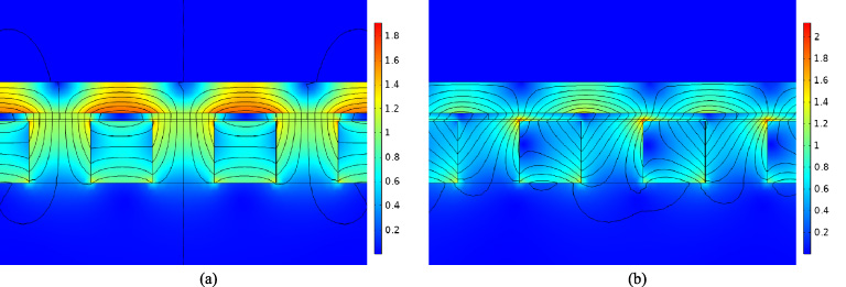
Magnetic flux density distribution at the speed of 0 m/s (a) and 15 m/s (b).
In Fig. 4, we show the magnetic flux density distribution with a speed of 0 m/s and 15 m/s. Figure 5 shows the components of the magnetic flux density along the x axis at a height of y = h m + δ + d∕2. It can be observed that a very good agreement between the analytical and the numerical results. The velocity increases from 0 m/s to 10 m/s, and the magnetic flux density is distorted in the direction of z axis.
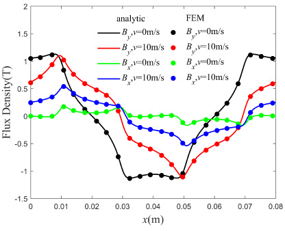
Components of the magnetic flux density computed analytically and by means of the FEM along the x axis at in case of quasi-static condition.
The braking force characteristic calculated by the analytic method and the FEM are represented in Fig. 6. It can be seen that the analytical method has good correlation with the FEM, verifying the accuracy of the analytical model and the finite element model. And the difference between analytical and FEM solutions can be quantified by means of the normalized root mean square deviation (NRMSD) over N data points [13]. The NRMSD of braking force over N = 301 data points is only 0.47%. As expected, for low speed, a linear dependence of the braking force can be observed. In this phase, the back reaction of induced eddy currents is negligible. However, if the conductor plate speed increases, the magnetic flux density inside the conductor plate decreases and the resulting braking force decreases.
When the speed of the conductor plate increases, the induced eddy current inside the conductor plate also changes. The interaction between the secondary magnetic field excited by the changing induced eddy current and the primary magnetic field makes the magnetic flux density in the conductor plate change accordingly, thus generating the induced electromotive force. When the speed changes rapidly, that is, the acceleration is large, the induced electromotive force cannot be ignored.
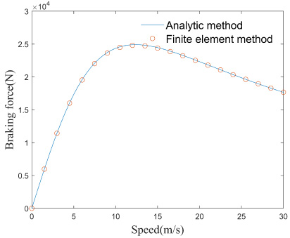
Braking force–speed characteristic.
The governing equation of region 3 is described by (5), and the eddy currents induced in the conductor plate is given as
In this paper, the braking characteristics of eddy current brake with high acceleration are solved by FEM. The finite element model is the same as described in the previous section, but the acceleration is large and
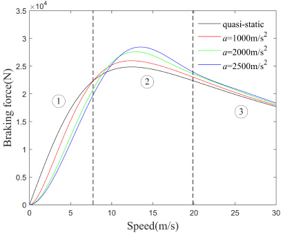
Braking force–speed characteristic for different acceleration.
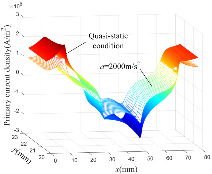
Primary eddy current density distribution in case of quasi-stats condition and a = 2000 m∕s2 at the speed of 5 m/s.
Figure 7 shows the braking force curves of eddy current brake with different constant accelerations. It can be observed that the braking force curves can be divided into three phases. Phase 1 is front lag phases, phase 2 is transition phase and phase 3 it back lag phase. In the lag phases, the braking force with high acceleration lags behind that under quasi-static condition, and there is a transition phase near the critical speed. The greater the acceleration, the more obvious the lag, and the bigger the peak value of the braking force in the transition phase. When the acceleration is 2500 m∕s2, the peak value of braking force increases by 14.5% compared with that of quasi-static condition. An explanation regarding this phenomenon is given in the following.
In the lag phases, the secondary current generated by induced electromotive force impedes the change in primary current. The primary current density distribution at speed of 5 m/s are shown in Fig. 8. The distribution of primary current density in case of quasi static and a = 2000 m∕s2 is obviously different. For more detailed explanation, the curves of Electric current density in the z direction and magnetic flux density in the y direction B y at the point (0, h m + δ + d∕2) are shown as Fig. 9. It can be seen that the secondary current always hinders the change of the primary induced eddy current, due to the effect of induced electromotive force B y lags in the phase 1 and phase 2. The primary current density is related to the secondary current density and the contribution of Lorentz force while the contribution of Lorentz force is related to the B y and speed. In phase 1, B y lags behind, but the speed is small, so the secondary eddy current plays a major role. In phase 2, as the speed increases, the contribution of Lorentz forces plays a major role, resulting in the peak value of the braking force bigger than that can be achieved under quasi-static condition. In phase 3, B y almost doesn’t lags, and the secondary current causes the lag of primary induced eddy current. Figure 10(a) shows the magnetic flux density distribution in case of quasi-stats condition at the speed of 7.5 m/s, while Fig. 10(b) shows the magnetic flux density distribution in case of a = 2000 m∕s2. Consistent with the above explanation, the magnetic flux density inside the eddy current brake under high acceleration is slightly greater than that under quasi-static conditions.
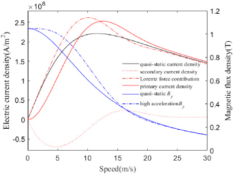
Electric current density curves and magnetic flux density curves at a point (0, h m + δ + d∕2) on the conductor plat in case of a = 2000 m∕s2.
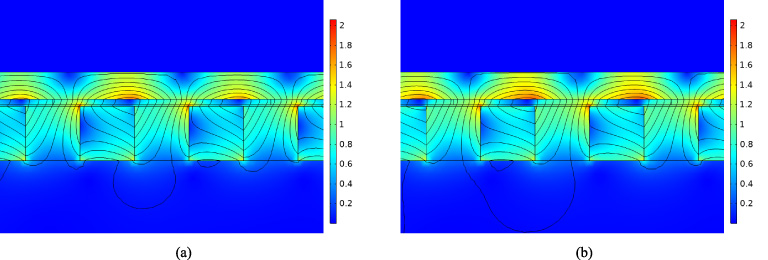
Magnetic flux density distribution in case of quasi-stats condition (a) and a = 2000 m∕s2 (b) at the speed of 7.5 m/s.
In this section, the influence of several parameters on braking force is investigated by FEM.
Influence of conductor plate thickness
The secondary magnetic field generated by primary current will suppress the primary magnetic field. The increase of conductor plate thickness will enhance the suppressing effect at the same velocity. So the eddy current brake will reach the critical speed earlier, as shown in Fig. 11, which will reduce the peak value of the braking force. Different form the quasi-static condition, the peak value of the braking force is almost the same for different conductor plate thickness in case of high acceleration. This indicates that the thickness of conductor plate greatly affect the effect of acceleration (induced electromotive force) on braking force.
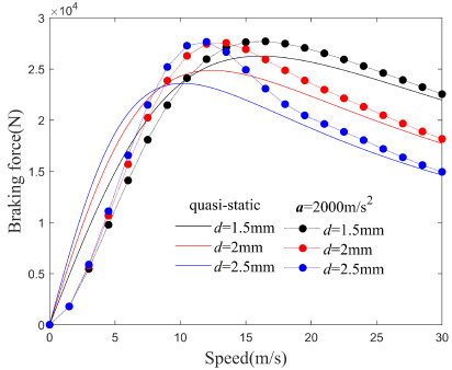
Braking force–speed characteristic in case of quasi-static condition and a = 2000 m∕s2 for different conductor plate thicknesses.
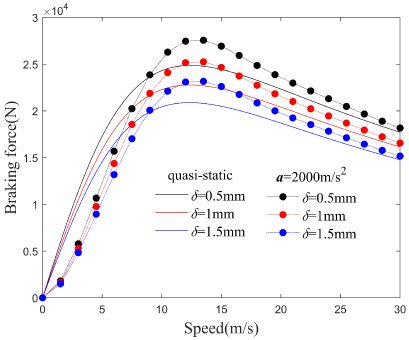
Braking force–speed characteristic in case of quasi-static condition and a = 2000 m∕s2 for different air gap lengths.
In Fig. 12, the braking force curves are shown for different air gap lengths δ. It can be seen that an increase in δ leads to lower braking force due to the decrease in magnetic flux density. However, the critical speed has barely changed for different air gap length. And the effect of acceleration on braking force has little relation with air gap length.
Influence of conductivity of the conductor plate
As shown in Fig. 13, the slope of the braking force increases, the critical speed decrease and the effect of acceleration is stronger as the conductivity of the conductor plate increases. Under quasi-static condition, the peak value of the braking force changes little with the conductivity of the conductor plate, but after considering the effect of acceleration, the peak value of the braking force increases with the increase of the conductivity of the conductor plate. It can be observed that the conductivity of the conductor plate greatly affects the resulting braking force profile due to the complex interaction between the primary and secondary currents.
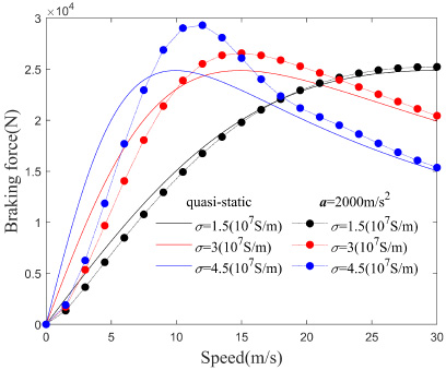
Braking force–speed characteristic in case of quasi-static condition and a = 2000 m∕s2 for different conductivity of the conductor plate.
Figure 14 shows the braking force characteristic curves with different heights of the permanent magnets. As we can observed, the heights of the permanent magnet have a small impact on the critical speed, while the heights of the permanent magnet has a great impact the slope and peak value of the braking force. And the effect of acceleration does not significantly enhanced as the height of permanent magnet increases.
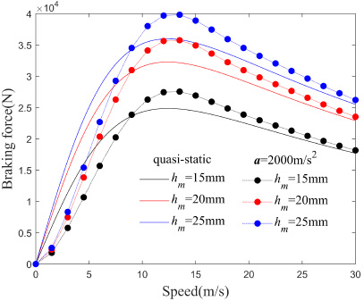
Braking force–speed characteristic in case of quasi-static condition and a = 2000 m∕s2 for different heights of the permanent magnets.
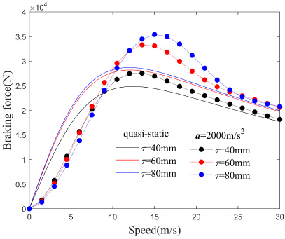
Braking force–speed characteristic in case of quasi-static condition and a = 2000 m∕s2 for different lengths of the permanent magnets.
In Fig. 15, when the length of permanent magnets increases from 20 mm to 30 mm, the peak value of the braking force increases significantly. Meanwhile when the length of permanent magnet increases from 30 mm to 40 mm, the peak value of the braking force hardly changes. This is the result of an interaction of reduced magnetic flux density and increased eddy current region. And it can be seen that the peak value of the braking force increases due to the effect of acceleration, when the length of permanent magnets increases from 30 mm to 40 mm. This indicates that the increase of eddy current region enhances the effect of acceleration on braking force.
Conclusion
With the development of eddy current brakes, the application range of eddy current brakes is increasing. In some industrial applications, the moving part has greater acceleration. Under this situation, the back reaction of the conductor and its reactance will cause phase shifts, lower braking forces at low speed [16], higher braking forces after critical speed, and greater peak value. This should be taken into account when evaluating the dynamic characteristics of high acceleration systems. Otherwise, the performance of the eddy current brake will be different from what is expected. It may even cause damage to the device due to the larger peak value of the braking force than expected. It is necessary that the effect of acceleration on braking force should be considered of high acceleration systems to provide more accurate predictions.
This paper builds a quasi-static analytical model of the permanent magnet eddy current brake, and provides analytic expressions for magnetic vector potential. The results from finite element model agreed with the results from the analytical model that verify the accuracy of the two models. When the conductor plate is moving at a high acceleration, the complex interaction between the primary current and the secondary current cannot be ignored. The braking force characteristics under quasi-static and high acceleration are compared. Moreover, parametric analysis was provided to give useful information to the designer of the eddy current brake. The effect of acceleration is strongly dependent on thickness and conductivity of the conductor plate and length of the permanent magnets. However, the air gap length and the height of the permanent magnets have a small impact on the effect of acceleration.
Footnotes
Acknowledgements
This work was supported in part by the National Natural Science Foundation of China under Project 11572158 and 51705253, and the Postgraduate Research & Practice Innovation Program of Jiangsu Province under Grant KYCX19_0334.
Appendix
The expressions of constants