
Abstract
Aiming at slippage and belt breakage of large mechanical conveyor belts, a new type of water-cooled permanent magnet brake (WPMB) is proposed. In order to determine the braking performance of WPMB, a multi-physics coupling model and analysis method of magneto-thermal-structure are built. The braking torque and temperature characteristics of WPMB under different working conditions are obtained. Based on the magnetic vector potential equation, an electromagnetic eddy current model is established, and the variation trend of braking torque with speed is predicted. The temperature field model is built based on the equivalent thermal network method. Using multi-field coupling analysis method and 3-D FEM, the influence factors of WPMB braking torque are analyzed. Two test prototypes with rated speed of 78 rpm, braking torque of 3000 N⋅m are designed and developed. Braking torque characteristic tests and magnetic shielding characteristic tests at different speeds and continuous braking characteristic test are carried out. Experiments show that the proposed method provides very practical results to ensure the continuous and stable operation of WPMB.
Introduction
With the development of the transportation industry, as a belt conveyor for conveying goods, the conveying distance becomes longer, the load change increases, the continuous working time becomes longer, and the friction torque is often attenuated, resulting in belt slippage, belt breakage and other problems [1,2]. Eddy current brake is an electromagnetic device that uses Faraday’s law of electromagnetic induction to convert the kinetic energy of a moving object into thermal energy, thereby generating braking torque [3–5]. Eddy current brakes last longer due to the absence of mechanical contact, wear and noise. It has been used in high-speed train braking systems [6], heavy vehicle auxiliary braking [7], space docking mechanisms [8] and other industrial fields. In eddy current brakes, the magnetic field source can be generated by winding coils or permanent magnets [9]. Electrically actuated eddy current brakes require additional power and cause significant energy losses. However, the permanent magnet eddy current brake has the advantages of no power supply, high efficiency, and the ability to generate a large braking torque. Therefore, it is more widely used [10,11].
Based on the difference of brake structure, it can be divided into two types: disc eddy current brakes and cylinder eddy current brakes. H.Waloyo et al. proposed an axial flux disc type eddy current brake. Heat sinks are assembled on the conductor back iron to dissipate heat through air cooling, and the braking torque can be controlled by changing the gap between the permanent magnet and the conductor [12]. However, when this brake structure continues to brake for a long time, the heat dissipation method of air cooling will cause the temperature of the eddy current disc to rise too fast, and in the non-working state of the eddy current brake, the magnetic field cannot be completely shielded, and flux leakage torque will be generated. Ye et al. proposed a water-cooled cylindrical high-speed (speed greater than 500 rpm) eddy current brake for heavy vehicles. By controlling the overlap area between PM and stator, the braking force can be changed [13]. But this brake structure is less torquey at low speeds (especially below 100 rpm).
Like general electromagnetic devices, eddy current brakes can be studied by finite element method (FEM) [14] or analytical methods [15]. Finite element method (FEM) can be used to calculate eddy current brakes with complex structures, but the single calculation time is long [16–18]. This analytical method is flexible, fast and quite accurate, and can be used for the preliminary design of eddy current brakes [19]. Dai et al. proposed a 2D analytical model for predicting of the magnetic field in permanent magnet eddy current couplings with a slotted conductor topology, transforming the conductor eddy current problem into a Helmholtz equation solution in a time-harmonic field, however, two dimensional analytical models can lead to inaccurate results for edge effects related to 3D geometry, and satisfactory results can only be achieved under certain restricted conditions [20]. Wang et al. uses the magnetic vector potential formula to derive the braking torque formula of the disc permanent magnet eddy current brake based on the 3-D Cartesian coordinate system. However, in the solution, the demagnetization effect of temperature on the permanent magnet and the effect of thermal deformation on the structure of the brake are ignored in the solution [21].
In this paper, a new type of water-cooled permanent magnet brake (WPMB) for belt conveyors is designed, which has the advantages of low operating temperature, outstanding continuous operation stability, complete shielding of the magnetic field during non-operation, and high torque at low speed. Based on the introduction of the structure and principle of WPMB, the actual structure is equivalent to a linear structure by applying the assumption of average radius and equivalent cuboid, and its electromagnetic field is solved by using the 3D Cartesian coordinate system and the magnetic vector potential formula, and considering the coupling effect between the temperature field and the structure field of the WPMB, the braking performance of the WPMB is analyzed. Two brake prototypes are trial-manufactured and tested under various working conditions of WPMB. Experiments show that the multi-physics coupling analysis method is in good agreement with the 3-D FEM method and the experimental results.
Structure and working principles
Figure 1 shows the structure of the conventional air-cooled permanent magnet brake (APMB) of disc and the new WPMB of cylinder. In the APMB, the PM are evenly distributed on the rotor, and there is a certain gap between the stator with heat sink and the rotor, and the braking torque can be controlled by controlling the axial gap of the stator and rotor [10]. Forced air-cooled convection cannot take away a large amount of heat in a short period of time, and in the non-working state, flux leakage torque will still be generated between the stator and the rotor. The new WPMB adopts water-cooling heat dissipation, which can greatly improve the heat dissipation effect, and the PM is pulled into the shielding rotor to achieve the effect of completely shielding the magnetic field. Figure 2 shows the working principle of the WPMB. When the WPMB is in operation, the PM is pulled into the conductor by the controlled motor. The PM and conductor overlap, the conductor and conductor back iron cut the magnetic induction lines from the PM. According to Lenz’s law, eddy currents and braking torques are induced in the conductor and conductor back iron. It converts the kinetic energy of the WPMB into thermal energy, which is carried away by cooling water. When the WPMB needs to change the braking torque, the PM is pushed axially by the control motor, and the braking torque is changed by adjusting the intersection area between the PM and the conductor. When the PM fully overlap the shielded rotor, the WPMB remains inactive. Since the shielded rotor and the PM do not move relative to each other, no eddy currents are generated on the shielded rotor. At this time, WPMB does not output braking torque. The main geometrical parameters of WPMB are shown in Table 1.

Structure of different brakes. (a) APMB. (b) WPMB.

2-D schematic diagram of WPMB.
Geometric parameters of the WPMB
The flow chart of the proposed method is shown in Fig. 3. The method has three stages, magnetic analysis, thermal analysis and structural analysis. In the magnetic analysis, the actual structure of WPMB is equivalent to a linear analysis 3-D model, the electromagnetic force and torque of WPMB are solved by using the magnetic vector potential formula. When solving, the B-H curve, the PM hysteresis curve, and the conductivity of the conductor are defined as a function of temperature. In the thermal analysis, an equivalent thermal network model is established, and the temperature rise of all components are calculated through the heat transfer equation. In the structural analysis, the deformation caused by the thermal stress and the impact of the mechanical load such as the vibration load and the press load generated by the WPMB in the working state on the structure are mainly considered.

Flow chart of coupled analysis method of magneto-thermal-structure.
In order to simplify the analytical solution of the 3-D motion eddy current problem, the following assumptions are made: The thickness of the PM back iron is large enough to avoid magnetic saturation, and its permeability is considered to be infinite. The permeability of the conductor is equal to the air permeability μ0. The equivalent average permeability μ
eq1, μ
eq2 and μ
eq3 are used to represent the permeability of the conductor back iron, the housing stator and the shielded rotor, respectively, in order to consider the saturation behavior.
According to the above assumptions, the WPMB nonlinear moving conductor eddy current problem is transformed into a linear problem for solving, and the permanent magnet is equivalent to a rectangular magnet with the same cross-sectional area and thickness, and create a 3D solution model as shown in Fig. 4.

Linear analytical 3-D model of electromagnetic field.
Due to the symmetry of the linear model, the solution model for the working and non-working states of the WPMB is divided into eight solution areas: I conductor back iron, II conductor, III air gap 1, IV PM, V housing stator, VI air gap 2, VII shielded rotor, VIII air gap 3. Γ1, Γ12, Γ23, Γ34, Γ4, Γ5, Γ56, Γ67, Γ78 are the interfaces or boundary interfaces between adjacent regions, respectively.
Based on Maxwell’s equations and introducing the magnetic vector potential
Then the governing equation of each region is expressed as:
Region I: The magnetic permeability of the conductor back iron region is μ
eq1, and its material is a conductive material. The current density
Therefore, the region equation can be expressed as:
Similarly, region V and region VII can be written as:
Region II: The magnetic permeability μ
c
of the conductor region is approximately equal to the air permeability μ0. The material is conductive material, and the current density
Considering that the eddy current is mainly generated on the conductor when the WPMB is working, a large amount of heat will be generated on the conductor. At this time, the electrical conductivity of the material will be changed as the temperature. Therefore,
When the PM temperature changes, the change in magnetic field strength should be considered.
Equation (6) can be modified as:
Therefore, the equation of this region can be expressed as:
Region III: The conductivity of the air gap 1 region is 0, and the equation for this region can be expressed as:
Similarly, region VI and region VIII can be written as:
Region IV: The governing equation of the permanent magnet region can be expressed as:
In order to simplify the problem, assuming that the above parameters are all based on the pole pitch τ as the period, and taking into account the n-th harmonic in the x direction and the k-th harmonic in the z direction, the magnetic vector potential
Region I, Region V and Region VII:
The analytical model satisfies the following tangential and normal boundary conditions:
The magnetic flux density can be calculated.
Therefore, the eddy current loss can be calculated.
Since WPMB has no mechanical loss, electromagnetic force and electromagnetic torque are also braking force and braking torque, which can be calculated by the following formulas:
When WPMB is working, eddy currents are mainly generated on the conductor and the conductor back iron. The eddy current loss will generate a large amount of heat energy, which will increase the temperature of WPMB. The temperature rise will change the characteristics of the material, and reduce the braking torque of the WPMB.
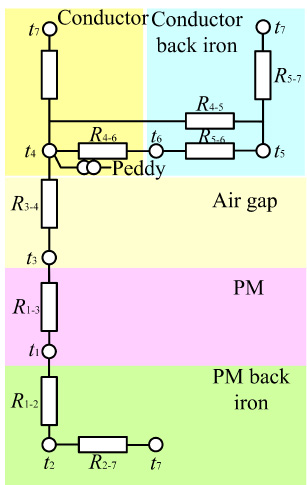
Equivalent thermal resistance network of WPMB.
In Fig. 5, t
1, t
2, t
3, t
4, t
5, t
6, t
7 are the node temperatures of the PM, the PM back iron, the air gap 1, the conductor, the conductor back iron, the cooling water, and the ambient temperature, respectively. The conduction thermal resistance is R
1−2, R
4−5, and the calculation formula of the conduction thermal resistance is:
The convective thermal resistance is R
1−3, R
3−4, R
4−6, R
5−6, R
2−7, R
4−7, R
5−7, and the calculation formula of convective thermal resistance is:
For air-cooled and water-cooled, the calculation of the convective heat dissipation coefficient is different. The convective heat dissipation coefficient of R
1−3, R
3−4, R
2−7, R
4−7, R
5−7 is a function of air velocity on the surface:
The convective heat dissipation coefficient of R
4−6 and R
5−6 is a function of the strong turbulent flow of cooling water in the water channel [9]:
For steady-state temperature analysis, the temperature rise of each temperature node of the equivalent thermal network is:
The deformation of the mechanical structure will affect the distribution of the WPMB magnetic field, which will lead to the change of the eddy current braking force. At the same time, the eddy current braking force may also damage the mechanical structure, so the coupled analysis of the structure is necessary [23].
When WPMB is working, due to the uneven heat dissipation in the water channel, thermal stress will be generated on the conductor and the conductor back iron. At the same time, the electromagnetic force and mechanical load are generated during work. The mechanical loads include vibration load and press load, among others. That will have some impact on the structure of the brake.
In this paper, the deformation of the conductor and the conductor back iron is small, which can be considered as plastic deformation.
The physical equation of thermal stress is:
The thermal deformation caused by the temperature difference is:
Under the combined action of thermal force and mechanical force, the equation of stress and strain of WPMB can be expressed as:
Influence factor of WPMB braking torque
In order to analyze the influencing factors of WPMB braking torque, a 3-D FEM multi-field coupled analysis is also performed in this work to evaluate the accuracy of the proposed method.
Use JMAG-Designer finite element analysis software to solve the electromagnetic model. Figure 6 shows the electromagnetic model and mesh of WPMB. By using rotational anti-periodic boundary condition, the electromagnetic model is 1/18 of the entire model. The air domain of the model is 1.3 times that of the electromagnetic model in the radial direction and axis direction. Considering the skin effect of eddy current, a three-layer boundary layer mesh is set, and the thickness of the boundary layer mesh is the eddy current equivalent skin depth, grid element size is 2 mm, the total number of nodes is 142234, and the number of elements is 580511. Figure 7 is the electromagnetic field vector distribution diagram and the eddy current distribution diagram.
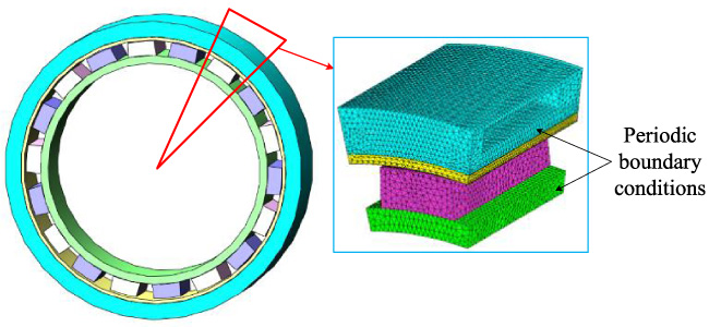
Electromagnetic model and mesh of WPMB.
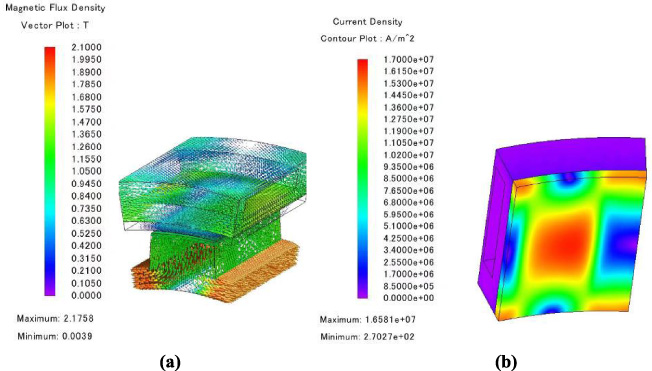
Electromagnetic field analysis results. (a) Vector distribution diagram. (b) eddy current distribution diagram.
Using the ANSYS Fluent module to solve the temperature model, Fig. 8 shows the temperature model and mesh of the WPMB. Due to the symmetry of the model, only 1/2 of the entire area is analyzed. The mesh size is 2 mm, the inflation boundary is set as the water inlet and outlet, the maximum layers is 5, the total number of nodes is 278640, and the number of elements is 810436. The rotation period boundary condition is used, the inlet boundary condition is mass flow, the outlet boundary condition is normal atmospheric pressure, the diameter of the inlet and outlet pipes is 40 mm, and the length is 120 mm, and the thermophysical properties of the material change with temperature. It is assumed that the heat generated by eddy current losses is only at the skin effect depth.
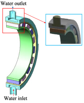
Temperature model and mesh of WPMB.
Use the ANSYS Static Structure module to solve the structural model. The structural model and its mesh are consistent with the temperature model and mesh, which will not be described here. The solution results of Fluent and JMAG-Designer, as well as the pressure loads generated during the actual work of WPMB, are attached to the structural model solution.
The calculation time of the analysis method proposed in this paper (1 point 8 seconds) is much smaller than that of using 3-D FEM analysis on a computer with an Intel TM core i7-11700, a speed of 2.5 GHz and a RAM of 16 GB (three-field coupling 1 point 53 minutes).
The calculation results of the proposed multi-physics coupling analysis method are in good agreement with the results of the 3-D FEM method, and the relative error is basically less than 5%. The calculation results of the proposed multi-physics coupling analysis method are less than the 3-D FEM analysis method. This is mainly because the influence of the temperature field on the electromagnetic field of the 3-D FEM cannot be updated in real time, which leads to the hysteresis of the electromagnetic field.
For the WPMB whose overall size is determined, the parameters affecting its braking performance mainly include the material of the conductor, the thickness of the PM, and the air gap between the PM and the conductor. The control variable method is used to analyze the above parameters in detail.
It can be seen from Fig. 9 that the conductor material has a great influence on the braking characteristics of WPMB. Compared with 20 steel and yellow copper, red copper and pure aluminum materials can obtain larger torque at low speeds. This is mainly due to the different electrical conductivity of the materials. The properties of various materials are shown in Table 2.

The influence of conductor materials on braking torque.
Properties of different materials.
The section of the PM is fixed, and the increase in thickness will increase the magnetic energy, which is beneficial to improve the braking force, but the corresponding PM cost is also higher. Figure 10 shows the braking characteristics of PM with different thicknesses when using conductor-aluminum at different rotational speeds. As can be seen, the braking torque increases with the increasing PM thickness. However, the increasing trend gradually decreases, the braking force per unit volume shows a downward trend, and the cost performance of permanent magnets gradually decreases.

The influence of PM thickness on braking torque.
Figure 11 shows the air gap and braking torque curves when the speed is 78 rpm, conductor-aluminum and the thickness of PM is 25 mm. As the air gap increases, the air gap magnetoresistance keeps increasing, the magnetic induction and eddy current of the conductor and the conductor back iron decrease, the braking torque of the WPMB decreases continuously.

The influence of the air gap between the PM and the conductor on the braking torque.
In order to further verify the method proposed in this paper, based on the data in Table 1, two WPMBs with a rated speed of 78 rpm and a torque of 3000 Nm were developed (The main geometrical parameters of WPMB are shown in Table 1). Conductor back iron, PM back iron, shielded rotor and housing stator were all made of 20 steel, PM was made of Nd-Fe-B 50, and conductors were made of red copper and pure aluminum. Brakes with pure aluminium conductor was first tested. The test bench is shown in Fig. 12, including drive motor, reducer, speed torque sensor, temperature sensor, bearing box, WPMB and control motor. PM rotor and stator with aluminum conductor are shown in Fig. 13.

Test bench for WPMB.

Parts of WPMB. (a) PM rotor. (b) Stator with aluminum conductor.
Three working conditions:
(1) Braking torque characteristic test at different speeds
Figure 14 shows the braking torque characteristic curve at different speeds. The maximum error between the result of the experimental and the result of the proposed method is 4.4%. There may be two reasons for this. One is the problem of converting WPMB into an equivalent straight line in the calculation of the electromagnetic field. Another is the equivalent thermal network model in the calculation of the temperature field calculation assumes that the temperature distribution of each part is uniform, and the temperature distribution in the actual test is stepped, which leads to a large test value.

Braking torque characteristics curve.
(2) Magnetic shielding characteristic test
Figure 15 shows the magnetic shielding characteristic curve. It can be seen that the temperature rise and structural deformation of WPMB are very small when WPMB is in a non-working state, and the results calculated by the three methods are very close at this time. In addition, the magnetic leakage torque increases with the increase of the speed. When the speed increases to 200 rpm, the magnetic leakage torque is only 3 N⋅m, which is only 0.08% of the working torque, and the overall shielding effect is outstanding.
(3) Continuous braking characteristic test
The test conditions are as follows: the rotational speed is 78 rpm, the air gap is 3 mm, and the continuous braking time is 60 min. Figure 16 shows the characteristic curve of continuous braking for 60 minutes. It can be seen that as the braking time increases, the temperature of the conductor continues to rise, and the braking torque continues to decrease. But the decreasing trend gradually eases, indicating that the WPMB has reached the temperature equilibrium. After 60 minutes of braking, the temperature of the conductor back iron rises to 44 °C, and the braking torque decreases 12%.

Magnetic shielding characteristic curve.

60 min characteristics curve of conductor-aluminum continuous braking.
After completing the experimental study of various working conditions of WPMB, it was found that the aluminum conductor is broken, as shown in Fig. 17. 3-D FEM is used to analyze the stress of the brakes of different conductors at 78 rpm for 60 min. The stress cloud of conductor and conductor back iron is shown in Fig. 18. As can be seen from Fig. 18(a), since there are bolts installed on one side of the water channel, the water channel is asymmetrically distributed, which causes the maximum stress to be distributed on one edge of the aluminum conductor, and the maximum value is 166 Mpa, which exceeds the strength limit of pure aluminum. It can also be seen from Fig. 18(b) that when the conductor material is red copper, the maximum stress value is still distributed on the edge of the conductor, and the maximum value is 220 Mpa, which does not exceed the strength limit of red copper.
As shown in Fig. 19, the conductor material was replaced with red copper, and the WPMB was tested again to verify the above analysis. The test conditions are as follows: the rotational speed is 78 rpm, the air gap is 3 mm, and the continuous braking time is 120 min. Figure 20 shows that the conductor and PM temperatures stabilized after 45 minutes. The temperature of the PM is lower than that of the conductor. The maximum temperature of PM can reach 58 °C, and the maximum temperature of conductor can reach 65 °C. Braking torque drops 7% in 120 minutes. After the test is completed, the red copper conductor did not damaged.

60 min characteristics curve of conductor-aluminum continuous braking.

Stress cloud chart. (a) Aluminum. (b) red copper.

Conductor-red copper of WPMB.

120 min characteristic curve of conductor-red copper continuous braking.
This paper proposes a new type of WPMB for belt conveyors. By considering the temperature dependence of electrical conductivity and permeability of materials and the influence of structural deformation on the working characteristics of WPMB, a coupled analysis model of magnetic-thermal-structural multi-physics is established. The multi-physics coupling method proposed in this paper and 3-D FEM coupling method are used to analyze the influence of different factors on the WPMB braking torque. Experiments are carried out on WPMB whose conductors are made of pure aluminum material and red copper material, the braking and temperature characteristics of WPMB under different working conditions are analyzed. The proposed multi-physics coupling analysis method and 3-D FEM coupling method are in good agreement with the experimental data of WPMB. This verifies the computational accuracy of the proposed multi-physics coupling method. At the same time, the proposed multi-physics coupling method can save a lot of time for the study of similar WPMB, and is very suitable for the analysis, design and optimization of WPMB.
Footnotes
Acknowledgements
This work is supported by the National Natural Science Foundation of China under Project 51777003.