
Abstract
A linear generator system based on a free-piston engine is expected to be a highly efficient power-generation engine for series hybrid vehicles. However, the engine generator must produce in a limited installation space the very high power required to drive a car. Consequently, considering the car-mounting situation, higher power density is required by means of reduced generator size and higher efficiency. In this paper, a cylindrical double-stator linear synchronous generator with opposing permanent magnets is used for free-piston engine. The double stator realizes smaller size, and using opposing magnets achieves a larger thrust constant than that with a single stator. In a finite-element analysis, the high-efficiency area is expanded compared to a surface-magnet type of the same size. Furthermore, this paper clarifies the effectiveness for improved power density with maximum-generation control in a simulation of a dual-sided engine model.
Keywords
Introduction
The number of series hybrid vehicles (SHVs) equipped with engine generators has increased in recent years [1,2]. In an SHV, fuel energy is converted into electrical energy by means of a crank engine, and a rotary generator is used to drive the vehicle’s running motor. This system consumes electricity near the generator, thereby realizing local power production. In addition, high generation efficiency is achieved by using the rotary generator to realize constant-output operation. However, because this system has a crank mechanism, the mechanical loss is huge. Therefore, the next type of automobile power-generation engine is expected to be the free-piston engine linear generation system (FPEG), which can achieve high efficiency and improved performance [3–8].
The FPEG comprises a free-piston engine and a linear generator. The free-piston engine is a reciprocating internal combustion engine. A linear generator coil is arranged around the free-piston to extract electricity, and a permanent magnet is attached to the free-piston. The linear generator produces electrical power from the motion of the piston, and the braking thrust acts in the opposite direction to that of the piston motion. The free-piston is free to move without being fixed to the crank and is controlled by the braking thrust. Because the combustion energy is converted directly into electrical power without a crank mechanism, the mechanical loss is reduced by around 30% [9]. The engine structure is generally a single type in which the combustion chamber is arranged only one [10,11]. However, to increase output power density in an automobile context, a dual-type engine has been proposed for which combustion chambers are arranged in both sides [12,13]. The FPEG generates in a limited installation space the very high power required to drive a car, but higher output power density could be achieved by reduced generator size and higher efficiency.
We have previously reported on the design guidelines for a surface-permanent-magnet-type linear synchronous generator (SPM) for improved FPEG generation efficiency [14,15]. However, because it is necessary to attach a back yoke to the mover, and the size of the generator tends to be large in the SPM. The gap magnetic flux density cannot exceed the residual magnetic flux density of the permanent magnet. This makes it difficult to improve the thrust constant for higher efficiency even if more magnets are used. Therefore, we proposed a cylindrical double-stator linear synchronous generator with opposing permanent magnets (DS-OPM) [16]. The double stator eliminates the back yoke of the mover and is expected to achieve smaller generator volume than that with a single stator.
The DS-OPM is of the homopolar opposite type, and the magnet is sandwiched inside yoke composed of electromagnetic steel sheet. The thrust constant is thus improved by an increased gap flux density, and the area of high-efficiency generation is expanded. In the present paper, we consider a double-stator linear synchronous generator with a surface magnet type (DS-SPM) of the same size to clarify the DS-OPM effect for improved generation efficiency. We clarify the effectiveness of the DS-OPM for improved power density with maximum-generation output control by considering the efficiency map in a simulation of a dual-sided engine model.
Principle of FPEG
Physical models
Figure 1 show physical models of the dual-sided engines in the FPEG. The main body of the former comprises a combustion chamber, a linear generator, and a spring chamber, while the latter comprises a left-hand combustion chamber, a linear generator, and a right-hand combustion chamber. In the dual type, two-stroke engines are provided on the left and right. In the single-engine type, it is necessary to generate energy in one combustion chamber, but in the dual type it is possible to disperse the energy into two. Therefore, there are high expectations for downsizing and improved thermal efficiency. A permanent magnet is attached to the free-piston, and a coil is arranged in the stator. This is a permanent-magnet-type linear synchronous machine [17].
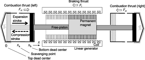
Physical models of free-piston engine linear generation system (FPEG).
The free-piston reciprocates by the left combustion thrust F cl, the right combustion thrust F cr, and the generation braking thrust F l. Movement of the free-piston from the left to the right correspond to an expansion stroke in the left engine and a compression stroke in the right engine. Conversely, movement of the free-piston from right to left corresponds to an expansion stroke in the right engine and a compression stroke in the left engine. Here referring to the left-hand engine, movement from left to right is defined as an expansion stroke, and movement from right to left is defined as a compression stroke.
Equation (1) describes the free-piston motion:
The top dead center (TDC) is left edge, and the bottom dead center (BDC) is right edge of the piston motion. The TDC and BDC is combustion point both side engines, respectively. As the free-piston moves to the BDC, we define x to be large. Also, the position at which the scavenging port opens is defined as the scavenging point x a , which is set to 0.07 m in this paper. After a combustion of the left-hand engine, the scavenging point is reached and the left-hand combustion chamber is released to atmospheric pressure. Simultaneously, the right-hand combustion chamber is shut off from atmospheric pressure and prepared for combustion. When the piston reaches the combustion start point of the right-hand engine, combustion starts. Thereafter, the right-hand combustion chamber is released to atmospheric pressure, and simultaneously the left-hand chamber prepares for a combustion. Power generation is continued by repeating this operation.
Figure 2 shows the circuit model. The circuit of the linear generator is assumed to be a three-phase synchronous machine, where e u , e v , and e w are the electromotive forces of each phase generated by the action of the free-piston, R a is the armature resistance, and L a is the armature inductance. The generation braking thrust acts depending on currents of the linear generator. The inverter is assumed to be a pulse-width modulation (PWM) control inverter. The currents of the linear generator are controlled by the signal fed to the gate of the inverter. The braking thrust is expressed by Eq. (2) as the sum of the thrusts generated in each phase, with the proportionality constant defined as the thrust constant K f . The generation braking thrust can be controlled by changing only the q-axis current considering the vector control [18] expressed by Eq. (3). The power generation and piston movement are controlled using a PWM inverter [15].
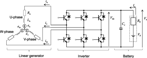
Circuit models of FPEG.
As just explained, we have
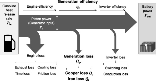
Figure 3 shows the energy flow of FPEG. First, the free-piston with a permanent-magnet is moved by the combustion power. The coil then generates electricity by induction and charges the battery that is used for the car-drive-motor. The fuel-combustion heat-release rate P
in is the input, and the battery electricity P
out is the output. The main losses are the engine loss, the generation loss, and the inverter loss. The main heat losses are the exhaust loss, cooling loss, and friction loss [19]. In the dual-sided engine, the linear generator does not require bearings because the free-piston is supported by the cylinders on both sides. Therefore, the friction loss occurs only in the engine. The generation losses are the copper loss Q
c
and the iron loss Q
i
. The main inverter losses are the switching loss and the conduction loss. The inverter has a high efficiency of over 98% [20]. In the present study, for simplicity we ignore the engine and inverter losses when discussing improvements in the power density of the generator. Therefore, the generation efficiency 𝜂
e
is calculated using Eq. (4), which (i) assumes an ideal switch for the inverter switching conducted herein and (ii) ignores the transient response. The effective combustion work W
p
is obtained by integrating the combustion thrust from the scavenging point to TDC. The piston power P
p
(Eq. (5)) is calculated by the combustion work dividing piston action frequency f to convert joules to watts. The power density 𝜌gen of the generator in the FPEG is expressed by Eq. (6). For high power density, we require both miniaturization and improved efficiency. As just explained, we have
Energy flow of FPEG.
Cylindrical double-stator type
An overview of the proposed double-stator-type FPEG is shown in Fig. 4. In the single-stator type, the armature comprises a yoke and a coil, and the mover comprises a permanent magnet and a back yoke. The single stator tends to be relatively large because it is necessary to provide the mover with a back yoke. By contrast, the mover is configured to be sandwiched between the outer and inner stator in the double-stator type. The working area is twice that of the single stator because two permanent magnets act per pole. This eliminates the back yoke and enables miniaturization [16].
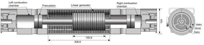
Structure of double-stator linear synchronous generator.
The positional relationship between the mover and the stator is shown in Fig. 5(a) for the DS-OPM (proposed) and in Fig. 5(b) for the DS-SPM (for comparison). The mover has the same poles of permanent magnets face each other, and electromagnetic steel plates are provided between the permanent magnets of opposite type. The specifications of are given in Table 1. Both generators have the same external dimensions and stator parameters to allow comparison of the thrust characteristics. The permanent magnet of the mover uses NEOMAX – 42AH (Hitachi metal, Ltd.). The armature inductance is the average value of one electrical angle cycle because of its dependence on the mover position.
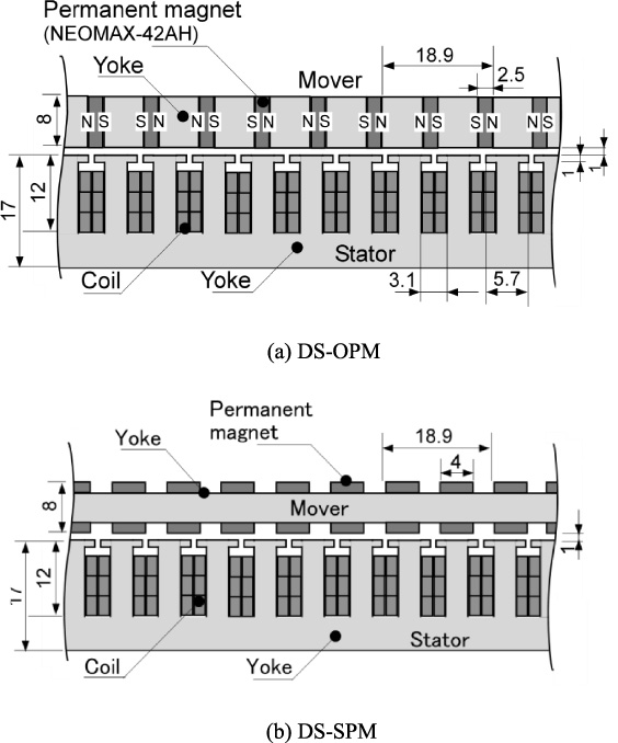
Positional relationship of mover and stator.
Specifications of generators
As expressed in Eq. (3), increasing the thrust constant reduces the current required to produce a given thrust. A higher thrust constant expands the high-generation-efficiency range by reducing the copper loss. To improve the thrust constant while keeping the stator parameters the same, we must improve the gap flux density between stator and mover. Figure 6 compares the expected magnetic flux in the two generators. The magnetic flux flows directly from the permanent-magnet to the stator, so the relative permeability is as low as 1.15 in the DS-SPM. Therefore, the upper limit of the gap magnetic flux density is the residual magnetic flux density of the permanent magnet. By contrast, in the DS-OPM the magnetic flux generated by the permanent magnet collides with the flux of the opposing permanent magnets and flows into the gap. Installing the magnetic steel sheet between the permanent magnets improves the relative permeability because the surface of the magnetic pole is no longer air but is now steel. Therefore, the gap magnetic flux density is improved, and the thrust constant is expected to be improved.
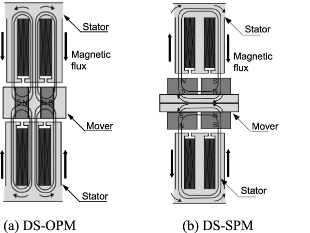
Comparison of magnetic flux.
We used the finite-element analysis software JMAG-Designer to evaluate the basic characteristics of the generators. Figure 7 shows the distribution of magnetic flux density with a current of 100 A. As expected in the DS-OPM, the magnetic flux from opposing permanent magnets collides and flux flows into the gap. The values of the gap magnetic flux density for the DS-OPM and DS-SPM are 1.1 T and 0.9 T, respectively. The gap magnetic flux density was improved by changing the structure of the mover to that in the DS-OPM.
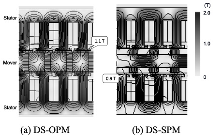
Finite-element analysis of magnetic flux.
Figure 8 shows the characteristics of the static thrust and current. Both generators maintain linearity up to around 100 A, but thrust saturation is observed thereafter. This is caused by the magnetic flux density saturation of the armature teeth. It is necessary to apply a thrust for which the magnetic flux density is not saturated. Below 100 A, the thrust constant was 18.5 N/A for the DS-SPM and 24.0 N/A for the DS-OPM, an improvement of around 30%.
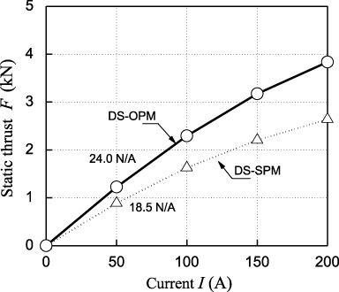
Characteristics of static thrust.
Figure 9 shows the iron-loss–speed characteristics. The iron loss is reduced at all speeds because the exposed area of the permanent magnet is relatively small in the DS-OPM. We consider the stator to be less susceptible to the influence of the spatial harmonics of the magnetic flux. The efficiency map of each generator is shown in Fig. 10. The maximum efficiency was 97.6% near 1800 N in the DS-OPM. For the DS-OPM, improving the thrust constant extends the high-efficiency region to higher thrust.

Characteristics of iron loss.
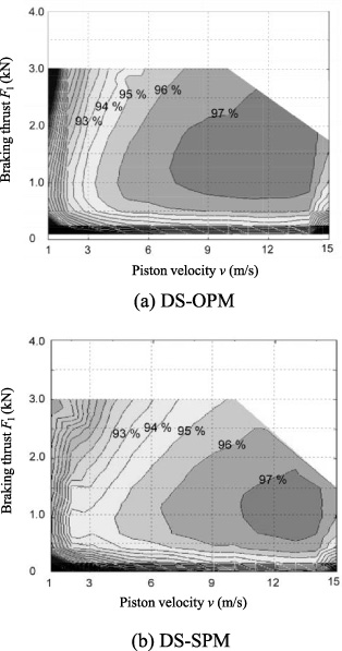
Efficiency map of generator.
Control for improving output
The generation efficiency of FPEGs tends to be lower than that of the rotary generators that are used in current SHVs. A combustion experiment is carried out using a small output engine of a few hundred watts and a linear generator as shown in Fig. 11(a) to understand the characteristics of the combustion that is the input to the linear generator. A two-stroke engine (180X TN: ENYA METAL PROCUCTS CO., LTD.) is driven by a linear generator (S350-1S: GMC HILLSTONE CO., LTD.), and the combustion pressure is measured by a combustion pressure sensor (CAS-15K: CITIZEN FINEDEVICE CO.,LTD.). An impulse-like combustion thrust is input repeatedly and directly to the linear generator as shown in Fig. 11(b). To generate electricity with a short piston stroke, we must apply a braking thrust corresponding to the impulse input. A large current is required to make the short stroke, and the generation loss increases because the copper loss is proportional to the square of the braking thrust as expressed by
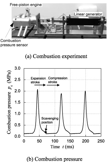
Combustion characteristics.
The output is maximized by operating the braking thrust so as to achieve higher generator efficiency. Figure 12(a) shows the efficiency trend of a typical generator. When generating electricity, it is necessary to operate inside the characteristic line. The generation loss is the sum of the copper loss and the iron loss. The copper loss tends to increase when a large braking force is applied, and the iron loss is likely to increase during high-speed action of the piston. A highly efficient generation area exists at an intermediate position as shown in Fig. 12(a). The efficiency map of the generator discussed in Section 3 also has a high-efficiency area of over 97%. A large braking thrust as shown by line (i) in Fig. 12(a) leads to inefficient generation and low output. Therefore, improved output is expected by setting the braking thrust in a high-efficiency area as shown by line (ii) in Fig. 12(a), which is defined as a maximizing generation output (MGO) operation. This leads to increased high-efficiency generation and extends the stroke after the scavenging point, as shown in Fig. 12(b). Extending the stroke increases the friction loss of the piston. However, it has been reported that the friction loss occurs mainly near the combustion point and that the friction after the scavenging point is small compared to the generation output [9]. Therefore, the MGO is effective for an improved output.
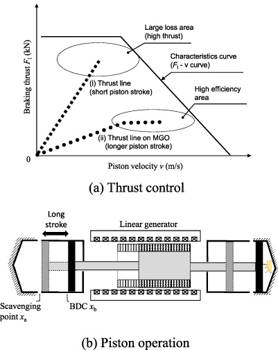
Maximizing generation output operation.
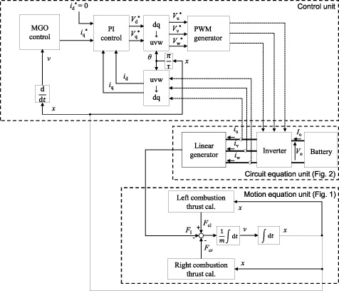
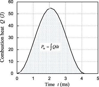
Figure 13 shows a block diagram of the FPEG simulation. The simulator is constructed by combining the motion equation, circuit equation, and vector control unit described in Section 2 with MATLAB-Simulink. The combustion thrust is given by multiplying the bore area A
c
and the combustion pressure p
c
, as expressed by Eq. (8). The combustion chamber pressure is given simply by Eq. (9) based on the adiabatic process [15]. The combustion heat Q of the engine continues for several milliseconds from the combustion start point and is added as a pressure-increasing term dp associated with the combustion heat generation as expressed Eq. (10). Q is given by the Wiebe-function model [21] as shown in Fig. 14. The combustion chamber pressure is released to atmospheric pressure p
a
at the scavenging point. This enables us to simulate the combustion cycle of the two-stroke engine. We use the result of Section 3 for the generator constant. As just explained, we have
Block diagram for FPEG simulation.
Wiebe function for combustion heat.
The ideal braking thrust is 1800 N for the DS-OPM and 1500 N for the DS-SPM, considering the high-efficiency region as shown in Fig. 10. Figure 15 shows the simulation results for the DS-OPM. The time dependence of the combustion thrust is shown in Fig. 15(a). The combustion thrust and piston position characteristics are shown in Fig. 15(b). As with the Otto-cycle of a two-stroke engine [22], the combustion thrust on both sides is well simulated in a state close to an impulse-like feature as shown in Fig. 11(b). The generator input calculated using Eq. ((5)) was 13.7 kW. Figure 15(c) shows the piston action. In the DS-OPM, the stroke operated within the 150 mm movable range of the mover. Figure 15(d) and (e) show the time dependency and the speed dependency, respectively, of the generation braking thrust. The braking thrust resembles a square wave and acts almost in a high-efficiency area. Figure 15(f) shows the generation output, which is the product of the battery current I o and voltage V o . Negative denotes power generation and positive denotes power running that consumes battery power. A generation mode continues without motoring mode (power running mode). The average power was 13.41 kW.
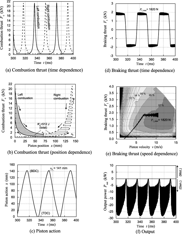
Simulation results.
Meanwhile, we seek to improve the output in the vicinity of 1500 N, which is a high-efficiency region of the DS-SPM as shown in Fig. 10(b). From the simulation, the piston stroke was 171 mm with this braking thrust, which exceeds the 150 mm movable range of the mover. Measures to counteract this are (i) extend the stator length or (ii) apply a large braking thrust. The former method is not desirable for improving the power density because it increases the generator volume and armature resistance. Therefore, we require a braking thrust of around 1800 N so that the DS-SPM achieves a 141 mm stroke as with the DS-OPM. However, a large braking thrust increases the generation time at low-efficiency points, and an output drop is foreseen.
The output-maximizing operation applies a braking thrust in a high-efficiency area. However, the piston stroke exceeded the movable range as in the DS-SPM. The stroke is obtained easily by using the energy conservation law of Eq. (11). In that equation, the effective combustion energy as shown in Fig. 15(b) is converted into the work that is applied to the piston with the braking thrust, i.e., the generator input during one stroke. Because the mover is accelerated instantaneously by the combustion thrust like an impulse, the mover operates almost in the high-speed region of Fig. 10(b), and the braking thrust can be calculated as a substantially constant value in the MGO control. The generator input is 256 J for each combustion. The braking thrust is 1.82 kN considering the high-efficiency area in the DS-OPM. The stroke is 141 mm using Eq. (11). This piston stroke corresponds to the simulation result as shown in Fig. 15(c). In addition, when the braking thrust is 1500 N, the stroke is calculated to be 172 mm in the DS-SPM, which is nearly consistent with the simulation. The piston-stroke prediction of MGO control can be simplified by using the energy conservation law in the FPEG. This method will easily confirm the applicability of the designed generator for high efficiency. As just explained, we have
The power densities under the two conditions are compared in Table 2. The output of the DS-OPM is 0.2 kW larger than that of the DS-SPM, and the power density is improved. The DS-OPM can generate electricity in a high-efficiency area, but the DS-SPM cannot generate inside of its area. Expanding the high-efficiency region along with improving the thrust constant is effective for a larger output within the limited stroke in the FPEG. The DS-OPM is effective for improving the power density.
Comparison of two conditions
The DS-OPM was proposed to improve the power density in consideration of mounting in a car. The back yoke was reduced by sandwiching the permanent magnet of the mover with the armature for miniaturization. The same poles of the permanent magnets were made to face each other, and electromagnetic steel plates were provided between the permanent magnets to improve the thrust constant. The gap magnetic flux density increased from 0.9 T to around 1.1 T, and the thrust constant improved by around 30% compared with that for the same size of DS-SPM. The high-efficiency region expanded and shifted to higher thrust on the efficiency map. In addition, the power-generation state of the dual-type engine was simulated to confirm the improvement effect of the power density of the DS-OPM. The generation efficiency of the FPEG tends to decrease because the combustion energy is input directly to the generator. The output is maximized by controlling the braking thrust to operate at higher efficiency. The stroke could be within the movable range of the mover in the DS-OPM. However, the action range was exceeded because the higher-efficiency braking thrust was lower in the DS-SPM. Because a large thrust is required, the efficiency drops within the movable range. The output densities of the DS-SPM and DS-OPM were 3.57 kW/m2 and 3.62 kW/m2, respectively. The DS-OPM was suitable for improving the output density of the FPEG by expanding the high-efficiency area.
Footnotes
Acknowledgements
This work was supported by JSPS KAKENHI Grant Number 20K14714. This work was partially supported by Nagamori Foundation research grant.