
Abstract
Based on a closed-circuit testing equipment, eddy current loss measurement method of the permanent magnetic material is proposed and studied in this paper. The tested material sample is NdFeB, which has been widely used in electrical machines. The NdFeB is usually coated with corrosion-resistant metal, such as highly conductive zinc and copper to resist corrosion in practical use. The coating material may influence the eddy current loss of the permanent magnet. In this situation, eddy current losses of the NdFeB sample with and without coating are measured and compared with sinusoidal excitation at different frequencies. The experimental results provide very important reference in electrical machine design.
Introduction
Permanent magnetic materials have been widely used in rotating electrical machines. Eddy current loss induced by the fundamental air-gap field is usually neglected in machine design, since it rotates in synchronism with the rotor [1]. To improve the torque density and decrease the torque ripple, novel PM machines are developed rapidly. In which, the stator coils are wound around consecutive or alternate teeth with a fraction number of tooth per pole [2]. The large number of harmonics caused by slot ripple and inversion will lead to eddy current loss in the magnets [3]. Therefore, temperature increasing is caused [4]. In general, the rotor eddy current loss is relatively small compared with the stator copper and iron losses. Nevertheless, it may cause significant heating of the permanent magnet, due to the relatively poor heat dissipation from the rotor, and result in partial irreversible demagnetization, particularly of sintered NdFeB magnets, which have relatively high temperature coefficients of remanence and coercivity and a moderately high electrical conductivity [4]. As a result, it is necessary and important to study the eddy current loss of the permanent magnets.
To investigate the characteristics of the eddy current losses of the permanent magnetic materials, some analytical models and FEA methods were developed [6–8]. Those models or methods often idealize certain conditions, such as ignoring the edge effects of the rectangle shape of the magnets which is mostly used in electrical machines and may lead to a certain amount of errors. The FEA methods remains relatively time-consuming and require to apply fine discretization to accurately model the skin effect, which, in turn, may give rise to numerical instability problems, since the induced eddy currents can be highly inhomogeneous distributed [5]. Also, no matter the analytical model or the FEA method, they both ignore the influence of the coating layer. If that so, the eddy current loss is rather difficult to calculate in both methods. However, the coating layer would somehow contribute to the eddy current loss. An eddy current loss calculation method for the toroid permanent magnetic material sample is proposed in [10]. Due to the magnetic field distribution on each cross section of the toroid sample is the same, the calculation formula can be derived based on the aspect ratio of the cross section.
However, for the cubic sample, magnetic field distribution on each cross section is different, and the eddy current distribution in the cross section is not regular. Therefore, the previous method may not suitable for the cubic sample.
In this paper, the eddy current loss of NdFeB sintered magnetic material is measured by using a newly developed closed-circuit testing equipment, which can imitate the magnetic field in the air gap of the electric machine. By using this method, eddy current losses of NdFeB with both coated and uncoated materials are analyzed and compared. Compared with the analytical or FEA methods, this study can provide rather real loss data. In addition, This measurement can be controlled at different frequencies up to 10 kHz.
Measurement system setup
Excitation structure
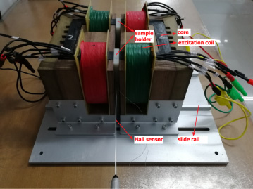
Figure 1 shows the novel dynamic hysteresis loop tester of permanent magnetic material with the frequency up to 10 kHz. The alternating flux density inside the magnet material is up to 0.2 T, which is large enough for the rotor of various AC machines.
The closed-loop magnetic circuit is composed of the double C-shaped cores, flexible excitation windings and the permanent magnetic material sample. The excitation C-shaped cores are made of ultra-thin (0.1 mm) silicon steels, which can run up to 10 kHz. The permanent magnetic sample is made into the cubic-shape, which is located in the air-gap between the double C-shaped cores. And the air-gap between the magnetic poles can be adjusted according to the length of the sample, for the C-shapes is placed on the slide rail.
The four multi-layer excitation windings are separately wound on the C-shaped cores. And the windings are twisted by 12-turns Litz wire, which can guarantee high frequency working. The power amplifier for the excitation windings is PA500 made by Brockhause Company with the frequency from DC to 20 kHz.
Sensing structure
The magnetic flux density sensing coil (B coil) is directly wound around the sample. The number of turns is 14 and the size is same with the cross-section of the sample.
As shown in Fig. 2, there are two samples between one air-gap. The area between the two samples is close enough so that it creates relatively uniform magnetic field, which is measured by the Hall-probe of Bell Gauss meter 8030.
The setup of measurement system.

The structure of NdFeB sample and the B sensing coils.
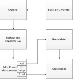
Block diagram of the experimental setup.
The uniformity of the magnetic field distribution between the two cores is a key factor to guarantee the measurement accuracy. Therefore, it is necessary to validate the magnetic field distribution before the experiment. The air gap between the cores and the installation position of the samples are shown in Fig. 4.
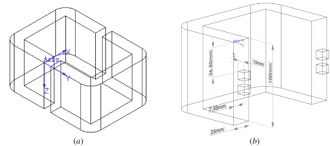
(a) The air gap between the cores, (b) The installation position of the samples.
The magnetic flux density distributions in the air gap along x, y and z directions are measured with a Hall sensor under 1 kHz excitation. As illustrated in Fig. 5, the results show that the magnetic flux density distributions are uniform at the position where the samples are installed.
In the measurement system, the eddy current loss and its dynamic B-H loop of the permanent magnetic materials can be directly measured.
Principle of the measurement
Under the alternating current by the flexible excitation winding, the magnetic field inside the permanent magnetic material is alternatively changing at the static working point of static demagnetization curve. The eddy current loss of the permanent magnetic material is calculated in terms of the B-H loop area, which is formed by the magnetic field strength H on the sample surface and the average magnetic flux density B
av
inside the sample. Generally, the calculated total loss is composed of hysteresis loss, eddy current loss, and a small amount of abnormal loss. For NdFeB, the relative magnetic permeability is close to 1 before the knee point in the demagnetization curve. In this range, it can be regarded as no hysteresis loss and abnormal loss. Then the area of the B-H curve measured at this time is equal to eddy current loss. So, the eddy current loss can be calculated as:
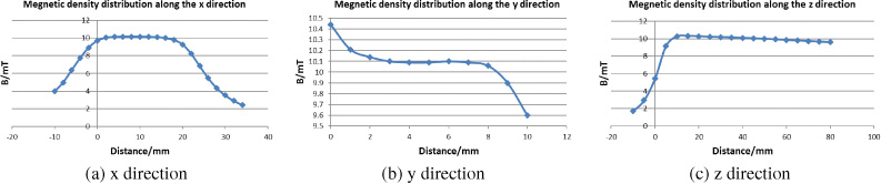
The magnetic density field distributions along x, y and z direction.
B
av
can be calculated by integrating the voltage of the B coil, which is tightly wound around the surface of the samples, seen in Fig. 2, as,
This method of measuring eddy current losses is based on ignoring hysteresis losses. In order to verify the feasibility of this testing method, a copper sample, whose relative permeability is 0.99999, is measured for pure eddy current loss without considering hysteresis loss. Meanwhile, the conductivity of copper is far more than that of NdFeB. Therefore, the experimental results should be more apparent. The eddy current loss of this copper sample is measured at different frequencies and different magnetizations.
The dimensions of the coper sample is 10 ∗10 ∗10 mm. The induced voltage of the B coil and the voltage signal of the Hall sensor should have the same phase when the sample is outside of the B coil, as shown in the Fig. 6.a When a copper sample is placed in the B coil, it can be clearly seen that the induction voltage lags the voltage signal of the Hall sensor and the phase deviation is 0.3140/rad at 1 kHz, as shown in the Fig. 6.b The phase deviation increases with the growth of the exciting frequency, and it reflects the eddy current effect of the copper. The phase shift at different frequencies is shown in Table 1.
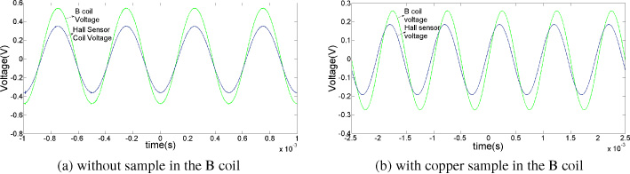
Voltage signal of the B coil and Hall sensor under 1 kHz.
Phase shift of copper sample at different frequencies
Figure 7.a shows the B-H curves at different average magnetic flux densities, ranging from 1 mT to 30 mT and the excitation frequency is 1 kHz. Figure 7.b shows the B-H curves at different frequencies, ranging from 100 Hz to 3 kHz, when the B av is 30 mT. The B-H curves shown in the figure are almost regular elliptic shape, which is obviously different from those with hysteresis.
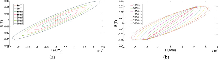
(a) f = 1 kHz, B-H loop at different average magnetic density B av , (b) B av = 30 mT, B-H loop at different exciting frequencies.
The corresponding loss values are shown in Fig. 8.
In permanent magnet motors, the eddy currents generated by the permanent magnets are mainly due to high-order non-synchronous time and space harmonics. In addition, NdFeB needs to be protected in practical applications, the outer surface of the magnet is often electroplated with zinc or copper. The losses of NdFeB sample (10 ∗10 ∗10 mm) with and without coating at different frequencies are tested and compared in this paper.
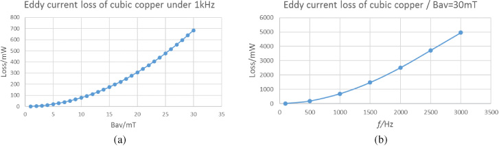
(a) f = 1 kHz, Eddy current losses at different B av , (b) B av = 30 mT, Eddy current losses at different exciting frequencies.
Figure 9.a shows the B-H curves when the B av is 5 mT and 20 mT and the excitation frequency is 1 kHz. Figure 9.b shows the B-H curves when the frequency is 500 Hz and 3000 Hz, and the B av is 30 mT. The B-H loops shown in Fig. 9 are also elliptic, same as that of the copper sample, but much narrower because of the much lower conductivity, and this phenomenon validates the feasibility of the measurement method. Fig. 9.c shows that the eddy current loss changes with B av under different frequencies. (d) shows that the eddy current loss changes with f under different magnetic flux density.
The skin depth of the NdFeB within 3 kHz is shown in the Table 2. It shows that the skin depth is greater than the side length (10 mm) of the cubic sample. As a result, the change of eddy current loss with frequency is more regular compared with copper, for it ignoring the skin effect; furthermore, the estimated calculation formula can be fitted from the experiment loss values at different magnetic flux densities and different frequencies. Polynomial fitting is performed on P and B
av
at different frequencies,
Figure 10 shows the eddy current loss P changes with f and B av .
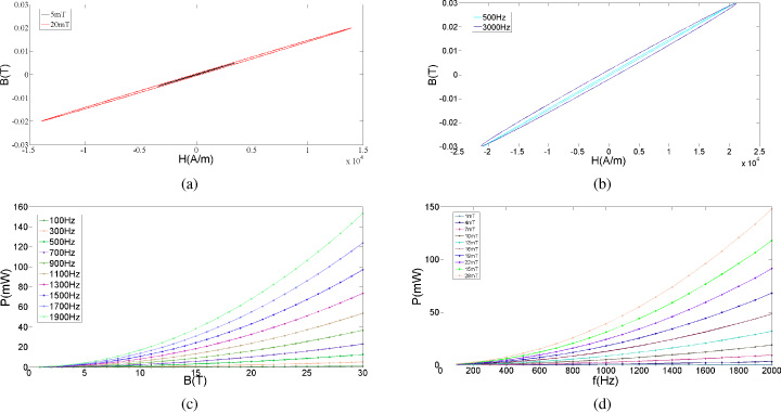
(a) B-H curves when B av = 5 mT, 20 mT, f = 1 kHz. (b) B-H curves when f = 500 Hz, 3000 Hz, B av = 30 mT. (c) The eddy current loss changes with B av under different frequencies. (d) The eddy current loss changes with f under different magnetic field density.
Skin depth of NdFeB at different frequencies
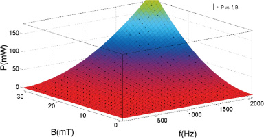
The eddy current loss P changes with f and B av .
For coated samples, the eddy current loss is different from that of the uncoated because the electrical conductivity of the coating layer is higher than that of NdFeB by two orders of magnitude. The conductivity of NdFeB, zinc, copper is shown in Table 3.
Conductivity of copper, zinc and NdFeB
Conductivity of copper, zinc and NdFeB
The eddy current losses of NdFeB with and without coating is shown in the Fig. 11, when the applied magnetic field strength H = 30 kA/m. It shows that the eddy current loss of NdFeB with zinc coating is slightly more than that of the uncoated, and the difference value is rather small in the frequency range 100 Hz–3 kHz. However, the sample coated with copper has much more eddy current loss compared with that of the uncoated sample. Meanwhile, the larger the frequency is, the more obvious the difference value is. The percentage of loss growth can be obtained from the following equation:
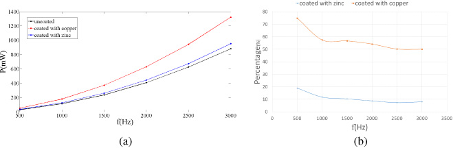
(a) comparison of eddy current loss of galvanized and uncoated NdFeB, (b) The growth ratio of eddy current loss when the NdFeB magnet are coated with zinc and copper respectively.
The growth ratio of the eddy current loss is stable, and this result can be useful for all of the existing methods, no matter analytical or finite element method, which usually ignore the coating effect, that is, increasing the calculation result by 10.87% and 57.26% of zinc-coated and copper-coated NdFeB respectively. As a result, the coating materials bring two influences to the eddy current loss. On one hand, the coating material itself generates eddy current loss, which will have a relatively high quantity due to its high conductivity. On the other hand, the opposite magnetic field generated by the eddy current of the coating material can weaken the exciting magnetic field and therefore reduce the eddy current loss of NdFeB. The experimental results show that the quantity of loss increasing produced by the coating layer is more than the quantity of loss decreasing in the magnets.
In this paper, a novel eddy current loss tester of permanent magnetic material is designed and analyzed. For the NdFeB material, neglecting the hysteresis loss, the area of B-H loop represents eddy current loss and a estimation equation is put forward. The eddy current loss may increase about 10.87% and 57.26% of zinc-coated and copper-coated NdFeB respectively, which should be considered when calculating the eddy current loss with analytical method or FEA method. The measurement results provide important reference for the eddy current loss modeling of permanent magnetic materials at different frequencies.
Footnotes
Acknowledgements
This work was supported in part by the National Key R & D Program of China (2017YFB0903904), the National Natural Science Foundation of China, (No. 51777055, 51690181), Hebei Province Science Foundation for Distinguished Young Scholars (No. E2018202284), and Program for Hundred Excellent Innovative Talents of Hebei Province (No. SRLC2017031).