



Abstract
The low-speed Maglev train adopts single-sided linear induction motors (SLIMs) as traction part. Although the phase winding normally adopts single-branch in order to avoid circulating current caused by longitudinal end effect, the influence of circulating current is not investigated in detail. This paper calculates the circulating current and force performance of SLIMs with dual-branch by 3D finite element method (FEM). Firstly, two kind connections of dual-branch phase winding are introduced, called continuous connection or interval connection respectively. Secondly, the circulating current and force performance are obtained at both starting and steady state, and then the effect of circulating current on force performance is deduced. Thirdly, the contribution to force performance by each coil assembly is studied. Finally, the circulating current, force performance and efficiency under different air gap length are analyzed. It is demonstrated that the dual-branch connection has better force performance than single-branch one, but also bigger current unbalance and lower efficiency.
Keywords
Introduction
Single-sided linear induction motors (SLIMs) are fully aware of the simple structure without auxiliary middle mechanisms, such as gears or links, which brings the advantages of easy maintenance and low cost. They are applied in many areas, such as low-speed Maglev train and linear metro. In these applications, SLIMs have a short primary fixed to the carriage body and a long compound-secondary installed on the rails [1]. They produce not only the thrust force to drive the train, but also the normal force which affects the levitation system [2–5]. Along with the velocity increasing demand of low-speed Maglev train, it is of great importance to obtain enough thrust force at high velocity. Therefore, many approaches of enhancing the thrust force have been proposed, such as magnet rotator type compensator, ladder slits or squirrel cage secondary, optimized structure and so on [6–9].
The force performance calculation of short primary SLIMs is a vital stage during motor design [10], which has inherent problem of non-continuity of the primary lamination and windings. It causes peculiar characteristics, called longitudinal end effect [11]. The currents of three phase are severe unbalance even supplied with balanced voltage [12]. If the phase winding adopts multiple branches, the circulating current occurs in branches. It makes the phase current become more unbalanced, which has great influence on force performance. Therefore, the phase winding with multiple branches is seldom adopted. The reason is the number of turns per slot is big enough to normal LIMs, which can be easily adjusted as the velocity increases under the limitation of power supply. Nevertheless, it becomes very small in SLIMs for low-speed Maglev train. It can be counted with a hand, so the adjustment becomes not so flexible and the current may have a big variation even with one turn difference. Under the power supply limitation, the phase winding with multiple branches may become an effective method as the maximum velocity of Maglev train increases [13].
In order to improve the maximum operating velocity and slightly affect winding structure, the dual-branch phase winding is suitable. This paper investigates the influences of circulating current under this condition.
SLIM topology and parameters
Figure 1(a) shows the half-sectional view of low-speed Maglev train. As can be seen, the fixed part on the ground is demonstrated with two respective views. The cross-section view is shown on the left part and the outline structure is displayed on the right part. Figure 1(b) shows its side view. In the figure, x-, y- and z-axis represent the motion direction, the levitation direction and the transverse direction, respectively.
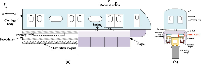
Low-speed Maglev train system. (a) Half-sectional view (cross-sectional view and front view), (b) Side view.
Each SLIM is separated as a primary and a secondary. The primary is fixed to the carriage body and the secondary is installed on the rails. When low-speed maglev train system operates, SLIMs produce thrust force and normal force. The former drives the train, and the latter is counteracted by the levitation magnet [14–17]. Apparently, the normal force of SLIM affects the levitation system.
The SLIMs adopting aluminum cap-type secondary increases the effective component of eddy current on secondary reaction plate. Therefore, it behaves better on force performance than the conventional flat compound secondary, which is related to transverse edge effect. In order to consider the transverse edge effect, this paper adopts 3D finite element models to investigate the characteristics precisely [18]. Figure 2 shows the established 3D FE model of the SLIM with single-branch or dual-branch phase winding in order to investigate the force performance and efficiency. In addition, the structure parameters of the prototype are listed in Table 1.
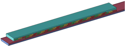
3D FE model of the SLIM with simplified windings and cap-solid secondary.
Structure parameters of the prototype
When three-phase windings are injected with sinusoidal currents, the primary creates a traveling magnetic field wave, which makes the secondary induce eddy current. The traveling magnetic field and induced eddy current interact to generate electromagnetic force, including thrust force F x and normal force F y . The produced thrust force is to drive the magnetic levitation train so it depends on the resistance and required accelerator. To normal force, it is generally opposite to the levitation force produced by levitation electromagnets. That is to say, the levitation force generated by excitation winding is used to balance not only the train weight but also the normal force. Therefore, the normal force should be as low as possible in order to reduce the excitation current [19].
The electromagnetic force per unit area can be obtained by calculation method of surface impedance in multilayer universal model. In this paper, there are primary, mechanical air gap, secondary conductor, secondary iron yoke and air region, five layers in total for typical compound secondary LIMs. The corresponding equations can be expressed as follows.
The arrangement and connection of armature windings are exhibited by the simple structure of one pole pair, as shown in Fig. 3(a). The cap-solid secondary is composed of the aluminum reaction plate on the top and the back iron at the bottom, as shown in Fig. 3(b) [20–22]. For the purpose of minimizing the weight of primary, the material of primary windings is aluminum. In the same time, the reaction plate of the compound secondary is also aluminum considering the cost. The ends of windings are simplified and the segments with the same mark number are connected to be as one coil assembly. For instance, the coil assembly N i under one pole is comprised of N i -1, N i -2, N i -3, N i -4, N i -5 and N i -6 (N = A, B, C; i = 1, 2, 3, 4, 5, 6, 7, 8). All coil assemblies can be connected in series or parallel, so the phase winding can adopt single-branch or multi-branch connection method.

Simplified diagram of winding arrangement. (a) Simple structure of one pole pair. (b) Side view with simplified windings.
As shown in Fig. 3, a coil assembly of this SLIM is composed of six segments when neglecting winding ends. Since the SLIM has eight poles, there are eight coil assemblies and they are marked as number 1 to 8 from the left end to the right end in primary. Normally, the SLIMs in low speed maglev train employ the series one to avoid circulating current. However, the influence of circulating current is seldom focused. As a matter of fact, the design of phase winding can become more flexible if adopting dual-branch connection method.
For phase winding with dual-branch, Fig. 4(a) and (b) show two kinds of connection methods, called continuous connection and interval connection respectively. Continuous connection has four coil assemblies in left constructing one branch, and the other four in right is another branch. To interval connection, the odd number of coil assemblies is one branch and the even number is another branch.
In order to approach the practical situation, the constant voltage source is adopted instead of the constant current source considering the impedance of winding ends. For fair comparison, the number of turns per slot for dual-branch is twice as single-branch. The circuit parameters are listed in Table 2, including the number of turns per slot, resistance and leakage inductance.

Phase winding with dual-branch. (a) Continuous winding circuit. (b) Interval winding circuit.
Circuit parameters of the prototype
Force performance
The force performance including the thrust force and normal force with dual-branch are calculated and compared with those of conventional SLIM with single-branch under the constant voltage supply and the velocity of 160 km/h, as shown in Fig. 5. They are displayed in two electrical cycles under steady state.
To thrust force, the SLIM with dual-branch connection has slightly improved. Apparently, the continuous connection behaves better than the interval one. It has the increase rate of 3.27% and 5.29% compared to the interval connection and conventional single-branch, respectively [23]. To normal force, the variation is more apparent in contrast with the thrust force. Since the normal force needs to be as low as possible in order to reduce the levitation current, the dual-branch with continuous connection is more beneficial, which has decreased 2.82% and 25.41% in comparison with the interval connection and conventional single-branch. The dual-branch with continuous connection has an obvious advantage on both thrust and normal force. Moreover, the normal force has been diminished by nearly a quarter, which is a big progress for the design of SLIMs applied in Maglev train.
In Table 3, the average thrust force and normal force are listed in detail. On viewing the force performance, the dual-branch adopting continuous connection is the best choice under constant voltage supply.
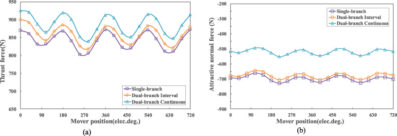
Force performance of SLIM under three connection methods. (a) Thrust force. (b) Normal force.
Average thrust force and normal force of SLIMs with three connection methods
The dual-branch connection brings a problem of circulating current, which means one branch has the increased current and the other one has the decreased current. It influences the induced eddy current on secondary reaction plate, and then acts on force performance. Current waveforms under three connection methods are displayed in Fig. 6. Those with the same basic color belong to the same phase. The dark color curve is phase current and the light color is circulating current. It can be seen that the current curves of three phases are basically balanced with all connection methods. Moreover, the phase current in dual-branch is more than that in single-branch. Therefore, dual-branch improves the phase current. To circulating current, it has the same period with phase current, however, the phase is different. The circulating currents are unbalanced, including the phase and amplitude.
Three phase currents and circulating currents are listed in Table 4. Considering the structure of SLIM, the three phase currents are unbalanced due to unbalanced magnetic circuit and the longitudinal end effect. Dual-branch has bigger phase current due to the decreased impedance compared with single-branch. Apparently, the circulating current of phase A is the biggest, and that of phase B is the lowest. To continuous connection, the circulating current of phase B is higher than that of interval connection, but the circulating current of phase A and C is lower.
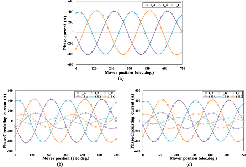
Current waveform under three connection methods. (a) Single-branch. (b) Dual-branch continuous connection. (c) Dual-branch interval connection.
Phase currents and circulating currents under three connection methods
Figure 7 shows the thrust force and normal force of the SLIM with dual-branch continuous connection produced by phase current and winding current. The forces produced by circulating current can be extracted by subtracting them. As can be seen, the force produced by circulating current is negative in comparison with phase current. Nevertheless, the descent effect is much more obvious for the normal force compared with the thrust force. In detail, the thrust force decreases by 2.48%, and the normal force increases by 31.18%. It is a big step for the decrease of levitation current and can save much cost for SLIMs. It can be concluded that the circulating current makes great contribution to the normal force performance although it has a little decrease of thrust force. However, the copper loss is an inevitable problem for dual-branch circuit, and it will be illustrated in the next part.
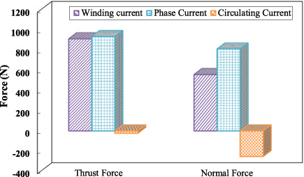
Thrust force and normal force produced by winding, phase and circulating current in dual-branch continuous connection.
The circulating current appears and the phase effective current increases when the phase windings connection changes from single-branch to dual-branch. It can be deduced that the copper loss rises as well. If the dual-branch has better force performance only by increasing the copper loss, it has no application necessity. It is of significance to investigate how force performance will behave when the single-branch and dual-branch circuit generate the same copper loss. To achieve the same copper loss in two cases, the constant voltage supply is reduced for the steady state and the constant current supply is adjusted for the starting state.
Thrust force and normal force with the same copper loss
Thrust force and normal force with the same copper loss
To steady state, the thrust force is reduced by 6.47% and the normal force increases by 34.73% according to Table 5. Consuming the same copper loss, the thrust force and normal force decrease at the same time, but the descent ratios vary widely. Although the thrust force gets a little worse, the normal force is enhanced a lot. Moreover, the normal force changes over quintuple than the descent rate of thrust force.
To starting state, the thrust force and normal force nearly has no difference as a result of the small circulating current in dual-branch. Moreover, the copper loss of circulating current is small under the big constant current supply. Thus, the copper loss has little impact under the starting state.
With the same copper loss, the dual-branch makes the normal force improve a big step with a proper drop on thrust force in steady state and almost has little impact in starting state. This paper studies only one motor, and normally there are ten motors for a train in practical situations. It saves nearly one third of the levitation energy taking no account of the train weight, which will significantly reduce the cost.
Comparing with the single-branch circuit, the influence of circulating current on force performance in dual-branch circuit has been studied. Nevertheless, it has not investigated the contribution of each coil assembly acts on thrust force and normal force. Compared the model having all coil assemblies with the model lacking one coil assembly, the contribution of this coil assembly is achieved, which expressed in percentage. For an instance, if lacking the coil assembly A 1 under single-branch, the thrust force decreases by 3.06% comparison with the full model. Therefore, the contribution of A 1 to thrust force is 3.06%. The radar charts can be obtained in Fig. 8.
Each coil assembly produces the thrust force and normal force because the contributions are all positive. The radar is divided into three phases, and each phase occupies one third of the circle. As imaged, the contribution increases as coil assembly approaches the middle of primary and decreases as it approaches the ends of primary, which arises from longitudinal end effect. Dual-branch makes the contribution of each coil assembly more unbalanced. Therefore, some coil assemblies of dual-branch have higher contribution than those of single-branch, which is defined as contribution increase region. As it can be seen in Fig. 8, the contribution increase regions of thrust force and normal force are different.
To thrust force, the contribution increase region is located in the middle, which is marked under the radar. That is to say, to dual-branch, the thrust force contribution of coil assembly in the middle primary is higher, and those at two ends are small. In the contribution increase region, the thrust force has a slight increase of 5.29%. To normal force, the contribution increase region is located at the right half of the primary. As calculated, the normal force of dual-branch has a decrease of 25.41% comparing with that of single-branch. Therefore, the decrease region has more influence on normal force than the increase region in total.
In conclusion, it achieves the increase trend of thrust force and the decrease trend of normal force in the radar charts with separating the contribution of each coil assembly. Both the coil assembly position and circulating current are the influence factors of contribution.
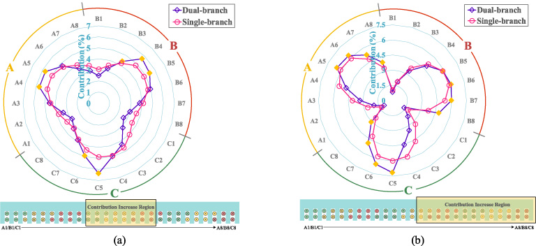
Influence on force performance of each coil assembly and diagram of contribution increase region. (a) Thrust force. (b) Normal force.
Due to the continuity of motor operation process, it is of great significance to study the steady state as well as the starting state. The condition in starting state is set under constant current source with the maximum phase current. As displayed in Fig. 9, the thrust and normal force curves are nearly the same under three phase winding connections ignoring the finite element method (FEM) calculation error.
In order to illustrate the unbalance clearly, the copper loss in continuous and interval dual-branch is shown in Fig. 10. The bars with the same basic color are attributable to one phase. Continuous and interval dual-branch is separated by dark and light color. The copper loss of phase current in continuous circuit is higher in comparison with that in interval circuit under steady state. The current is related to unbalanced structure of SLIM. Phase B is hardly affected by longitudinal end effect, following with phase C and A in steady state, however, the consequence changes to phase C, A and B in starting state.
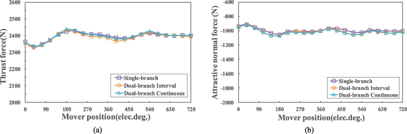
Force performance under starting state. (a) Thrust force. (b) Normal force.

Copper loss of circulating current and phase current under continuous and interval dual-branch connections. (a) Circulating current. (b) Phase current.
It has discussed the force performance in starting state under three winding circuit connections above, then it will investigate the relationship of circulating current and phase current under starting and steady state. Firstly, the copper loss ratio is 2.88%, 0.54% and 1.96% under steady state by comparison to those are all less than 0.07% under starting state. It can be concluded that the circulating current decreases much under starting state than steady state. Moreover, the copper loss of circulating current under starting state can be ignored to some extent when it compares with the steady state as demonstrated. Secondly, the phase current under starting state is higher than that under steady state, whereas, the circulating current is lower. Hence, the distortion between phases is less severe, and it benefits the starting process. Thirdly, it is supposed to place emphasis on dynamic longitudinal end effect under steady state rather than static longitudinal end effect, but it is opposite under starting state. The circulating current results have verified the conclusion with phase C is more balanced under starting state and phase B is more balanced under steady state.
In order to find out how the circulating current affects the force performance under starting state, this paper separates the phase current and circulating current. Due to the low circulating current, the phase current and winding current have little difference. Thus, the forces also vary little. According to Fig. 11, the circulating current only has 0.04% drop and 0.30% increase on thrust force and normal force, respectively. The circulating current in starting state has much lower influence on force performance than that in steady state.
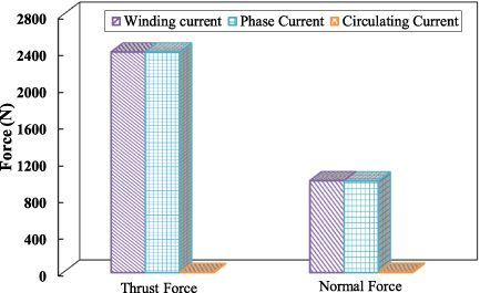
Thrust force and normal force produced by winding current, phase current and circulating current under starting state.
Comparison of circulating current under steady and starting state
When Maglev train operates with the velocity of 160 km/h, the dynamic longitudinal end effect must be taken into consideration. Under steady state, the back electromotive force (EMF) has significant influence on phase current. Beginning from the right end of the primary, the phase sequence is phase A, phase C and phase B. The dynamic longitudinal end effect leads to the decrease of back EMF, so it works to circulating current as well as phase current. The nearest phase to the right end has the most severe longitudinal end effect. As a result, the current of phase B has the lowest circulating current, following with phase C and phase A, which also acts on phase current including the continuous dual-branch and single-branch connections except for the interval connection. The reason is that the interval connection weakens the longitudinal end effect, which makes the current of phase C a little more than the current of phase A. According to Table 6, the average copper loss ratio under starting state is 0.0433% in continuous connection and that under steady state is 1.8497%, while the total ratio is only 0.0234%. As a result, circulating current and its copper loss under starting state are far less than that under steady state, which has lower effect on starting state for SLIMs.
In order to find out how the air gap acts on circulating current, this paper investigates the force performance and efficiency considering circulating current under different air gap lengths. Figure 12 shows the average thrust force and normal force under three phase winding connections, including single-branch, dual-branch continuous and dual-branch interval connection.
The thrust and normal force drop with the increase of air gap length. For better force performance of SLIMs, the thrust force is supposed to be higher and the normal force is supposed to be lower. As a result, the continuous connection method has an apparent advantage among three for all air gap length range.
After considering the force performance, the efficiency matters in motor operation as well. As displayed in Fig. 13, the efficiency has decreasing trend as the air gap length increases for all three connections. Although the continuous connection behaves better on force performance, it has a reduced efficiency of about 2% compared with single-branch. On account of the circulating current in dual-branch, the efficiency is supposed to decrease. In addition, the phase current under continuous circuit increases a lot in comparison to the interval one. However, the increased current is mostly reactive current. In total, the single-branch has the maximum efficiency, following with the interval and continuous connection. In conclusion, the dual-branch continuous connection has better force performance with sacrificing 2% efficiency.

Force performance under three circuit connections according to air gap length from 11 to 15 mm. (a) Thrust force. (b) Normal force.
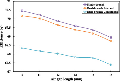
Efficiency under three connection methods with air gap length ranging from 10 mm to 15 mm.
The phase current, circulating current, the copper loss ratio of circulating current to phase current are listed according to air gap length under three different phase winding connections in Table 7 to 9. It agrees with the regular rule that the phase current is boosted with the increase of air gap length due to the reduced impedance. In addition, the circulating current under dual-branch connection has influence on the stability of SLIMs.
If the copper loss is so high that it cannot control within the permitted temperature rise, then it cannot be applied to SLIMs. However, the circulating current decreases as the increase of air gap while the phase current increases. The copper loss ratio is around 3%, 0.5% and 2% impacted by longitudinal end effect for three phases, respectively. Under dual-branch connections, the average copper loss ratio decreases as the air gap length increases.
Phase currents under single-branch connection with different air gap length
Currents and copper loss ratios under dual-branch continuous connection with different air gap length
Currents and copper loss ratios under dual-branch interval connection with different air gap length
The single-branch has lopsided phase current due to the inherent structure of SLIMs. In addition, the circulating current in dual-branch makes the current of one branch increase and that of the other branch decrease. It leads to the more lopsided branch current. Therefore, the distribution of motor heat may be non-uniform compared with single-branch connection, which is a disadvantage of dual-branch connection.
To phase current, the dual-branch raises it and the continuous one has the maximum current. Although the circulating current exists in dual-branch, it will do no harm to the force performance. Moreover, it raises the thrust force and makes the normal force dropped at the same time. Nevertheless, the circulating current increases the extra copper loss other than the phase current. But the copper loss of it to total copper loss is less than 4% and it has no great effect on the whole maglev system.
In this chapter, it has studied the force performance, efficiency and copper loss ratio. When the air gap length increases, the thrust force, normal force, efficiency and copper loss ratio are all reduced. From all three connection methods, the dual-branch continuous circuit has the absolute advantage on force performance for all range of air gap length from 10 to 15 mm. Compared with the single-branch, the copper loss of SLIMs increases and the heat is not evenly distributed due to the circulating current in dual-branch. In conclusion, the continuous connection in dual-branch enhances the force performance with only 2% drop on efficiency.
This paper investigates the SLIMs with dual-branch phase winding connection for low-speed Maglev train by calculating the force performance, efficiency and circulating current based on 3D FEM model under constant voltage supply. Compared with conventional single-branch connection, the conclusions can be drawn as follows.
(1) The dual-branch connection method can raise the thrust force and make the normal force drop at the same time. The continuous dual-branch makes the thrust force increase by 5.29% and the normal force drop by 25.41%, while the values are 1.95% and 2.82% for the interval one under constant voltage supply. The circulating current and phase current are lopsided. The circulating currents for three phases are 54.82 A, 22.1 A, and 44.02 A in continuous circuit, and 55.14 A, 21.57 A, 50.38 A in interval one, respectively.
(2) Under steady state, the ratios of the circulating current copper loss to the total copper loss for three phases in dual-branch are 2.88%, 0.54%, 1.96% for continuous one and 3.13%, 0.56%, 2.64% for interval one. Under starting state, the values are 0.0606%, 0.0646% and 0.0045% in continuous one and 0.2129%, 0.2082%, 0.0203% in interval one. Hence, the continuous dual-branch connection behaves better than the interval one in the copper loss of circulating current.
(3) Considering the same copper loss for single-branch and dual-branch, the thrust force decreases by 6.47% and the normal force improves by 34.73% under steady state. Under starting state, the circulating current weakens thrust force by 0.25% and improves normal force by 0.20%. The normal force is improved at a big step with a proper drop on thrust force.
(4) Each coil assembly contributes to the thrust force and normal force. The contribution of one coil assembly is separated in both single-branch and dual-branch. To thrust force, the contribution increase region lies in the middle of the primary. To normal force, it is in the right half of the primary.
(5) With the increase of air gap length, the thrust force, normal force and efficiency are all reduced. Moreover, the circulating current decreases as the phase effective current increases, which diminishes the copper loss ratio of circulating current to phase current.
The dual-branch connection can promote the force performance by comparison to single-branch with sacrificing 2% efficiency under constant voltage supply for SLIMs. Moreover, the copper losses of circulating current are all within 4%, and the descent ratio of normal force is five times than the increase ratio of thrust force at the same copper loss.
Footnotes
Acknowledgement
This work was supported in part by the Natural Science Foundation of Zhejiang Province (LZ17E070001), and Ningbo Science and technology plan project (2018B10068).