
Abstract
The continuously variable transmission (CVT) clumped system with lots of nonlinear uncertainties operated by the six-phase induction motor (SIM) is lacking in good control performance for using the linear control. In light of good ability of learning for nonlinear uncertainties, the sage dynamic control system using mixed modified recurrent Rogers–Szego polynomials neural network (MMRRSPNN) control and revised grey wolf optimization (RGWO) with two adjusted factors is proposed to acquire better control performance. The MMRRSPNN control and RGWO with two adjusted factors can execute intendant control, modified recurrent Rogers–Szego polynomials neural network (MRRSPNN) control with a fitted learning rule, and repay control with an evaluated rule. In addition, in the light of the Lyapunov stability theorem, the fitted learning rule in the MRRSPNN and the evaluated rule of the repay control are founded. Besides, the RGWO with two adjusted factors yields two changeable learning rates for two weights parameters to find two optimal values and to speed-up convergence of two weights parameters. Experimental results in comparisons with those control systems are demonstrated to confirm that the proposed control system can achieve better control performance.
Keywords
Introduction
A six-phase induction motor (SIM) [1–6] has higher efficiency, higher reliability and lower torque ripple in the same size that is compared to a three-phase aluminum induction motor. In addition, the SIM has been used in many industrial and commercial applications [7–13]. In addition, the continuously variable transmission (CVT) clumped system with lots of nonlinear uncertainties operated by the six-phase induction motor (SIM) is lacking in good control performance for using the linear control. Thus, the main motivation is to improve the control performances by using the sage dynamic control method.
Artificial neural networks (NNs) [14–17] have good approximation performance in control and identification of system. But it is very time consuming on online training procedure. Hence, many functional-type NNs [18–20] have been used in control and identification for much nonlinear system as a result of less computational complexity. However, the adjustment mechanics of weights were not discussed in these control methods that combined with NNs. It is leads to larger error in control and identification for system. Besides, the Rogers–Szego polynomials are a family of polynomials orthogonal on the unit circle introduced by Szego [21], who was inspired by the continuous q-Hermite polynomials studied by Leonard James Rogers [21]. However, Rogers–Szego polynomials neural network (RSPNN) has never presented in any identification and control of nonlinear system. Although the feedforward RSPNN can approximate nonlinear function, it may not be approximated dynamic act of nonlinear uncertainties as a result of lacking reflect loop.
The Recurrent NNs [17,22–24] were broadly used in modelling of nonlinear system as and control as result of high certification and fine control performance lately. Because of more benefits than the feedforward RSPNN, the modified recurrent Rogers–Szego polynomials neural network (MRRSPNN) control was not proposed yet for the SIM expelled nonlinear CVT clumped system to raise the certification property of nonlinear system and reduce calculation complexity. Although, Lin [1,7,8] put forward the SIM driving CVT system by means of the BMRGPNN control and AABCO. However, these learning rates using some acceleration factors were absent so that the convergent speed of weights regulation is slower. Thus the proposed sage dynamic control system using mixed modified recurrent Rogers–Szego polynomials neural network (MMRRSPNN) control and revised grey wolf optimization (RGWO) with two adjusted factors for electromagnetic torque control of the SIM expelled the CVT clumped system is the novel control method so as to raise the certification property of nonlinear system, to reduce calculation complexity, and to speed-up convergence of weights regulation.
Emary et al. [25] proposed the multi-objective Grey wolf optimization (GWO) to apply in attribute reduction of system. Mosavi et al. [26] proposed a conventional NN training method and the GWO to apply in the sonar dataset category. Khandelwal et al. [27] proposed the modified GWO to track the programming question of transmitting network. Mirjalili et al. [28] proposed the hunting mechanism of GWO to mimic the social behavior. Even though these algorithm have very high competitive and have been used in various kinds of fields [29–31], they have poor exploration capability and suffer from local optima stagnation. So, in order to improve the explorative abilities of GWO and the slower convergence of GWO, a RGWO with two adjusted factors is proposed to regulate two learning rates with two optimal values and to raise convergent speed of weights in this paper. This newly proposed algorithm consists of two modifications: Firstly, it is able to explore new areas in the search space because of diverse positions assigned to the leaders. This helps in increasing the exploration and avoids local optima stagnation problem. Secondly, an opposition-based learning method has been used in the initial half of iterations to provide diversity among the search agents.
The nonlinear dynamics CVT systems [32–35] driven by the SIM systems [36–39] were proposed. However, those neural networks need longer time to process nonlinear systems The proposed sage dynamic control system using the MMRRSPNN control and RGWO with two adjusted factors can execute intendant control, MRRSPNN control with a fitted learning rule, and repay control with an evaluated rule. In the light of the Lyapunov stability, the fitted learning rule for training parameters in the MRRSPNN is derived online. Therefore, the MMRRSPNN can react to nonlinear uncertainty by learning procedure online. Besides, the RGWO with two adjusted factors, which is used to revise two learning rates of connective weights and recurrent weights in the MRRSPNN, is proposed to attain better convergence and to speed-up convergent speed of weights regulation so as to search for two optimal values. Finally, better control performances obtained by the proposed control method are demonstrated and confirmed by the tested results.
The main tissue in this paper is as follows: Section 2 presents the construction of the SIM expelled CVT clumped system. Section 3 presents the sage dynamic control system using MMRRSPNN control and RGWO with two adjusted factors. Section 4 presents the tested results for the SIM expelled CVT clumped system by using three control methods at three tested cases. Section 5 presents the conclusions.
Construction of CVT clumped system and SIM modelling system
Geometric construction of CVT clumped system
The SIM expelled CVT clumped system with nonlinear uncertainties results in seriously variation. Under the CVT clumped system with nonlinear friction, the torque and speed in the SIM expelled CVT clumped system begets retrograde tracking responses under nonlinear uncertainties. The geometric construction of the SIM and CVT clumped system with negligible belt flexural effects, power and sliding losses is illustrates in Fig. 1 [36–39]. The dynamic equations for all torques under simplified kinematics of the CVT clumped system in the succeeding driven shaft and the preceding driving shaft by using the law of conservancy shown in Fig. 1 are simplified as
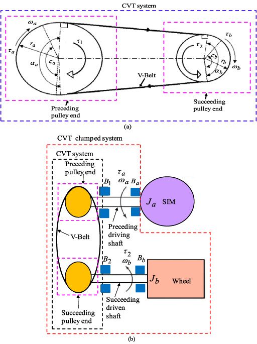
Geometric construction of the CVT clumped system: (a) the CVT system and (b) the SIM and CVT clumped system.
The d
1 − q
1 − d
2 − q
2 axes electric equation in the coordinate frames transformation from the six-phase x
1 − y
1 − z
1 − x
2 − y
2 − z
2 axes to the d
1 − q
1 − d
2 − q
2 axes of the SIM can be represented by [2–6]
Figure 2 displays the construction of the SIM expelled CVT clumped system that is composed of three parts as the SIM expelled system, the CVT clumped system and the mix signal field programmable gate array (FPGA) system and TMS 320F28335 digital signal processor (DSP) control system. The CVT clumped system consists of the wheel and the CVT system. The SIM expelled system consists of the current sensors and A/D converter, the sinusoidal pulse width modulation (PWM) control circuit, the interlock and isolated circuits, and the voltage source inverter with six sets of insulated-gate bipolar transistor (IGBT) power modules. The mix FPGA system and TMS 320F28335 DSP control system manufactured by Microcontroller Company can execute an IFOC, a proportional-integral (PI) current control loop and a speed control loop. The IFOC consists of the sin θ e ∕cos θ e generation, the lookup table generation and the coordinate translation. Two gains of the PI current controller are k p1 = 18.1 and k i1 = k p1∕T i1 = 7.2 via certain heuristic comprehension [40–42] in order to get good dynamic response. The SIM expelled system was controlled by the TMS 320F28335 DSP and the mix FPGA control system under aggregated parameter variations and aggregated nonlinear outward disturbances.
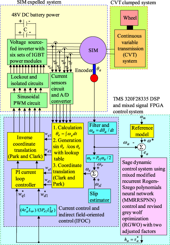
Construction of the SIM expelled CVT clumped system.
For simplifying the sage dynamic control system design, the entire dynamic equation from ((5)) can be represented by
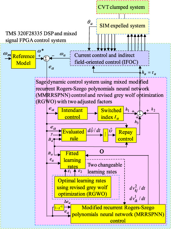
Block diagram of the sage dynamic control system using MMRRSPNN control and RGWO with two adjusted factors.
From Eq. (14) to Eq. (18), a discrepancy dynamic equation can be represented by
Furthermore, the MRRSPNN with three-layer conformation that is composed of a first layer, a second layer and a third layer is displayed in Fig. 4. The semaphore intentions in each node for each layer are explained in the following expression.
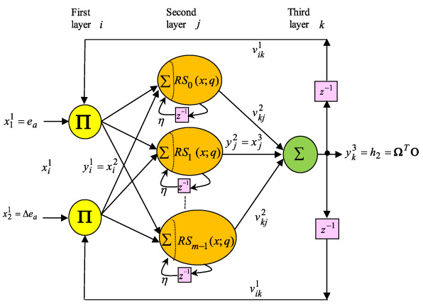
Conformation of the MRRSPNN.
At the first layer, input semaphore and output semaphore are explained by
At the second layer, input semaphore and output semaphore are explained by
At the third layer, semaphore and output semaphore are explained by

Flowchart of of realized control methodologies with real-time implementation by using the DSP control system.
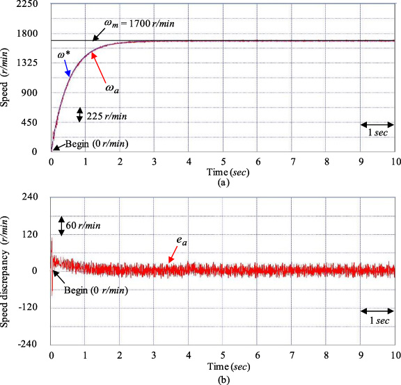
Tested results for the SIM expelled CVT clumped system at the tested Example D1 case by using the controller XT1: (a) speed response, (b) speed discrepancy response.

Tested results for the SIM expelled CVT clumped system at the tested Example D2 case by using the controller XT1: (a) speed response, (b) speed discrepancy response.

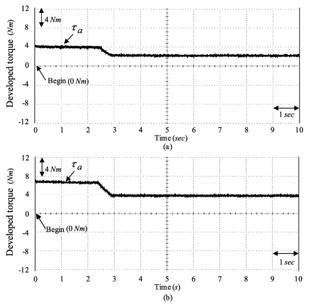
Tested results for the SIM expelled CVT clumped system by using the controller XT1: (a) response of developed torque at the tested Example D1 case, (b) response of developed torque at the tested Example D2 case.

Tested results for the SIM expelled CVT clumped system at the tested Example D1 case by using the controller XT2: (a) speed response, (b) speed discrepancy response.

Tested results for the SIM expelled CVT clumped system at the tested Example D2 case by using the controller XT2: (a) speed response, and (b) speed discrepancy response.
Tested results for the SIM expelled CVT clumped system by using the controller XT2: (a) response of developed torque at the tested Example D1 case, (b) response of developed torque at the tested Example D2 case.
Moreover, a minimum discrepancy 𝜌 so as to execute the repay control can be represented by
A training means of parameters in the MRRSPNN can be unearthed by use of Lyapunov stability and the gradient descent skill. The RGWO with two adjusted factors is applied to look for two better learning rates in the MRRSPNN to acquire faster convergence The connective weight presented in Eq. (29) can be represented by
In the RGWO, the optimization is conducted by 𝛼, 𝛽 and δ. The RGWO algorithm can be denoted by
The construction of the SIM expelled CVT clumped system by use of TMS320F28335 DSP and mixed signal FPGA control system is shown in Fig. 2. The rated constitution of the CVT clumped system are below as 646.6 mm for V-belt length, 72.4 mm for preceding pulley diameter, 31.3 mm for succeeding pulley diameter, 4.2 for conversion ratio. The rated format of the SIM is given as six-phase 48 V, 2 kW, 3476 r/min. The electrical and mechanical parameters of the SIM are given as r s = 2.86 Ω, L ss = 19.16 mH, L rr = 19.14 mH, k ar = 0.216 Nm/A, J a = 19.12 × 10⁻³ Nms, B a = 3.28 × 10⁻³ Nms/rad. Because of inherent uncertainty in the CVT clumped system e.g., the aggregated parameter variations and the aggregated nonlinear outward disturbances and current output limitation for DC power source, the SIM only expelled at 3400 r/min for avoiding burn down IGBT power modules for the CVT clumped system. The flow chart of realized control methodologies with real-time implementation by using the TMS320F28335 DSP and mixed signal FPGA control system via the “C” language in the experimental tests incorporates the leading program (LP) and the sub-leading interrupt service routine (SLISR) which is illustrated in Fig. 5.
Tested results for the SIM expelled CVT clumped system obtained at the tested Example D1 case by using the controller XT3: (a) speed response, (b) speed discrepancy response.

Tested results for the SIM expelled CVT clumped system at the tested Example D2 case by using the controller XT3: (a) speed response, (b) speed discrepancy response.

Tested results for the SIM expelled CVT clumped system by using the controller XT3: (a) response of developed torque at the tested Example D1 case, (b) response of developed torque at the tested Example D2 case.
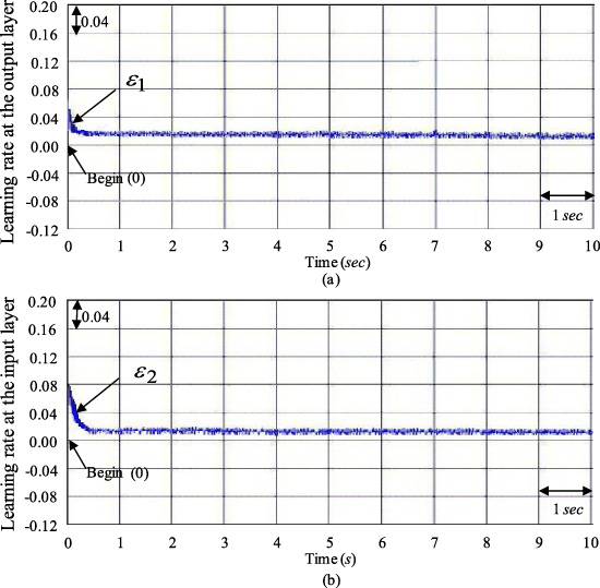
Tested results at the tested Example D1 case by using the controller XT3: (a) convergent response of learning rate ϵ1, (b) convergent response of learning rate ϵ2.

Tested results at the tested Example D2 case by using the controller XT3: (a) the convergent response of learning rate ϵ1, (b) the convergent response of learning rate ϵ2.

Tested results at the tested Example D3 case by using the controller XT1: (a) speed-adjusted response; (b) current response in phase a1.
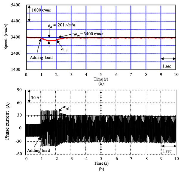
Tested results at the tested Example D3 case by using the controller XT2: (a) speed-adjusted response; (b) current response in phase a1.
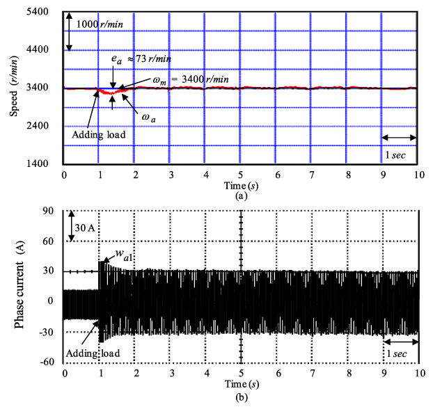
Tested results at the tested Example D3 case by using the controller XT3: (a) speed-adjusted response; (b) current response in phase a1.
All input/output (I/O) initialization and parameters are first processed in the LP and then the interrupt time in the SLISR is set. The SLISR with 2 msec sampling time is applied for reading six-phase currents from A/D converters and rotor position of the SIM expelled CVT clumped system from encoder, calculating rotor position and speed, executing lookup table and coordinate translation, executing PI current control, executing the proposed control system, and outputting six-phase sinusoidal PWM signals to drive the IGBT power module voltage source inverter. Two judger g1 and g1_mx shown in flowchart are provided to realize the IFOC by mixed signal FPGA system The judger g2 is provided to realize the proposed control scheme by TMS320F28335 DSP control system Two initial values g1 and g2 are set zero. The initial value g1_mx is set three. When the IFOC realized by mixed signal FPGA system is implemented less three times, i.e., g1 < g1_mx, the IFOC must be continuously realized by mixed signal FPGA system Then this process will go back the primary start. Therefore, the IFOC realized by mixed signal FPGA system will execute three times, then the proposed control scheme realized by TMS320F28335 DSP control system will executes one time.
Some experimental results with two tests are demonstrated to show various control performance. The one aggregated parameter variations and aggregated nonlinear outward disturbances Δτ c1 + τ u1 case at 1700 r/min is the tested Example D1 case. The double aggregated parameter variations and aggregated nonlinear outward disturbances 2Δτ c1 + τ u1 case at 3400 r/min is the tested Example D2 case. Besides, for comparison control performance by using the celebrated PI controller as the controller XT1, the MRRHPNN control system with mend ACO [1] as the controller XT2 and the proposed sage dynamic control system using MMRRSPNN control and RGWO with two adjusted factors as the controller XT3 are adopted in this paper.
To get good transient-state and steady-state control performance, two gains of the celebrated PI controller as the controller XT1 are k p2 = 18.2, k i2 = k p2∕T i2 = 4.2 by use of the Kronecker method to build a stability boundary in the k p2 and k i2 plane [40–42]. This method is used to narrow down the region for iterative selection of values of the parameters of k p2 and k i2 [40–42] on the tuning of the PI controller with one aggregated parameter variations and aggregated nonlinear outward disturbances Δτ c1 + τ u1 case at 1700 r/min for the speed tracking.
The MRRHPNN control system with mend ACO [1] as the controller XT2 adopted 2, 3 and 1 nodes in the first, second and third layers, respectively. Moreover, all gains are set to achieve better transient control performance in tests considering the requirement of stability. Besides, two gains of the MRRHPNN control system with mend ACO [1] are given by k a = 3.5, 𝜂 = 0.11, 𝛾 = 0.22.
The proposed sage dynamic control system using MMRRSPNN control and RGWO with two adjusted factors as the controller XT3 adopted 2, 3 and 1 nodes in the first, second and third layers, respectively. Besides, all gains are set to achieve better transient control performance in experimentation considering the requirement of stability. Furthermore, two gains of the sage dynamic control system using MMRRSPNN control and RGWO with two adjusted factors are given by k a = 3.5, 𝜂 = 0.11, 𝛾 = 0.22.
Firstly, the tested results for the SIM expelled CVT clumped system by using the celebrated PI controller as the controller XT1 at the tested Example D1 case and at the tested Example D2 case are demonstrated in Figs 6, 7 and 8. Figures 6(a) and 7(a) demonstrate the speed responses in the command speed ω m , reference model speed ω∗, and measured speed ω a . Figures 6(b) and 7(b) demonstrate the speed discrepancy e a responses. Figures 8(a) and 8(b) demonstrate the developed torque τ a responses. Good speed tracking performance at the tested Example D1 case shown in Fig. 6(a) is due to small disturbances which is the same as the rated case. Besides, the developed torque τ a response shown in Figs 8(a) and 8(b) guides to large torque ripple due to the CVT system’s push–pull friction. The tested results show that tardy speed responses demonstrated in Fig. 7(a) was obtained by using the controller XT1 due to unfit gains tuning.
Secondly, the tested results of the MRRHPNN control system with mend ACO [1] as the controller XT2 for the SIM expelled CVT clumped system at the tested Example D1 case and at the tested Example D2 case are demonstrated in Figs 9, 10 and 11.
Figures 9(a) and 10(a) demonstrate the speed responses of measured speed ω a , reference model speed ω∗ and command speed ω m . Figures 9(b) and 10(b) demonstrate the speed discrepancy e a responses. Figures 11(a) and 11(b) demonstrate the responses of developed torque τ a . Figure 9(a) demonstrates good performance of speed tracking at the tested Example D1 case because small disturbance is the same as the rated case. Good speed response is demonstrated in Fig. 10(a) at the tested Example D2 case. The tested results demonstrate that good tracking performance was achieved for the SIM expelled CVT clumped system by use of the controller XT2 due to the online changeable method of the MRRHPNN control system and the compensated controller action.
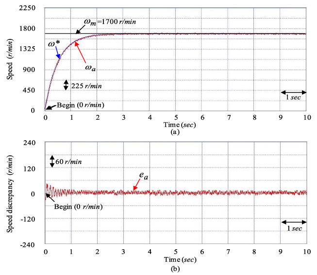
Thirdly, the tested results of the sage dynamic control system using MMRRSPNN control and RGWO with two adjusted factors as the controller XT3 for the SIM expelled CVT clumped system at the tested Example D1 case and at the tested Example D2 case are demonstrated in Figs 12, 13 and 14.
Figures 12(a) and 13(a) demonstrate the speed responses of measured speed ω a , reference model speed ω∗, and command speed ω m . Figures 12(b) and 13(b) demonstrate the speed discrepancy e a responses. Figures 14(a) and 14(b) demonstrate the responses of developed torque τ a . Figure 12(a) demonstrates better performance of speed tracking at the tested Example D1 case because of the same as the nominal case with smallest disturbances. The higher speed tracking response is demonstrated in Fig. 13(a) at the tested Example D2 case. The tested results show that more accurate tracking performance was achieved for the SIM expelled CVT clumped system when the controller XT3 was used because of the online fitted mechanism of the MRRSPNN and the repay controller action. The responses of developed torque τ a shown in Figs 14(a) and 14(b) demonstrate lower torque ripple because of online adjustment of the MRRSPNN control system and RGWO with two adjusted factors to process the unmodelled dynamic of CVT clumped system such as push–pull frictions.
Besides, Fig. 15(a) and Fig. 15(b) demonstrate the convergent speeds of two learning rates ϵ1 and ϵ2 in the MRRSPNN using RGWO with two adjusted factors at the tested Example D1 case, respectively. Figure 16(a) and Fig. 16(b) demonstrate the convergent speeds of two learning rates ϵ1 and ϵ2 in the MRRSPNN using RGWO with two adjusted factors at the tested Example D2 case, respectively.
Finally, the rotor speed response under adding load torque disturbance and aggregated nonlinear outward disturbances 2 Nm (τ t ) + τ u1 at 3400 r/min speed as the tested Example D3 case is tested by utilizing the controller XT1, the controller XT2 and the controller XT3. Figure 17, Fig. 18 and Fig. 19 demonstrate the tested results of speed and current w a1 in phase a1 at the tested Example D3 case when the controller XT1, the controller XT2 and the controller XT3 were used, respectively. Figure 17(a), Fig. 18(a) and Fig. 19(a) demonstrate the speed-adjusted response of the command speed ω m and the measured speed ω a at the tested Example D3 case when the controller XT1, the controller XT2 and the controller XT3 were used, respectively. Figure 17(b), Fig. 18(b) and Fig. 19(b) demonstrate the measured current w a1 in phase a1 at the tested Example D3 case when the controller XT1, the controller XT2 and the controller XT3 were used, respectively. The tested results demonstrate that the degenerated responses at the tested Example D3 case are considerably improved when the controller XT3 was used.
Performance comparisons of control systems
Characteristic performance comparison of control systems
Parameter settings
Main characteristics of three numerical benchmark functions and numerical results obtained by MGWO, GWA with borda coun and RGWO with two adjusted factors

Additionally, Table 1 is listed many performance comparisons of the control systems XT1, XT2 and XT3 with regardine to the experimental results of three tested Example cases. The maximum errors of e a obtained by the control systems XT1, XT2 and XT3 at the tested Example D1 case are the 86 r/min, 67 r/min and 38 r/min, respectively. The root-mean-square (RMS) errors of e a obtained by the control systems XT1, XT2 and XT3 at the tested Example D1 case are the 43 r/min, 28 r/min and 18 r/min, respectively The maximum errors of e a obtained by the control systems XT1, XT2 and XT3 at the tested Example D2 case are the 213 r/min, 86 r/min and 69 r/min, respectively. The RMS errors of e a obtained by the control systems XT1, XT2 and XT3 at the tested Example D2 case are the 58 r/min, 30 r/min and 20 r/min, respectively. The maximum errors of e a obtained by the control systems XT1, XT2 and XT3 at the tested Example D3 case are the 398 r/min, 198 r/min and 41 r/min, respectively. The RMS errors of e a obtained by the control systems XT1, XT2 and XT3 at the tested Example D3 case are the 50 r/min, 20 r/min and 16 r/min, respectively. According to the tabulated measurements, the control system XT3 indeed yields the superior control performances.
Furthermore, Table 2 is listed the control characteristic performance comparisons in the control systems XT1, XT2 and XT3 for experimental results. Dynamic responses with rising time obtained by the control systems XT1, XT2 and XT3 at the tested Example D2 case are the 2.8 sec, 2.6 sec and 2.1 sec, respectively. Load regulation capabilities with maximum error obtained by the control systems XT1, XT2 and XT3 at the tested Example D3 case are the 398 r/min, 198 r/min and 69 r/min, respectively. Convergent speeds with settle time obtained by the control systems XT1, XT2 and XT3 at the tested Example D2 case are the 0.5 sec, 0.3 sec and 0.1 sec, respectively. Rejection abilities for parameter disturbance with maximum error obtained by the control systems XT1, XT2 and XT3 at the tested Example D2 case are the 213 r/min, 86 r/min and 41 r/min, respectively. Torque ripples obtained by the control systems XT1, XT2 and XT3 at the tested Example D2 case are the 8% of nominal value, 4% of nominal value and 2% of nominal value, respectively. In Table 2, various performances with regard to the dynamic response, the ability of load regulation, the convergence speed, the rejection ability for parameter disturbance, the two learning rates and the torque ripple in the control systems XT3 are superior to the control systems XT1 and XT2.
Further, the values of each parameter settings are given in Table 3. The performance of proposed RGWO with two adjusted factors was examined on well-known three numerical benchmark functions given in Table 4 and numerical results obtained by RGWO with two adjusted factors is compared with modified grey wolf optimization (MGWO) [27] and grey wolf optimization (GWO) with borda count [31]. Table 4 describes three kinds of test functions (G1 (nonlinear), G2 (polynomial), and G3 (linear)) with different numbers of decision variables, different kinds (linear inequalities, linear equalities, nonlinear inequalities, and nonlinear equalities) and numbers of constraints. In this table RO is the estimated ratio between the feasible region and the search space, LI is the number of linear inequality constraints, NI is the number of nonlinear inequality constraints, LE is the number of linear equality constraints, NE is the number of nonlinear equality constraints, CA is the number of constraints active at the optimal solution and NO is the number of variables of the problem. So as to compare the convergence ability of RGWO with two adjusted factors and the other state-of-the-art algorithms three sample plots are presented in Figs 20(a), 20(b) and 20(c), which clearly show that RGWO with two adjusted factors was able to converge faster than other algorithms which confirm that the new search equations can accelerate the GWO convergence. The tested results shown in Fig. 20 demonstrate that the proposed RGWO with two adjusted factors is very effective method for solving numeric benchmark functions and successful in terms of solution quality, robustness and convergence to global optimum.
The sage dynamic control system using MMRRSPNN control and RGWO with two adjusted factors has been favorably used for electromagnetic torque control of the SIM expelled CVT clumped system with good robustness. The proposed control method, which can execute intendant control system, MRRSPNN control and the repay control, was proposed to decrease and sleek the control intensity when the system’s states are within the specified bound range.
The primary contributions of this study are below as: (a) the simplified dynamic models of the CVT expelled by the SIM with nonlinear uncertainties were smoothly originated, (b) the MMRRSPNN control system was well employed for the SIM expelled CVT clumped system under intact nonlinear outward disturbances to improve robustness, (c) the fitted learning rule in the MRRSPNN control and the evaluated rule in the repay control were successfully established by used of the Lyapunov stability theorem, (d) the RGWO with two adjusted factors was well used for changing two varied learning rates of connective and recurrent weights in the MRRSPNN to achieve good convergence, and (e) the sage dynamic control system using MMRRSPNN control and RGWO with two adjusted factors as the controller XT3 is superior to the celebrated PI controller as the controller XT1 and the MRRHPNN control system with mend ACO [1] as the controller XT2 in torque ripple reduction and control performances.
Finally, the controller XT3 is superior to the controller XT1 and the controller XT2 from three tested results and control performances for the SIM expelled CVT clumped system in the speed tracking error, the dynamic response, the load regulation ability, the rejection ability for parameter disturbance, the convergent speed and the torque ripple (V-belt shaking friction action) from Tables 1 and 2. Besides, transient response of the controller XT3 demonstrates better convergence and fine load regulation than the controller XT1 and the controller XT2. Furthermore, the RGWO with two adjusted factors has better performances in terms of solution quality, robustness and convergence to global optimum than MGWO and GWA with borda count from Table 4 and Fig. 20.
Footnotes
Conflicts of interest
The authors declare no conflict of interest.