
Abstract
This paper investigates how to control suspension system and steering system to cooperatively ensure their performance. A model predictive controller is designed for their integrated model, which includes three parts: predictive model, rolling optimization and online correction. Repeated online optimization is based on actual output feedback information, real-time consideration of the impact of uncertainties, and timely correction. The simulation results show that the integrated model predictive control effect of steering system and suspension system is better than those of non-integrated passive control and integrated optimal control. The ride comfort, handling stability and driving safety of the vehicle are all improved with the integrated model predictive control.
Introduction
Suspension system and steering system are the two important subsystems of automobile chassis. In recent years the study of active suspension and electric power steering has gained the increasing attraction. The control algorithms used in active suspension system (ASS) control include skyhook control [1], preview control [2], robust control [3], sliding mode control [4] and so on. The studies on electric power steering (EPS) include robust control [5], model predictive control [6], optimal control [7] and other methods. Literature [8] proposed an integrated control method for semi-active suspension and EPS system based on multi-agent system method. Literature [9] discussed the lateral and vertical dynamical coupling in the vehicle, and proposed a negotiation algorithm for the intelligent integrated control EPS and ASS. From the above researches, it can be seen that in the process of driving these two subsystems will interact and interfere with each other. When the steering occurs, the lateral motion causes the fluctuation of tire lateral force through affecting the tire dynamic load, which results in the significant change of vehicle steering motion. The lateral motion also causes the load transfer of sprung mass of the vehicle by exerting centrifugal force, which results in the significant change of vehicle vertical motion characteristics. According to the respective requirements of these two subsystems, and using a certain control strategy and selecting the appropriate control parameters, two suitable controllers can be designed separately, which can only meet the requirements of automotive dynamic response to a certain extent, because the design ignores the interplay between the two subsystems. If these two systems are integrated at the beginning of the design, this globally coordinated method can truly achieve the best overall performance, so the integrated control of ASS and EPS is obviously of great significance. Besides model predictive control is an effective method to treat coupled multi-subsystem control and herein is employed for the integrated control of ASS and EPS.
Typical model predictive control algorithms include model predictive heuristic control proposed by Richalet [10], Clarke and Mohtadi et al. first put forward the concept of generalized predictive control (GPC) [11,12], and dynamic matrix control (DMC) is proposed by Cuter et al. [13]. Rouhani and Mehra proposed a new model algorithm control (MAC) method [14], which consists of three parts: internal model, reference trajectory and control algorithm. It has achieved remarkable results in many industrial process control fields in many countries, and has attracted extensive attention from the process control community.
In this paper, in order to improve vehicle ride comfort, steering lightness and handling stability, an integrated mathematical model is established for the ASS and EPS, and a unified model predictive controller is designed for the ASS and EPS. It is worth noting that in this paper we focus on the steering shaft type EPS and first established its dynamics model which is different from other EPS types, and presented the integrated control for its combination with ASS. This paper is organized as follows. The system dynamics of the EPS and tire model are derived in Section 2. The whole vehicle model under steering case is established in Section 3. The integrated state-equation model of the EPS and ASS is also completed in Section 3. In Section 4, the integrated model predictive control (hereinafter to be referred as integrated MPC) based on model algorithm control method is designed for the EPS and ASS systems. In Section 5, the Simulink model of the EPS and ASS systems with the integrated MPC is established. The control results of the traditional non-integrated passive control, the integrated MPC and the integrated optimal control are compared. Finally, some conclusions are drawn in the last section.
Electric power steering system and tire model
Herein this paper aims to study the steering shaft type electric power steering system, which consists of a power-assisted motor, a deceleration mechanism and a torque sensor. The electric power steering system generally includes the backlash nonlinearity and dry friction nonlinearity. The backlash nonlinearity is caused by the free travel of steering wheel and the clearance in the steering mechanism. Similarly, dry friction also exists between parts of the EPS, which can be modeled by dry friction moment equation. Considering these nonlinear factors, nonlinear model predictive control design methods are needed, such as multi-model method or feedback linearization method. These methods usually make the control design become complicated and difficult in application with high real-time demand. Generally these above nonlinear factors only affect the performance in special frequency range, and only be precisely modeled when studying the vibration of EPS, for example in the case of front steering wheel shimmy under In-situ large angle turn. Therefore in order to facilitate modeling, the front wheel and steering mechanism are simplified to a usual linear model ignoring the above nonlinear factors. The final simplified model of electric power steering system is shown in Fig. 1.
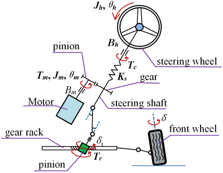
Simplified model of electric power steering system.
The dynamic analysis of the simplified steering system model shows that the relationship among pinion angle, motor angle and front wheel angle is as follows:
According to the structure sketch of the electric power steering system, the steering pinion is taken as the research object and its motion differential equation is given as
When the lateral acceleration of the vehicle is limited to be less than 0.4g and the front wheel angle is small, the tire can be considered with linear deformation without considering the change of tire characteristics caused by load variation. The vertical load F
bij,
the lateral force s
ij
and the resistance moment T
r
on the tire are as follows:
In the integrated control modeling, the yaw, roll and pitch motions of the vehicle body, as well as the lateral and vertical motions, are mainly considered. The simplified model is shown in Figs 2 to 4.
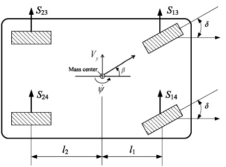
The entire vehicle steering model.
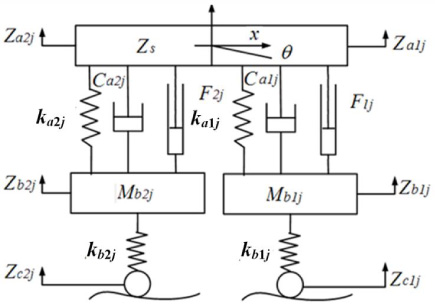
Pitch model of the whole vehicle.
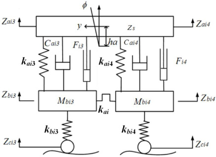
Roll model of the whole vehicle.
The lateral and yaw motions occur when the vehicle is steering. The force analysis of the steering model is carried out and the motion differential equation of the vehicle body is given as
The steering motion and uneven road surface also cause the vehicle body to roll and pitch. The differential equations of these two motions are as follows:
The differential equations of the vertical motion of sprung mass and unsprung mass are as follows respectively:
Based on the above EPS model, tire model and vehicle motion model, the integrated mathematical model of vehicle is established: the state vector is selected as
The above state vector is selected to ensure all of the vehicle motions mentioned above to be described and meanwhile the vehicle body, sprung mass, unsprung mass and tire to be modeled. Actually all the elements of the state vector form a maximum linearly independent group in the state space of the entire vehicle.
The input of EPS includes the power-assisted torque T
m
and the steering wheel angle exerted by the driver, and the input of ASS includes the active force F
ij
from four cylinders. Besides the road surface excitation z
cij
at four tires belong to extern disturbances, and also treated as the input for convenience of modeling. So the system input vector is defined as U = [F
13, F
14, F
23, F
24, T
m
, z
c13, z
c14, z
c23, z
c24, θ
h
]
T
, The output vector includes the feedback signals to realize the integrated MPC control, as well as the other signals we want to observe. The output vector is finally selected as
The differential equations of motion in Eqs ((8)) ∼ ((13)) are transformed into the state space expression as
The integrated control among the chassis subsystems can eliminate the conflicts among the different subsystems, improve the overall performance of the vehicle, and reduce the number of sensors and the complexity of the system. According to the predictive control theory, the integrated MPC is designed for the integrated model of active suspension and electric power steering systems. The schematic diagram of the integrated MPC control structure is shown in Fig. 5.
The prediction model uses the history information of the controlled vehicle:
The desired reference trajectory is defined as
The purposes of receding horizon optimization is to determine the future manipulated variable through minimizing the performance index, and this index can be described as
The conditions of receding horizon optimization are introduced as below: (1) The mechanical structure of suspension limits its dynamic deflection: |z bij − z aij | ≤ l max in which l max is the suspension stroke; (2) To ensure the tire’s grounding performance, the dynamic load should be less than the static load: |k bij (z cij − z bij )| ≤ Mg∕4; (3) The engine power restricts the hydraulic actuating force: |F|≤ F max in which F max is the maximum force which the vehicle can provide.
After applying the manipulated variables at the previous moment, the actual output y (k) is not equal to the prediction output of moment k because of the uncertainty of the EPS and ASS parameters and environment. The predictive error is then represented as
This error is weighted and then the prediction output is corrected
Substituting Eq. ((18)) into Eq. ((16)) and letting ∂J∕∂u = 0 results in the optimal control law as
The optimal control law for the current moment is
A certain type of off-road vehicle is taken as the test example, and its parameters are shown in Table 1. The system control model is further established in Simulink, The road surface excitation is based on the B-level random input model (Fig. 6).
Parameters setting of off-road vehicle
Parameters setting of off-road vehicle

Structural diagram of integrated MPC.

Excitation input of B level road surface.

Simulation results of vehicle body.
The simulation cases are set as follows: When the vehicle is running on B-grade road, the steering wheel angle is given a step input signal at 0 second, the initial jump value is 0 degrees, and the final jump value is 15 degrees. The main control parameters setting is as: P = 40, M = 30 and T = 0.005 s. The system simulation results of the integrated MPC of ASS and EPS are shown in Figs 7 to 9. The simulation results of passive control are also completed and presented in Figs 7–9 as the comparison to evaluate the integrated MPC. The passive control mode denotes that the ASS works at the passive mode without active force to input and meanwhile the EPS has no power assistance.
The statistics results of RMS (Root Mean Square) values of Figs 7 and 8 are presented in Table 2, which also includes the performance improvement of using the integrated MPC over the non-integrated passive control.

Steering wheel handling torque.
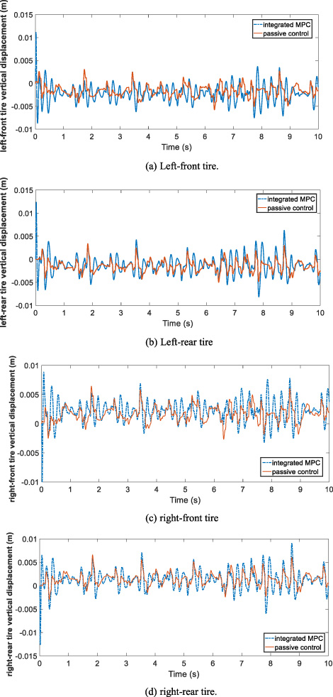
Simulation results of tire vertical displacements.
RMS statistics results comparison
From Figs 7 and 8 and Table 2, it can be seen that compared with passive control, the integrated MPC reduces the vehicle mass center slip angle, yaw rate, vehicle body vertical acceleration, steering torque needed on steering wheel by 4.80%, 5.51%, 59.60%, 79.18% in RMS values respectively, which means that the handling and smoothness performance, as well as the steering performance, have been improved. The decrease of 59.60% in vehicle body vertical acceleration is because of the factors peculiar to predictive control: actual output feedback information, real-time consideration of the impact of uncertainties and timely correction. These factors are integrated into the repeated online optimization process of the predictive and ensure the actual acceleration to approach the desire value and with large reduction.
The vehicle body slip angle and yaw rate are two indices to evaluate the handling stability when analyzing the vehicle response to angle step steering input. Smaller slip angle means that the vehicle longitudinal axis has no large deviation from the forward direction of the vehicle and still keeps the better driving stability. Similarly, smaller yaw rate or the rapid response to the desired yaw rate mean that the vehicle need not to do large adjustment to overcome the understeer or oversteer tendency, or the vehicle is able to quickly and accurately respond to reach the desired stable yaw rate state. Therefore the above improvements of 4.80% and 5.51% in slip angle and yaw rate, although not too large, stand for the rise in handling stability. Besides the more smoothly returning to zero value of roll angular speed of the predictive control relative to the passive mode in Fig. 7(c) also means the predictive control has better roll stability. Both the handling stability and the roll stability also mean the better driving safety.
The vertical displacements of all the four tires, namely z bij − z cij , are presented in Fig. 9, from which it can be seen that the tire vertical displacements in the integrated MPC mode are higher than those in the passive control. The reason for the higher displacements is that the integrated MPC uses the active suspension to improve the handling and smoothness performances of sprung mass, meanwhile to inevitably sacrifice some indices of unsprung masses. However the tires vertical displacements in the integrated MPC mode are still in the tolerant range of tires, and namely the previously mentioned load condition |k bij (z cij − z bij )| ≤ Mg∕4 is still satisfied. Besides this constraint, the other two constraints mentioned above: |z bij − z aij | ≤ l max and |F| ≤ F max are both satisfied all along.
Further the dynamic quality indices of EPS are measured according to the method of Literature [15]. The rise time, peak time, settling time and peak overshoot of vehicle yaw rate, which stand for the response characteristic of the steering system , are presented in Table 3 based on the simulation result of Fig. 7(b). From Table 3 it can be seen that the dynamic performance of the integrated MPC is distinctly better than that of passive model with at least 17.31% improvement. To summarize the above analysis, it can be concluded that the ride comfort, handling stability and driving safety of steering system and suspension system are all improved compared with the passive control.
Dynamic quality indices of EPS
To further testify the integrated MPC, the integrated optimal control design and simulation are also completed by us. According to the state space model in Eq. ((14)), the linear quadratic regulator (LQR) performance index is defined as
The steering lightness of EPS is further checked, and the steering wheel handling torque error indices are measured and presented in Table 4 in terms of ISE, IAE, ITSE and ITAE [15]. The torque error is computed relative to ideal zero torque and the smaller error values stand for better lightness. The results in Table 4 show that the integrated MPC has the best lightness performance in these three control modes.
Steering wheel handling torque indices
Vehicle body acceleration indices
The ride comfort of three control modes are further compared, and the vehicle body acceleration is used as the evaluating index in terms of ISE, IAE, ITSE and ITAE [15]. The ideal acceleration for best ride comfort is zero-value acceleration, which is taken as the desired value. Smaller error values relative to the desired value stand for better ride comfort. Table 5 shows that the integrated MPC obviously performs better than the passive control and the integrated optimal control.
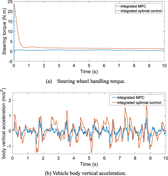
Comparison of integrated MPC and integrated optimal control.
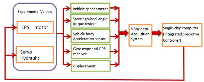
Diagram of experimental scheme.
After the above simulation verification, an experimental scheme is presented in Fig. 11. According to the output and feedback signals, the corresponding sensors and acquisition system are selected. The integrated MPC algorithm is programmed and stored in single-chip computer for on-board measurement and control experiment, which is the future work of this research.
The integrated MPC can be applied to off-road vehicle after its experiment succeeds. In some off-road occasions, for example forest fire patrol vehicles running on mountain roads in forest region, which need to improve their steering, handling and ride comfort on rough roads, can be equipped with the EPS, ASS and the integrated MPC controller.
The integrated mathematical model of steering system and active suspension system is established, and the model predictive controller is designed for the integrated model. The whole control system model is built in the simulation software and simulation with steering wheel given an angle step input under B-level road surface excitation is completed and analyzed. The simulation results show that the integrated MPC control effect of steering system and suspension system is better than that of passive control. the vehicle mass center slip angle, yaw rate, vehicle body vertical acceleration, steering wheel handling torque are improved by 4.80%, 5.51%, 59.60%, 79.18% in RMS values respectively, and the ride comfort, handling stability and driving safety of the vehicle have been improved. The comparison with optimal control further testified the performance of the integrated MPC.
The future research aims to complete the experimental verification of the integrated MPC of EPS and ASS, and further to apply it into special purpose off-road vehicle.
Footnotes
Acknowledgements
The research work is supported by the Heilongjiang Province Science Foundation (Grant No. LC2015019).
Appendix
Four matrices
(1) State matrix
(1) Non-zero elements the 1st row:
(2) Input matrix
The non-zero elements of
(3) Output matrix C:
The Non-zero elements of C are as follows:
(4) Direct feedthrough matrix
The non-zero elements of