
Abstract
By incorporating the merits of partitioned stator and flux modulation techniques, the partitioned stator flux modulation motors featuring high torque, have attracted much attention. This paper investigates four partitioned stator flux modulation motors with different types of PM arrays, including surface-mounted type, consequent-pole type, Halbach-array type, and half-Halbach type. The influences of key parameters on the average electromagnetic torque is conducted and compared. Then, based on the optimal designs, four motors are compared in terms of magnetic field distribution, back-electromotive force, torque characteristics, loss and overload ability. The result reveals that the half-Halbach motor is capable of utilizing more PM to improve electromagnetic torque. Also, the consequent-pole motor achieves the highest torque per PM usage. In addition, performance comparison under the same PM usage is carried out. The result shows that the half-Halbach motor not only exhibits the highest average torque but also achieves the highest PM utilization. Last, the prototype of half-Halbach motor is built for experimental verification.
Introduction
Stator-permanent-magnet motors have their unique characteristics of robust rotor structure, easy temperature management and excellent reliability etc., which are attracting great research interests [1]. However, their stators are quite crowded with both windings and PMs, whilst the rotor space is not fully utilized [2,3], leading to reduced torque density. To solve this problem, the concept of partitioned stator structure (PS) was proposed [4]. The PS motors feature two separate stators, which are employed to accommodate windings and PMs respectively. Also, an iron pieces rotor sandwiches between two stators. Thus, more space is available for both armature windings and PMs, which is beneficial to the torque density improvement.
However, most PS motors topologies have strict slot pole combination limitations [4,5]. It is because that these PS topologies are derived from the topology of stator-PM motors, including doubly salient PM motor, flux reversal PM motor and flux switching PM motor. Also, the resultant modulation ratios of these PS motors are low, which limits the improvement of the motor performance. On the other hand, it reported that flux modulation motor features high torque owing to its improved flux modulation effect [6–10]. Therefore, introducing flux modulation concept into PS motor becomes an effective solution to enhance PS motor performance.
Different types of PM arrays have significant impact on the motor performance and numerous literatures focused on various types of PM arrays. For example, Ref. [11] focused on the surface mounted PMs, Refs. [12–14] focused on consequent pole (CP) type and Refs. [15–17] focused on the Halbach PM array. These PM arrays have been applied to PS structure in [18–21], respectively. However, a comprehensive performance comparison of PS flux modulation motors with different PM arrays remains unreported hitherto.
Therefore, in order to provide a design reference for selecting an appropriate structure considering torque, torque ripple and loss, four PS flux modulation topologies with different PM configurations are comparatively studied in this paper. The paper is organized as follows. In Section 2, the topology, operation principle and torque production mechanism are introduced. In Section 3, the parametric analysis of four motors are presented. Then, in Section 4, the electromagnetic performance, including back electromotive force (back-EMF), torque characteristics, loss and overload ability are compared based on their optimal designs for the highest average electromagnetic torque. In Section 5, the prototype motor of the half-Halbach model is built and tested to verify the finite-element analysis. Finally, the conclusions are drawn in Section 6.
Topology and operation principle
Topology
Figure 1 presents four three-phase PS motors with 6/20 stator slot/rotor pole combination. Figure 1(a) shows PS-CP (CP) motor. The adjacent iron pole and PM pole constitute one pole pair. All the PMs are magnetized to the same direction. Figure 1(b) presents PS-SPM (SPM) motor. Figure 1(c) shows PS-Halbach (Halbach). Figure 1(d) demonstrates PS-half-Halbach (half-Halbach) PM array model. The magnetization direction of both Halbach and half-Halbach is specially presented in the picture.

Cross sections of four motors. (a) CP. (b) SPM. (c) Halbach. (d) Half-Halbach.
As shown in Figs 1(c) and 2(a), the Halbach structure often comprises PMs with different magnetization directions, namely tangential and radial directions. The adjacent magnets are either tangentially or radially magnetized. The magnetization directions of two adjacent radial magnetized magnets are opposite. Halbach PM array has the virtue of sinusoidal airgap flux density distribution and good self-shielding magnetization [15]. The sinusoidal airgap flux density is beneficial for torque density improvement and iron loss reduction. Figures 1(d) and 2(b) shows the half-Halbach array consists of one sandwiched radial and two tangential magnetized magnets, which are considered as a cell. In each cell, the magnetization direction of radial magnets and the size of two tangential PMs are kept the same.

Schematics of PM parameters. (a) Halbach. (b) Half-Halbach.
Double airgap motors are more complex and deserve further theoretical illustration compared with the conventional single-airgap ones. The rotor position in electrical degree can be determined by
Assuming that the inner and outer airgap still exists but irrespective of the modulated rotor, the tangential and radial flux density of inner airgap can be expressed as
The radial and tangential flux density of outer airgap, only produced by inner stator PMs, can be expressed as
The pole pair number of the modulated magnetic field can be expressed as
To obtain continuous and steady torque, the pole pair of windings (p
w
) should be equal to p
1,1 for its lowest order. In addition, the rotate speed of p
1,1 order magnetic field can be presented as
From the theoretical illustration presented above, it can be easily concluded that double airgap flux density calculation is complex. However, the PS motors share the same basic torque production mechanism with the single airgap motors.
In this section, the influence of key parameters on the average electromagnetic torque will be investigated based on 2-D finite element analysis.
PM parametric analysis
The PM-arc ratio k
cp
of CP motor is a key parameter for maximizing the output torque and is defined as
Figure 2 shows the defined parameters of the Halbach and half-Halbach array. As shown in Fig. 2(a), 𝛼
pm
is defined as the arc angle of a tangential and its adjacent radial magnetized magnet. 𝛼
i
is defined as the arc angle of the radial magnetized magnet. Then, k
Halbach
is defined as
Figure 2(b) shows the parameters of half-Halbach array. As illustrated, 𝛼 o is the arc angle of each cell and 𝛼 i is the radial magnetized magnet angle.
Figure 3 shows the PM thickness variation and its corresponding average electromagnetic torque. It can be observed that, for CP, SPM and Halbach model, the torque drops when the PM thickness increases. However, the torque of half-Halbach model increases before thickness reaches 5 mm. Hence, the PM thickness of CP, SPM, Halbach and half-Halbach are selected to be 2 mm, 2 mm, 2 mm, and 5 mm, respectively. Figure 4(a) shows that the CP structure achieves its best performance when pole-arc is around 0.65. Therefore, the optimal pole-arc of CP model is chosen to be 0.65. Figure 4(b) shows that the average torque increases before k Halbach reaches 0.7. Hence, the optimal value of k Halbach is selected to be 0.7. Figure 4(c) indicates that average torque reaches its maximum value when 𝛼 i is 7°. It also shows that the average torque first increases then descends when 𝛼 o ranges from 11° to 14°. The optimal values for 𝛼 o and 𝛼 i are 13° and 7°, respectively.

PM thickness optimization.
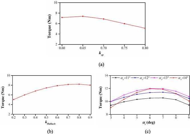
Parametric analysis. (a) Pole-arc optimization of CP model. (b) PM ratio analysis of Halbach model. (c) PM ratio analysis of half-Halbach model.
The key design parameters of rotor are illustrated in Fig. 5. The average electromagnetic torque versus rotor radial thickness h r is compared and presented in Fig. 6. The optimal h r value of the four models is around 4 mm. This is because thick rotor would reduce the space for PMs and armature windings, while thin rotor would cause high saturation.

Schematics of rotor parameters.
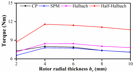
Rotor radial thickness analysis versus average torque.
The influences of rotor outer angle 𝛽 ro and inner angle 𝛽 ri are shown in Fig. 7. It can be found that appropriate values for 𝛽 ro and 𝛽 r would increase motor performance, since they would avoid flux-leakage and magnetic saturation. The average electromagnetic torque of the four models increase with rotor outer angle. However, after 12.5°, no obvious change in torque is observed. Hence, the optimal rotor outer angle value for four models is 12.5°. For rotor inner angle, the four models first increase then descend. Hence, the optimal values for models are around 6.5°.

Rotor outer and inner angle parametric analysis versus average torque. (a) Rotor outer angle versus torque. (b) Rotor inner angle versus torque.
The parameters of the outer stator are shown in the Fig. 8. The average electromagnetic torque and torque ripple versus outer stator tooth thickness are shown in the Fig. 9. Figure 9(a) shows that average torque decreases when tooth thickness increases. The torque ripple of the four models are sensitive to tooth thickness. It can be seen from Fig. 9(b) that the torque ripple increases when the tooth becomes thicker. The optimal values of tooth thickness for CP, SPM, Halbach and half-Halbach models are 0.5 mm, respectively.
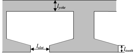
Schematics of outer stator parameters.
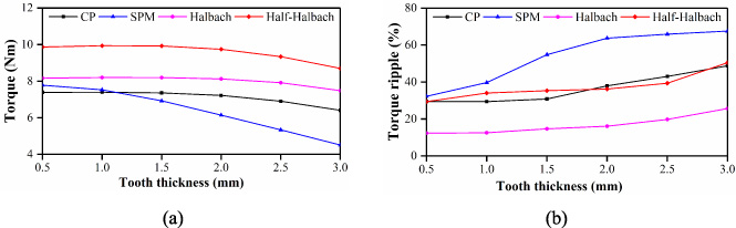
Tooth thickness parametric analysis. (a) Tooth thickness versus average torque. (b) Tooth thickness versus torque ripple.
The relations of the torque and slot opening width are shown in Fig. 10. It is clear that the slot opening width has great influence on the torque ripple. By compromising the torque and torque ripple, l slot = 4 mm is chosen as the preferred value for CP and Halbach model, and l slot = 2 mm is for SPM and half-Halbach model.

Slot opening parametric analysis. (a) Slot opening versus average torque. (b) Slot opening versus torque ripple.
Then, the relationship between average torque and the outer stator yoke thickness is presented in Fig. 11(a). On one hand, the average torque of all the four models first increase, then remains immune to the variation of the yoke thickness. The influence of the stator yoke thickness variation on the torque of the CP and Halbach models is not as obvious as half-Halbach model, since the half-Halbach model is more saturated than the other two models. On the other hand, torque ripple of four models decrease greatly when yoke thickness ranges from 2 mm to 4 mm because of saturation in the yoke. They remain unchanged when yoke thickness ranges from 4 mm to 8 mm. Hence, the optimal yoke thickness value for the four models is 4 mm.
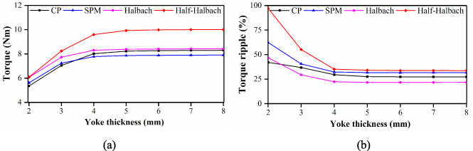
Yoke thickness parametric analysis. (a) Yoke thickness versus average torque. (b) Yoke thickness versus torque ripple.
The key design parameters are shown in the Table 1.
Key design parameters of the motors
In this section, the electromagnetic performance of the four motors is analyzed and compared. Their parameters are listed in the Table 1. The advantages and disadvantages of each motor will be summarized. For a fair comparison, the motors are compared under the same fixed current and identical rotational speed.
Magnetic field distribution
This part discusses magnetic field distribution from the perspective of both PM and armature windings. According to (16), when i = j = 1, the modulated magnetic field pole pair number is p 1,1 = 2. Figure 12 verified the theory from the perspective of flux distribution. All the models have 4 flux loops, which implies that the PM magnetic fields have 2 pole pairs. From the perspective of outer airgap flux density, as illustrated in Fig. 13(b), the main working harmonic is 2nd order which also implies that PMs produce 2 pole-pair magnetic field. It should be noted that, there exist other orders of harmonics at the same time i.e. 6th, 8th, etc. However, these orders are low in their amplitude compared to the main order, so these orders are often neglected. Furthermore, from the Fig. 13(b) it can be seen that the half-Halbach motor has the largest fundamental airgap flux density among the others. This is because that the half-Halbach motor is capable of utilizing more PM to exert the flux-focusing effect.
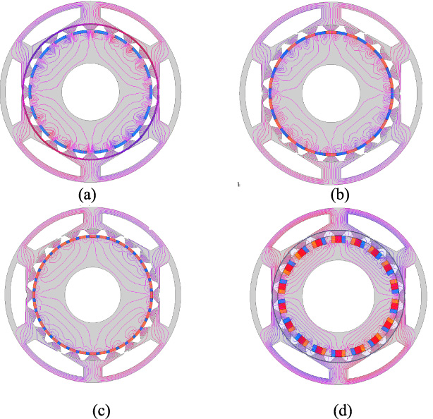
Magnetic Field Distribution of four motors. (a) CP. (b) SPM. (c) Halbach. (d) Half-Halbach.
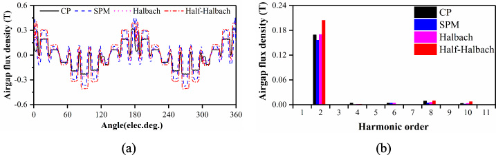
Outer airgap flux density. (a) Waveforms. (b) Harmonic analysis.
The armature reaction MMF is produced by injecting three-phase symmetrical and sinusoidal currents. To obtain continuous and stable torque, the pole pair of windings should be equal to p 1,1. It can be known that the armature reaction MMF contains the harmonics with 2k pole-pair (k = 1,2, … and k ≠ 3,6,9, …). Then, the armature reaction MMF will be modulated by the rotor in the inner airgap. Hence, the modulated harmonic orders of four models can be identified as: |2k ± jN r |(j = 0,1,2, …, ∞; N r = 20), which can be verified by the results shown in Fig. 14(c), where 2nd order of harmonic is the highest of all. 4th, 8th and 10th will also contribute to electromagnetic torque. In general, it can be concluded that 2nd order harmonic contributes most of the torque.
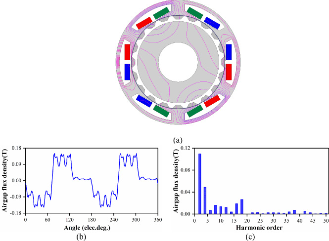
Inner airgap flux density. (a) Magnetic field distribution of armature winding. (b) Waveform (c) Harmonic analysis.
The back-EMF waveforms and its corresponding harmonic contents are compared in Fig. 15. It can be seen from the Fig. 15(a) that the back-EMF waveforms of the four models approximate to sinusoidal. For Fig. 15(b), the half-Halbach model exhibits the highest fundamental harmonic value of the back-EMF due to the highest 2nd order of flux density in the airgap. This order of harmonic is responsible for the 1st order harmonic in the back-EMF. Also, it should be noticed that there is a fraction of 2nd order harmonic in the back-EMF., which is negligible due to its low amplitude. The average torque and the torque ripple are listed in Table 2. When the rated current fixed to 5A, the SPM model shows the lowest average torque and the second largest torque ripple compared to others. Moreover, the half-Halbach model exhibits the largest average torque and its torque is almost 1.51 times higher than the SPM model. Also, the CP model shows the ability to achieve the highest torque per PM usage volume. Figure 16(c) presents the average torque versus currents. It can be found that the output torque of the half-Halbach model is always higher than the other three. Figure 16(d) shows current versus torque ripple. It can be seen that the torque ripple drops greatly when current ranges from 1A to 3A.
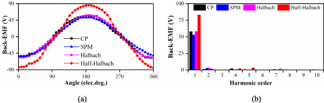
Comparison of back-EMFs. (a) Waveforms. (b) Harmonic analysis.
Torque comparison

Cogging torque and Average torque. (a) Cogging torque. (b) Average torque. (c) Torque versus input current (d) Torque ripple versus input current.
Generally, it can be concluded that all the four models have approximate sinusoidal EMF waveforms. The Halbach model exhibits the lowest torque ripple and the half-Halbach model achieves the highest average torque. SPM model produces lowest torque and CP model shows the potential of highest torque per PM usage volume. Also, the overload ability of the half-Halbach model have the advantages over all other models. Nevertheless, considering that half-Halbach model employs larger amount of PM material, it is important to compare the motor performance under the same PM usage volume, which will be discussed later.
As the optimization presented above, it can be found that, the outer stator slot opening width and PM thickness have greater influence on the torque and torque ripple. Therefore, to present the geometric structure of four motors more precisely, the outer stator slot opening width and PM thickness should be considered as 2 independent design variables. Two design objectives, i.e., maximum average torque and minimum torque ripple are chosen to achieve the optimal performances of four motors. The optimization progress in this paper includes: central composite design (CCD) sampling, response surface generating and multi-objective differential evolution (MODE) optimization. Firstly, four models are sampled by CCD, then a response surface is generated. Secondly, according to the response surface, four models are optimized by MODE, which has been proven to be one of the most powerful global numerical optimization algorithms to achieve a tradeoff design. The results are listed in Table 3. It is observed that design variables and objectives are close to initial values listed above.
Comparison of optimal values
The iron and PM eddy current losses versus speeds are shown in Fig. 17. Since the rated current of the four models are kept the same, the copper losses are same. The copper loss can be expressed as
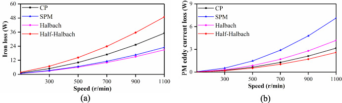
Loss. (a) Iron loss versus speed. (b) PM eddy current loss versus speed.
In the previous sections, four individually optimized PS motors are comprehensively compared and their characteristics are highlighted. However, different PM usage volumes in these machines are selected to maximize their average electromagnetic torque. The cost of the motor is mainly affected by the cost of PM material. The half-Halbach model exhibits the highest average torque but with maximum PM usage volume. Hence it is significant to analyze the motor performance under identical PM volume.
In the following comparison, the PM usage of the four models is fixed to 36 568 mm3. The other parameters are the optimal ones that analyzed above. The back-EMF waveforms and its harmonic components, torque and torque ripple, and overload ability are simulated and presented. The open-circuit phase back-EMFs at 500 r/min of these four PS motors are compared in Fig. 18. The back-EMF amplitude of half-Halbach model is still the highest, although the advantage is not as overwhelming as in previous simulation. This is due to the less PM usage volume in the half-Halbach model. The torque waveforms with excitations of 5 A current are presented in Fig. 18(c). The torque and torque ripple are presented in the Table 4. It is clear that under the same PM usage, the half-Halbach model still exhibits the highest average torque of the three. Hence, the half-Halbach model achieves the highest PM utilization rate. The overload ability of four models are similar.
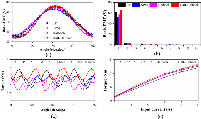
Comparisons under identical PM usage volume. (a) Back-EMF waveforms. (b) Harmonic analysis. (c) Torque and torque ripple. (d) Torque versus input current.
Torque comparison under identical PM volume
In this section, the PS motor with half-Halbach structure is manufactured. The prototype motor consists of three parts, i.e., outer stator with 6 slots wound by 6 concentrated armature coils, 20-pole rotor, and half-Halbach inner stator, as show in Fig. 19. The half-Halbach array was adhered firstly according to magnetization directions. Secondly, high strength glue was applied between PMs and inner stator slot. Then insert PMs in the slot and remove the extra glue. Finally, install the rotor after the glue solidifies. The experiment bench of the prototype is shown in the Fig. 20. The back-EMF is tested on the prototype motor to verify the simulation analysis. The measured and simulation phase back-EMF are compared in Fig. 21. As shown, good agreement is achieved between the measured and FE-predicted values.
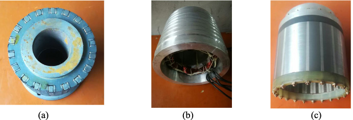
Photos of stator and rotor. (a) Inner stator. (b) Outer stator. (c) Rotor.
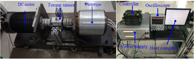
Experiment bench of the prototype.
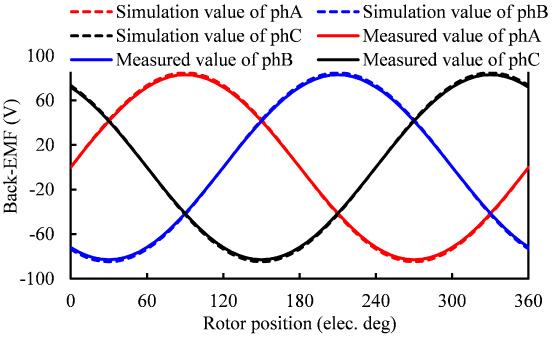
Simulation and measured value of back-EMF.
Four PS flux modulation motors with different inner stator topologies have been compared in this paper. The torque production mechanism and the double airgap flux modulation effect have been introduced. Under the same basic parameters, parametric analysis has been conducted. Then, the electromagnetic performances of the four motors have been compared. The simulation results have shown that the half-Halbach model exhibits highest average torque and the lowest PM eddy current loss, while the Halbach model achieves the lowest cogging torque and iron loss. Compared to other three models, the CP model achieves highest torque per PM usage volume. In addition, when the identical PM usage volume is applied to four machines, the half-Halbach model still exhibits the highest average torque but with less overwhelming advantage. Meanwhile, the SPM model shows the easiest manufacture process and the Halbach model exhibits the lowest torque ripple. The appropriate choice of PS machines depends on the specific applications. Finally, the half-Halbach array prototype has been built and tested. The test result is in good agreement with the simulation result.
Footnotes
Acknowledgements
This work was supported in part by the National Natural Science Foundation of China under Projects 51977099 and 51807082, in part by the China Postdoctoral Science Foundation under Project 2018M642179, in part by Natural Science Foundation of Jiangsu Higher Education Institutions under Project 18KJB470007, and in part by the Priority Academic Program Development of Jiangsu Higher Education Institutions.