
Abstract
In this paper, an improved Halbach array structure of a direct-drive linear motor for wave energy conversion is proposed, and its magnetic circuit structure is modeled and the induced electromotive force (EMF) generated by vertical wave energy conversion is deduced. Then, using the internal and external parameters of the wave energy conversion direct-drive motor, that is, four internal parameters of the magnetic circuit topology and two external parameters of the mover motion, the influence of these parameters on the induced EMF of the direct-drive motor in the wave energy conversion is analyzed. Since the theoretical analysis results of the model are consistent with the results of the two kinds of permanent magnet materials analyzed by the finite element method (FEM), the model and analysis method of the direct drive motor are correct. The investigation show that the modeling method proposed in this paper can be used to optimize the energy conversion of the direct-drive motor from two aspects: the internal parameters of the magnetic circuit topology of the direct-drive motor and the external parameters of the mover motion.
Keywords
Introduction
With the further development of wave energy, direct-driven linear generators [1,2], such as linear synchronous PM generators, flux-switching PM linear generators, and linear magnetic gear generators, stand out from many high-efficiency conversion schemes for wave power generation. Without gears and hydraulic systems, direct-drive linear motors have become a key point for improving power generation conversion. From the perspective of improving the conversion efficiency of direct-drive linear motors, the current literature mostly focuses on two aspects. One is the control method of the power generation conversion system, such as damping control [3–7], power control [8,9], power factor control [10], and other control methods [11,12]; the other is the design and optimization of the generator structure, especially the optimization of the electromagnetic topology. In terms of electromagnetic topology optimization, the optimization of permanent magnet structure has become an important point [13–21], such as magnet segmentation [13–15], trapezoidal magnet pole [16,17], creating magnet pole with different magnet materials [18,19], Halbach structure [20,21], etc. Due to the low energy density of ocean waves, the speed of ocean waves changes with time, and linear generators must operate at low speed and instantaneous speed change [21,22]. Therefore, the optimization of the electromagnetic structure of linear motors has become a key point of ocean wave energy conversion [23]. Traditional direct-drive motors for wave energy conversion rarely use Halbach magnetic pole structure, and even less use the improved Halbach. This paper mainly focuses on the improved Halbach topology based on the Halbach array, which is used for wave energy harvesting.
Combined with the reciprocating operation characteristics of the direct-drive linear energy conversion device, this paper proposes an improved Halbach array for wave energy conversion in low-speed motion, which is based on the improvement of the Halbach array and uses a magnetic circuit topology with different heights of radially magnetized permanent magnets and axially magnetized permanent magnets. It not only has the characteristics of unilateral self-shielding effect of Halbach array [14,20,24], but also reduces the cost of permanent magnets without significantly reducing the air gap flux density. In Section 2, the magnetic circuit model of the improved Halbach array is first established. Then, based on the magnetic circuit, the no-load electromotive force generated by the motor armature driven by the monochromatic wave is deduced. Finally, two kinds of permanent magnets are used to verify the structure magnetic circuit and no-load induced electromotive force by the finite element method. The proposed wave energy conversion model is correct. In Section 3, the influence of the main parameters of the Halbach array structure on wave energy conversion is discussed. The conversion of waves into electromotive force is analyzed from six parameters of array structure parameters and mover motion parameters.
The contributions of this paper are (1) a direct-drive motor using Halbach array that can reduce the volume of permanent magnets is theoretically modeled and verified by the finite element method, and (2) the internal parameters and external parameters of the wave energy conversion motor, that is, the four parameters of the array structure and the two parameters of the mover motion, are used to jointly analyze the conversion motor, and use it for the design and optimization of the motor.
Design and analysis
Magnetic circuit modeling
Due to the regularity of its magnet arrangement structure, the magnetic circuit model is used to analyze the improved Halbach structure used in this paper, which is an effective method and can achieve a certain engineering accuracy [25]. Figure 1 shows the no-load magnetic circuit model of the improved Halbach magnet array, in which the red arrows indicate radial magnetization magnets, and the blue arrows indicate axial magnetization magnets. The heights of the axial magnets and the radial magnets are unequal. The heights of the axial magnets and the radial magnets are unequal. The no-load magnetic flux path and the equivalent magnetic circuit within a pair of poles are drawn with lines in Fig. 1.
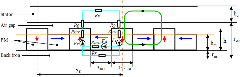
Schematic diagram of the no-load magnetic circuit model of the improved Halbach structure.
The magnetic field of the Halbach array is enhanced on one side, and weakened on the other side, even to zero, so the magnetic flux leakage of the array in the axial direction can be ignored. In the derivation of this paper, an assumption is made, that is, the iron core works in an unsaturated state, the core magnetic resistance R
c
is ignored, and other leakage magnetic fluxes such as slot leakage magnetic flux and inter-pole magnetic flux leakage are also ignored. According to Kirchhoff’s law of magnetic circuit, in one magnetic pole, Eq. ((1)) can be obtained.
Substituting Eqs ((2)), ((3)) and ((4)) into Eq. ((1)), the magnetic flux of the magnetic circuit can be expressed as ((5)).
Since the leakage flux is ignored, the working flux density is the air gap flux density, that is, B
m
= B
g
. The magnetic density obtained by the above formula (7) is the constant average magnetic density under the pole arc of the permanent magnet, and the amplitude in the pole arc of the positive half cycle is always positive B
m
, and the amplitude in the pole arc of the negative half cycle is always negative B
m
. Since B
m
is an oddly symmetric waveform in the period, the Fourier trigonometric function expansion of this waveform can obtain that both the DC component and the cosine component are zero, that is, a
0 = 0 and a
n
= 0, and the sine component is the expression (8).
Therefore, taking the value of n in Expression (10) as 1, the fundamental wave Expression (11) of the magnetic flux density can be obtained.
The direct-drive wave energy linear power generation belongs to the reciprocating power generation system. One of its key features is that the mover of the linear motor reciprocates in the vertical direction with the wave. Assuming that driven by an ideal monochromatic wave, the motor mover exhibits sinusoidal motion, and its reciprocating displacement can be expressed by Eq. (13).
Since the electrical angular displacement θ
ae
of the linear motor is the product of the mechanical angular displacement θ
r
and the number of pole pairs P, and the mechanical angular displacement is also related to the pole distance τ and the motion displacement x, the motion displacement can be converted into electrical angular displacement, that is,
Since the three-phase windings of the linear motor are symmetrical in space, that is, each phase winding occupies one third of the cycle, so by rewriting the parameter θ
ae
containing the spatial position information of the induced voltage Eq. (15), the three-phase induced electromotive force of the wave reciprocating motion is given by the following Eqs (16), (17) and (17), respectively.
In order to extract maximum power from a reciprocating linear motor, the phase current of the motor must be in phase with its no-load induced phase electromotive force, and this condition can be achieved by PWM control of the current phase [8]. Therefore, the three-phase current expressions of the reciprocating linear motor can be expressed by Eqs (19), (20) and (21), respectively.
In the previous part of the magnetic circuit structure model and the induced electromotive force, the induced electromotive force of the linear generator that reciprocates with the wave is deduced. This mainly analyzes the correctness of the induced electromotive force of the improved Halbach model with the wave motion. In this part, the correctness of the derivation in this paper is verified by simulating the two magnetic circuit parameters of the improved Halbach array model in commercial finite element analysis software. Due to the symmetry of the magnetic circuit, this paper uses the parameters in Table 1 to establish an analysis model of the number of pole pairs, and the magnetic flux line of the model is shown in Fig. 2, where the x-direction represents the motor axial direction, and the z-direction represents the motor radial direction. It can be found that the self-shielding effect on the left side of the Halbach permanent magnet is better.
Parameters of the modeled motor
Parameters of the modeled motor

The magnetic flux lines of a pair of poles of the motor model.
Firstly, the parameters of the first magnetic circuit structure model used in the simulation are shown in Table 1, and the simulation results of the single-phase induced electromotive force are shown in Fig. 3. Assuming that the monochromatic wave drives the linear motor mover to do reciprocating motion, there is no energy loss, that is, the linear motor mover moves with the wave, and the movement frequency of the mover is the frequency of the wave. The main parameters of the monochromatic wave used in this paper are a height of 0.2 meters and a period of 2 s.

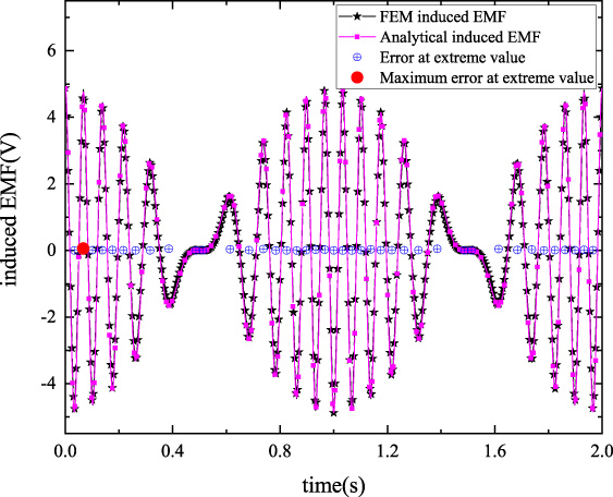
Analytical, finite element method no-load induced electromotive force for Magnetic Circuits in NdFeB, and their errors at extreme value.
Figure 3 express the single-phase induced electromotive force of analytical analysis and finite element analysis under the same motor model parameters and monochromatic wave parameters, and clearly show the frequency and time-varying amplitude obtained by these two methods.
The single-phase no-load electromotive force in this figure is obtained in the sinusoidal motion period of 2 s, and the sinusoidal envelope frequency of the electromotive force is equal to the frequency of the reciprocating motion of the direct drive motor, that is, the period is also 2 s. At the same time, it can be clearly observed from the figure that the induced electromotive force obtained by FEM is basically the same as the waveform trend of the electromotive force obtained by analytical calculation, that is, their frequency, phase and amplitude are basically the same.
It can also be seen from Fig. 3 that the error between the FEM electromotive force and the analytically calculated electromotive force is mainly concentrated at the extreme value of the induced electromotive force. The maximum error occurs at 0.0672 s, the error value is 0.2030 V, and the proportion of the error in the voltage amplitude is 1.52%.
Secondly, in order to further verify the analytical calculation, the simulation uses the second type of magnetic circuit structure model parameters, and the simulation results of the single-phase induced electromotive force are shown in Fig. 3. In order to have better comparability, the difference in the structural parameters of the two magnetic circuits is only the difference in the permanent magnetic material of the Halbach array. That is, the permanent magnet materials of axial magnetization and radial magnetization of the motor magnetic circuit in Fig. 3 are all NdFeB permanent magnet materials with residual magnetic density of 1.14T, and the permanent magnet materials magnetized in both directions in Fig. 4 are all ferrites with a residual magnetic density of 0.4T.
Analytical, finite element method no-load induced electromotive force for Magnetic Circuits in ferrite, and their errors at extreme value.
It can be observed from Fig. 4 that the error between the FEM electromotive force and the analytically calculated electromotive force is mainly concentrated at the extreme value of the induced electromotive force. The maximum error occurs at 0.0672 s, the error value is 0.0569 V, and the proportion of the error in the voltage amplitude is 1.18%.
Finally, based on the finite element simulation analysis of the previous two magnetic circuit structural parameters, the simulation results of the single-phase induced electromotive force have a good match with the analytical calculation results, and the envelope period of the electromotive force is consistent with the monochromatic wave period, so the simulation results show that the analytical calculation deduced in this paper is correct and can be used for subsequent research and analysis.
In this part, two aspects are discussed on the influence of induced electromotive force, namely, the magnetic circuit topology parameters and the mover motion parameters.
First, the influence of the parameter changes of the improved Halbach topology on the no-load electromotive force of wave conversion is analyzed, and four variables τ, 𝛼, 𝛾 and 𝜅 are set. where, 𝛼 is the ratio of the radially magnetized permanent magnet width to a pole pitch in the magnetic circuit structure, and the expression is (23); 𝛾 is the proportional relationship between the number of motor poles and the pole pitch, and the expression is (24); and 𝜅 is the ratio of the height of the axially magnetized permanent magnet to the radially magnetized permanent magnet in the magnetic circuit structure, and the expression is (25).
Figure 5 shows the single-phase induced electromotive force with different proportions 𝛼 of the width of the radially magnetized permanent magnet in a magnetic pole. Without changing the τ value, the amplitude of the sinusoidal envelope of the single-phase induced electromotive force has a downward trend with the increase of the radially magnetized magnet width ratio 𝛼. But the single-phase induced electromotive force waveform does not change the period and the number of extreme points with the increase of 𝛼.
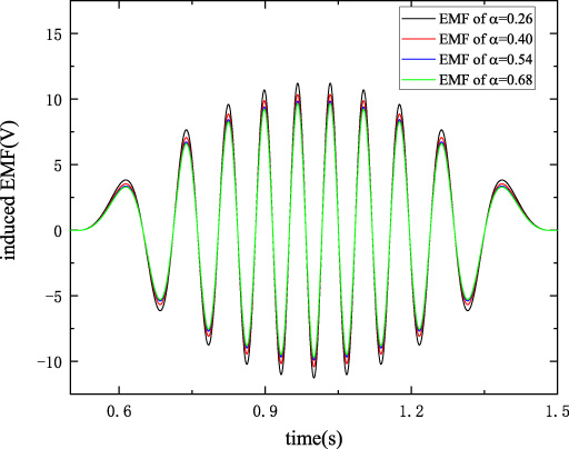
Half-cycle single-phase induced electromotive force with different proportions 𝛼 of radially magnetized permanent magnet width in the magnetic pole.
Figure 6 depicts the single-phase induced electromotive force of the ratio 𝜅 of the radial magnetization to the axial magnetization width. From the waveform in Fig. 6, it can be found that the period, the number of extreme points, and the change trend of the potential waveform with the 𝜅 value are consistent with Fig. 5, that is, the parameters 𝜅 and 𝛼 have the same influence on the single-phase induced electromotive force. It can also be observed from Fig. 6 that when the array structure parameter 𝜅 decreases from 1 to about 0.7, the single-phase potential amplitude of the direct-drive motor changes little, and when 𝜅 drops over 0.7, the single-phase potential amplitude of the direct-drive motor changes greatly. This feature can be used to optimize the amount of permanent magnets used, while the single-phase potential amplitude changes little. That is, the usage amount of the permanent magnets is reduced due to the unequal heights in the axial direction and the radial direction, thereby reducing the usage cost of the permanent magnets.
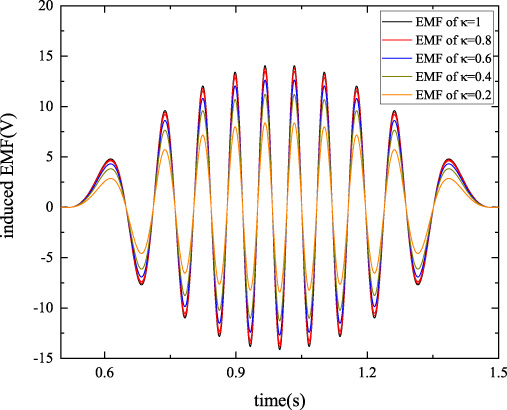
Half-cycle single-phase induced electromotive force with different values of 𝜅.
Figure 7 shows that, in the case of fixed τ, the amplitude of the sinusoidal envelope of the single-phase induced electromotive force has a tendency to increase with the increase of 𝛾, the polarity change of the induced electromotive force in half a wave cycle is accelerated, and the number of the extreme points increases.
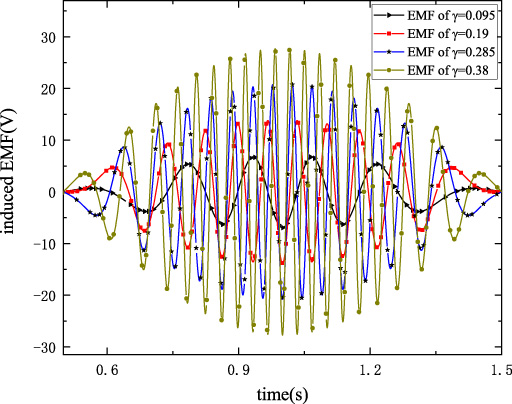
Half-cycle single-phase induced electromotive force with different values of 𝛾.
Figure 8 shows that the amplitude of the sinusoidal envelope of the single-phase induced electromotive force has a tendency to increase with the increase of τ, the polarity change of the induced electromotive force within half a wave cycle is weakened, and the number of extreme points is reduced.
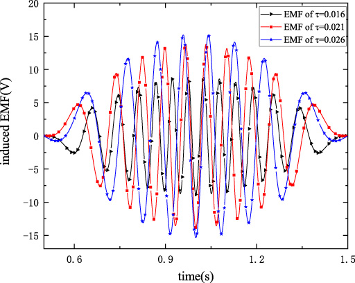
Half-cycle single-phase induced electromotive force with different values of τ.
In addition, the influence of the reciprocating motion parameters of the mover on the no-load electromotive force is also analyzed, and two variables are set, namely the period T and the input drive signal x superimposed by the three components.
As the external wave frequency that drives the motor movement changes, that is, the wave period changes, the induced potential of the motor changes as shown in Fig. 9. It can be seen from the figure that as the wave period increases, the amplitude of the sinusoidal envelope of the single-phase induced electromotive force decreases, and the period of the potential waveform increases. And the period of the potential waveform is consistent with the wave period that drives the mover to move.
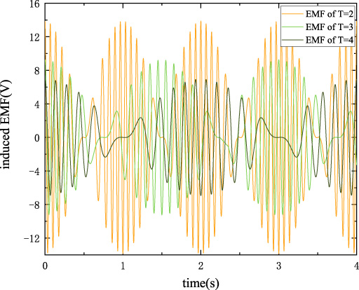
Single-phase induced electromotive force for wave period T.

Single-phase induced electromotive force of drive signal x superimposed by three components.

Single-phase induced electromotive force of drive signal x combined by three-section wave.
The driving signal x of the complex wave moving in the vertical direction can be decomposed into the superposition of the fundamental wave and multiple harmonic motions through Fourier decomposition. Assuming that the motion in the vertical direction is decomposed into the red waveform in Fig. 10, the waveform expression is (26). Driven by this red motion waveform, the single-phase induced electromotive force of the motor is shown as the black waveform in Fig. 10. In the figure, it can be observed that when the motion waveform is at the extreme value, the obtained single-phase potential is 0, mainly because the velocity is 0 at the extreme value of the displacement. The greater the difference between the two extremes, the greater the amplitude of the sinusoidal envelope of the single-phase induced potential. The period of the potential is equal to the period of the fundamental wave of the drive signal x, and the maximum value of the potential also occurs at the derivative of the fundamental wave of the signal x.
On the other hand, a three-section combined wave on the basis of the three-component narrowband wave (26) is added as an input signal, and drive the motor. The input waveform is as in formula (27), and the output voltage waveform is as in Fig. 11. It can be observed from Fig. 11 that when the monochromatic wave is input for 0–2 s, the single-phase voltage waveform envelope is sinusoidal, and the envelope period is consistent with the input wave period. The two intervals of 2–4 s and 4–6 s are input waves for multiple component combinations. The single-phase potential (10) obtained by the input wave (27) driving the motor is consistent with the characteristics of the single-phase potential (9) of the input wave (26).
This paper introduces the magnetic circuit modeling of an improved Halbach permanent magnet linear motor for ocean wave energy extraction, and deduces the no-load electromotive force formula generated in the energy conversion under sine wave direct drive. This can be used to optimize the Halbach structure topology and analyze the effect on no-load EMF. The Halbach permanent magnet structure uses high-coercivity NdFeB permanent magnets as the main and auxiliary magnetic poles of unequal heights, which reduces the usage of the permanent magnets without significantly reducing the air-gap magnetic flux density. Firstly, the magnetic circuit model of the direct-drive linear motor for wave energy extraction is established, and then the electromotive force generated by the monochromatic wave drive is analyzed, and the finite element method is used to verify it. Finally, the influence of the magnetic circuit topology and mover motion on the single-phase no-load induced EMF is analyzed when the direct-drive motor reciprocates with the waves. However, since the conversion of wave energy into motor no-load EMF and power is highly dependent on the improved Halbach topology of the direct-drive linear motor, additional studies using the analytical methods presented in this paper are required.
Footnotes
Acknowledgements
This work was funded by a project that partially funded by National Science Foundation of China (51675265), the Advantage Discipline Construction Project Funding of University in Jiangsu Province (PAPD), and the Independent Research Funding of the State Key Laboratory of Mechanics and Control of Mechanical Structures (0515K01). The authors gratefully acknowledge this support.