
Abstract
In this paper, the winding inductances of a linear ironless permanent-magnet synchronous actuator for high-precision applications is discussed. Different from rotary motors for conventional applications, high-order harmonics and the end effect due to discontinuous structure are considered. From such considerations, an improved Fourier series expansion is applied to the proposed distributed-parameter model of the linear winding. The calculated inductance matrix is of high accuracy, and presents a new non-uniform form. New features of the inductance matrix are analyzed, and the decoupling scheme is implemented via variable transformation and real-time updating inductances.
Introduction
At present, the inductances of a permanent-magnet (PM) synchronous actuator are mainly modeled considering its air-gap character, especially for a rotary actuator. However, geometric asymmetry is intrinsic to a linear synchronous actuator due to its open structure. This spatial discontinuity results in high-order harmonics of magnetic field and other physical quantities. On the other hand, end effect of a linear actuator is considered to model the magnetic field distribution and the thrust force [1]. But it is seldom discussed to find out its impact on inductances [2]. This may work for conventional applications, whereas may not for high-precision applications.
On the basis of the classic vector control theory, the inductance matrix of a PM synchronous actuator needs to be diagonalized through the dq0 transformation. Otherwise, control strategies will fail due to the coupling between the d- and q-axis. For salient or non-salient pole rotary synchronous motors in conventional applications, the traditional dq0 transformation works. However, for linear actuators in high-precision applications, high order harmonics contribute a lot and cannot be neglected. On the other side, the discontinuous structure together with its end effect will produce a new form of the inductance matrix. Therefore, it remains for researchers to accurately model the inductance matrix to study its new characters and the related decoupling strategy under high-precision requirements.
Inductances can be calculated from the definition or the magnetic energy. Both are essentially in accordance and in terms of the magnetic field distribution. So calculation of the winding inductances of a linear actuator relies on accurate modeling of the magnetic field distribution, both in description of high-order harmonics and end effect. Compared with the conventional permeance method [3,4] and current sheet method [5,6], the analytical or semi-analytical method on the basis of the Fourier series harmonic expansion is more precise in calculation of magnetic field distribution. Meanwhile, it is time-saving and more efficient in computational costs and design optimization, compared with the classic finite element method (FEM) [7,8]. Accordingly, Fourier series expansion is more widely applied by researchers. A sectioned linear PM synchronous machine used in electromagnetic aircraft launch system was studied by Li et al., where both the self and mutual inductances of the sectioned winding are modeled and validated by experiments [9]. To further describe the end effect of linear actuators on winding inductances, Ma et al. developed a combined method based on the traditional Fourier series expansion, where the end leakage magnetic field was approximated by vector potential initially obtained by FEM [10]. Similarly, for a tubular linear machine, Yan et al. proposed an analytical method based on harmonic expansion, where the end magnetic field was modeled by equivalent circuits [11]. These impressive work contributes a lot and inspires much. However, it is based on empirical assumptions to describe end field distribution by equivalent circuits or vector potential, and the combination makes implementation of the methods cumbersome. Besides, to calculate the slot leakage inductances for fractional-slot concentrated-winding machines, the magnetic energy method was employed in the slot region [12]. In this case, magnetic flux is mainly concentrated in the slot, so integration of energy density within the slot will not lose much accuracy.
It is worth mentioning that in recent years the modified winding function theory has shown its advantage in analyzing rotor eccentricity to develop a diagnosis technique [13,14]. Later, it was applied to inductance calculation of interior permanent magnet motors [15] and tubular linear motors [16]. However, since this modified winding function is derived from an iron-core application, it will fail when applied to coreless applications. Moreover, it is only suitable for PM machines with small air gap of arbitrary shape rather than large air gap [13,16].
Since ironless cores are usually utilized in precision engineering, in this paper, the inductance matrix of a linear ironless PM synchronous actuator is concentrated on. An improved Fourier series expansion is developed to directly describe the end magnetic field, and a distributed-parameter model of the winding is proposed to accurately calculate the inductances. Consequently, new features of the inductance matrix are revealed, the related decoupling problem is discussed. The rest of the paragraph is organized as follows. Section 2 introduces the traditional inductance model, Section 3 builds the present accurate inductance model, the related transforming and decoupling problems are discussed respectively in Sections 4 and 5, and finally conclusion is made in Section 6.
Traditional inductance model
First, new concepts are defined to simplify the description. Homogeneous mutual inductances are defined to derive from the same two coils, while heterogeneous mutual inductances derive from different coils. For example, the mutual inductance M AB of coil A induced by coil B and its reciprocal inductance M BA are homogeneous, while M AB and M AC are heterogeneous.
Usually, the inductance matrix of a rotary motor is symmetrical, namely, the homogenous mutual inductances are equal. From the viewpoint of vector control, the heterogeneous mutual inductances need to satisfy some relation to ensure that the inductance matrix can be decoupled. There are two situations for this relation. One is for salient pole rotary synchronous motors, which are based on the second order harmonic model of the air-gap permeance and geometrical symmetry of the three-phase winding [17]. The other is for non-salient pole rotary synchronous motors, which are characterized by equal heterogeneous mutual inductances due to uniform air-gap permeance. Specifically, the above inductance matrices can be written respectively as
In general, the above two inductance models for rotary synchronous motors satisfy conventional requirements in engineering. However, linear synchronous actuators are not so ideal due to their intrinsic spatial asymmetry, which will be discussed in the next section.
Present inductance model
Without loss of generality, Fig. 1 illustrates the longitudinal section of a linear ironless PM synchronous actuator for precision engineering. The primary is the stator of the three-phase winding. a w and b w are the width and height of the winding coils, respectively, and τ w is the width of the virtual slots. A Halbach PM array is utilized as the x-translating mover.
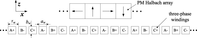
Topology of the linear ironless PM synchronous actuator.
As shown in Fig. 2, the origin of the coordinate system of the three-phase winding locates at the center. For clarity, only one winding unit is illustrated to stand for the total N w winding units.

The three-phase winding.
Apply three-phase sinusoidal current I
ph
, where ph = 1,2,3 denotes the winding of phase A, B and C, respectively. Let N
c
denote the number of turns per phase winding, then the phase current density is
In order to consider the spatial discontinuity of the winding, an improved Fourier series expansion with a long period is applied [1,18]. That is, duplicate the three-phase winding along the x direction to infinity with a spacing of 2τ s , which is selected large enough to neglect the influence between windings. Consequently, the end effect of the linear winding is approximated.
Thus the current density is expanded as
According to the distribution of magnetic source, the magnetic region is divided into three parts, i.e., region I above the winding (
By applying the technique of variable separation, it yields
Considering
The inductances of a winding with an iron core are traditionally modeled with lumped parameters due to the magnetic-concentrated character of the iron. In this section, the inductance matrix is calculated based on the distributed-parameter model of the linear ironless winding, in which the actual winding process is considered. As depicted in Fig. 3, the cross-section of the winding is divided uniformly into N c sub-sections by N c1 columns and N c2 rows. In each sub-section, the magnetic flux density is approximated by that of the center.
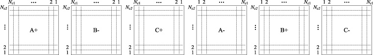
Region division of the three-phase winding.
In the k-th winding unit (k = 1,2, …, N
w
) of phase i (i = 1,2,3), a single-turn coil with coordinate of (t
1, t
2) (t
1 = 1,2, …, N
c1, t
2 = 1,2, …, N
c2) crosses from x
lb
to x
ub
, i.e.,
Then the associated flux linkage through the phase-i winding due to the phase-ph winding is
Thus in the k-th winding unit the inductance of the phase-i winding in terms of the phase-ph winding is
The winding units are connected in series, so the total inductance of the phase-i winding in terms of the phase-ph winding is
Alternatively, 𝜓
i, ph, k
can also be calculated through magnetic potential. That is, substitute
If the sum in (16) is replaced with double integral, it yields
It is noticed that the inner and fringe winding units both contribute in the above calculating methods in terms of flux density or magnetic potential, therefore the end effect of the winding is considered.
The inductance matrix of the linear winding is validated by the Maxwell software. The associated parameters are listed in Table 1. Set the configuration of phases A, B and C, and apply each phase with positive or negative currents. Connect the positive and negative coil sides of each phase to form a closed loop, and then group the loops of the same phase. Finally, the inductance matrix can be obtained after simulation and observed in the post-process module. As listed in Table 2, the mutual inductances are not completely equal in the symmetric inductance matrix. Exactly speaking, the homogeneous mutual inductances are equal, but the heterogeneous inductances may be not, i.e., M AB = M BC ≠ M CA . Apparently, the inequality is caused by the spatial discontinuity of the linear winding. For simplicity, hereinafter, an inductance matrix with equal heterogeneous mutual inductances is defined uniform, and an inductance matrix with unequal heterogeneous mutual inductances is defined non-uniform. Obviously, the inductance matrix of the present linear ironless three-phase winding is non-uniform.
Parameters of the winding
Parameters of the winding
Inductance matrix obtained by Maxwell
For comparison, the inductance matrix is respectively calculated by the flux density- and magnetic potential-based distributed-parameter models and the lumped-parameter model (referred to as D1-Flux density, D2-Potential I, D3-Potential II, L1-Flux density and L2-Potential I, respectively), all of which are on the basis of the improved Fourier series expansion. The obtained non-uniform inductance matrices are listed in Table 3, in which the associated winding models and calculating methods of flux density are marked for comparison. In Table 3, the terms distributed and lumped respectively stand for the distributed- and lumped-parameter model, and the terms improved and traditional respectively stand for the improved and traditional Fourier series expansion. It can be observed that the inductances obtained by distributed-parameter models are very close to those of the Maxwell, that is, the relative error is no more than 0.2% for the self-inductance, and no more than 0.6% for the mutual inductances. Meanwhile, the lumped-parameter model is much less accurate than the distributed-parameter model, e.g., the relative error of the self-inductance can reach as high as 7.5% for the former, whereas it is only 0.2% for the latter. This is mainly because the distribution character of the winding process is fully considered in the distributed-parameter model.
Comparison of inductances obtained by different methods
It is noticed that based on the same distributed-parameter model of the winding and the improved Fourier series expansion of the flux density, there are slight differences by applying different calculating methods of inductances. Specifically, the results of D1-Flux density and D2-Potential I are no doubt the same, because they share the same calculating formulas, i.e., (11) or (16). The D2-Potential I and D3-Potential II are generally of the same accuracy, and the tiny discrepancy derives from the difference between the sum of finite number of values and the integral.
Besides, based on the distributed model of the winding, the inductances are also calculated by applying the traditional Fourier series expansion, which is referred to as D4-Traditional in Table 3. As can be seen, the inductance matrix is uniform and much less accurate. Apparently, by applying the traditional Fourier series expansion, the open structure of the linear winding is neglected and therefore its end effect is not revealed.
Inductances can also be obtained by their relation to magnetic energy [12], i.e.,
In the present study, the ironless linear winding is applied to precision engineering, where the non-uniform feature should be under consideration. However, it is worth mentioning that such non-uniform feature exists in all linear windings, coreless or cored, since it results from the asymmetry of the linear structure. Table 4 lists the inductances of the ironless, iron-core slotless and iron-core slotted linear windings, which are illustrated in Fig. 4. They can be calculated by the Maxwell software, or the present improved Fourier series expansion plus new boundary conditions in terms of the iron core and the Carter coefficient considering the effect of slots [20]. It is observed that the self-inductances with an iron core are not equal with a small difference. This is due to the finite length of the linear iron core. Phase B is in the middle of the winding, and phases A and C are at the end of the winding. So flux of phase B goes mainly out of the upper surface of the iron core, unlike those of phases A and C, part of which pass from the left or right side of the iron core. Comparatively, there is no such difference for the ironless winding because of the uniform permeability in the winding space. On the other hand, the small difference between self-inductances will cause decoupling after the dq0 transformation. Actually, adjustment of the length of the iron core contributes a lot to minimization of the detent force [21–23].
Inductances of coreless and cored linear windings
Inductances of coreless and cored linear windings
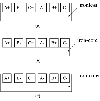
Linear winding types: (a) ironless, (b) iron-core slotless, (c) iron-core slotted.
Secondly, all the inductance matrices are non-uniform in the linear winding, no matter coreless or cored, and slotless or slotted. To describe the physical asymmetry of the linear winding, define
Third,
It is worth mentioning that in the method of improved Fourier series expansion, the linear winding is considered as a whole, and all magnetic sources are integrated in one period. Therefore, it can also be applied to fractional-slot linear windings, either overlapped or non-overlapped. Its accurate analytical form is available for study of slot-pole combination both in computational cost and description of physical meaning.
As mentioned above, the uniform inductance matrix can be decoupled completely via the dq0 transformation. However, it does not work for the present non-uniform inductance matrix. Thus the decoupling scheme need to be amended based on the dq0 transformation in particular.
The non-uniform inductance matrix is rewritten in the ABC three-phase coordinate system as
By applying the dq0 transformation,
As shown above, the non-uniform inductance matrix is not completely diagonalized by applying the dq0 transformation. On one side non-diagonal coupled terms L
aij
(i ≠ j) are generated in the transformed non-uniform part
Let L
ij
(i, j = 1,2,3) denotes the component of
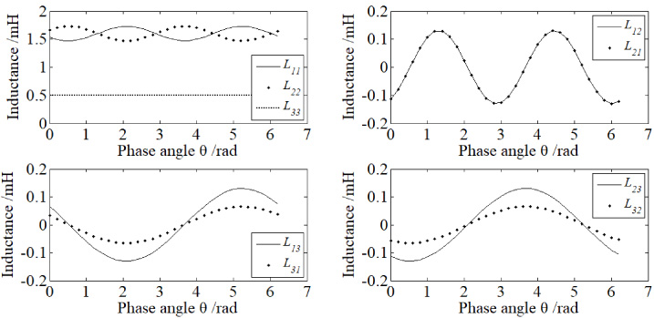
Inductances via dq0 transformation in terms of phase angle.
As shown above, the d- and q-axes still couple after the dq0 transformation is directly applied to the non-uniform inductance matrix. In spite of this, it seldom affects the sinusoidal form of the output winding currents. Fig. 6 demonstrates the output winding currents obtained through the uniform and the non-uniform inductance matrices respectively by applying three-phase sinusoidal voltages into the winding, and Fig. 7 shows their difference. They are very close to each other with an error much less than 1 mA. Consequently, the key problem of decoupling the non-uniform inductance matrix depends on the coupling terms between the d- and q-axes, not the negligible current distortion.
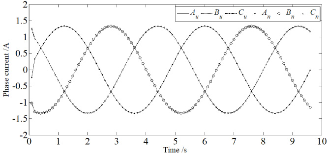
Currents obtained through the uniform and non-uniform inductance matrices.
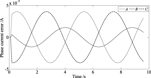
Current error between the uniform and non-uniform inductance matrices.
In the electrical model of the linear PM actuator, the three-phase voltage
Let
Usually, a PM actuator is driven by three-phase voltages, and then currents are generated in the electrical circuit of the actuator. Thus, substitute (26) into (25), then derivative of currents can be rewritten as
Finally, the d- and q-axes are decoupled via variable transformation, although the inductances are in terms of the phase angle. It is worth mentioning that the sampling frequency of a real controller is much higher than the mechanical frequency of the actuator. Therefore, the inductances can be updated within a few sampling periods while the actuator works under the instructions of the control system. Consequently, the differential dynamic system with variable coefficients can be regarded of constant coefficients due to the real-time updating inductances.
This paper focuses on the accurate winding inductance model of a linear ironless PM synchronous actuator for precision applications. Based on the improved Fourier series expansion and the proposed distributed model of the linear winding, the inductance matrix is accurately calculated given the end effect of the asymmetric structure and the winding process. Different from the traditional uniform form, the present inductance matrix is non-uniform. Based on this new feature, the non-uniform inductance matrix is transformed and then decoupled via variable transformation and the real-time updating scheme for precision control.
Besides, it is worth mentioning that the non-uniform feature is intrinsic to linear windings, no matter it is iron or ironless, slotless or slotted, overlapped or non-overlapped, and integer-slot or fractional-slot, for which the present improved Fourier series expansion is also applicable.
Footnotes
Acknowledgements
This work was supported by the National Natural Science Foundation of China under grant 51875333 and Public Projects of Zhejiang Province (LGF19E050003), for which the author is grateful.