



Abstract
For precision engineering, a linear PM-moving actuator with trapezoidal PMs and trapezoidal coils considering the fringing effect is proposed. To take into account the effect of the finite-long trapezoidal PM array, an improved Fourier series expansion is developed to calculate the fringing-included magnetic field. Then the full-stroke thrust excited by the trapezoidal coils is accurately predicted and validated by the finite element method. Sensitivity of the trapezoidal parameters of PMs and coils is analyzed, and combined optimization is implemented by the genetic algorithm. Through the Pareto optimal solutions of thrust, the relation of the PM-coil parameter combination is described and formulated by curve fitting. Compared with the traditional rectangular PM actuators or other trapezoidal-typed actuators, the proposed actuator with trapezoidal PMs and coils further decreases the thrust ripple and largely increases the thrust magnitude simultaneously, and reaches an utmost-close effective stroke as well.
Keywords
Introduction
Linear permanent magnet (PM) actuators have been widely used in precision engineering [1], where both high thrust magnitude and low thrust ripple are required. High thrust magnitude can improve the dynamic response ability of the actuator, while low thrust ripple affects the motion accuracy. Generally, thrust ripple of linear air-cored PM actuators for precision engineering is caused by two factors, the fringing effect due to finite length and high-order harmonics of magnetic field, both of which rely on accurate modeling of the magnetic field and the associated optimization process.
Compared with the conventional permeance method [2,3] and current sheet method [4,5], the analytical or semi-analytical method on the basis of the Fourier series harmonic expansion is more precise in calculation of magnetic field distribution. Meanwhile, it is time-saving and more efficient in computational costs and design optimization, compared with the classic finite element method (FEM) [6,7]. Therefore, Fourier series expansion is widely applied to magnetic field calculation. However, it will fail to describe the fringing effect of finite-long PM array or winding, because Fourier series expansion is mathematically based on periodic functions. To overcome this shortcoming, Ma et al. developed a combined method based on the traditional Fourier series expansion, where the end leakage magnetic field was approximated by vector potential initially obtained by FEM [8]. Similarly, for a tubular linear machine, Yan et al. proposed an analytical method based on harmonic expansion, where the end magnetic field was modeled by equivalent circuits [9]. These impressive work contributes a lot and inspires much. However, it is based on empirical assumptions to describe fringing field distribution by equivalent circuits or vector potential, and the combination makes implementation of the methods cumbersome. Consequently, for PM-moving actuators, Fourier series expansion needs to be improved for finite-long applications.
From the viewpoint of design, low thrust ripple can be achieved by appropriate arrangement of the magnetic poles, such as optimizing the pole arc coefficient [10], using modular poles [11], utilizing pulse-width-modulated PMs [12], adding auxiliary poles [13], adjusting skewing angle and pole-arc coefficient [14], segmenting the armature [15] and so on. Since PMs usually provide most of the air-gap magnetic field and different PM parts contribute non-uniformly [16,17], one simple and effective method is shape optimization of the PMs [18,19]. In order to achieve better force performance as well as improve potential usage of the PM material, different curve-edged PM poles have been developed, such as arc edges [20,21] and eccentric edges [22] for rotary PM actuators, and arc edges [23–26], step-shaped edges [27], sinusoidal edges [28] and other curved edges [29] for linear PM actuators. These curved edges are impressive and result in satisfying performances of magnetic field or thrust.
However, considering the complicated manufacturing process and the high economic costs, these curved edges may not be very applicable in engineering practice. Therefore, the feasible and low-cost trapezoidal PMs recently return to be focused on for multi-objective optimization. Systematic work on trapezoidal PM linear synchronous motors at multi-speed has been investigated by Dong et al. [30]. Various approaches have been proposed to analyze the magnetic field distribution of trapezoidal PMs [31–34]. In addition, impressive work has been done on thrust optimization of double-layer reverse skewed coils by Wang et al. [35]. All the above work for linear motion was aimed at winding-moving actuators, so fringing effect of the PM stator was not taken into consideration.
In precision engineering, where low thrust ripples are more concerned, the PM-moving actuator is a more available choice. Thus the intrinsic fringing effect of the PM mover comes first into consideration. Besides, to further reach a better thrust performance, the cooperating relations between the PMs and the coils need to be considered. At present, only the single contribution of PM parameters or coil type is focused on. The PM-coil parameter combination has seldom been paid attention to for an optimized result, even though the effect of both stator and PMs was simultaneously considered. For instance, trapezoidal shape was just applied to both the PMs and the slots in the dual-rotor axial flux machine [36], values of stator and rotor pole arcs were directly set to show the low noise level [37], and only shape combination of stator teeth and pole shoes was discussed [38].
In the previous paper [39], the author has proposed an improved analytic method and applied it to a rectangular PM actuator for decoupling control. In this paper, an ironless PM-moving linear actuator with trapezoidal PMs and trapezoidal coils is proposed for precision engineering. In order to accurately describe the longitudinal fringing effect of PMs, the traditional Fourier series expansion is improved by a long period. Subsequently, both the magnetic field and thrust are well predicted in Section 3. To further enhance the thrust performance, effects of the trapezium parameters are analyzed in Section 4, and the PM-coil parameter combination is investigated through the Pareto optimal solutions in Section 5. Finally, Section 6 draws the conclusion.
Actuator topology
Without loss of generality, Fig. 1 illustrates the longitudinal section of an ironless Halbach PM actuator with trapezoidal PMs and coils for precision engineering. As the primary, the stator consists of a three-phase trapezoidal winding and its aluminum frame. a w , b w and θ w denote the middle width, height and slope angle of the trapezoidal coils, respectively, and τ w is the virtual slot pitch of the winding and equal to τ∕3. As the mover, a finite-long PM Halbach array is also trapezoidal-shaped and can translate along the x direction. a v and a h are respectively the middle width of the vertically and horizontally magnetized PMs, and b and θ p are respectively their height and slope angle. The pole pitch τ is equal to a v + a h .

The actuator topology.
Field distribution
To reveal the fringing effect of the finite-long PM array on magnetic field distribution, the traditional Fourier series expansion is improved by duplicating the PM array along the x-axis to infinity with a spacing of 2τ s . The value of 2τ s is selected large enough so that the influence between PM arrays is negligible. Thus the fringing-included field distribution of the PM array is approximated.
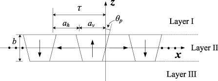
Layer model of the PM array.
As shown in Fig. 2, the magnetic field analysis of the ironless trapezoidal Halbach PM array is confined to three layers, namely, the air layer I above the PM array
Since only the y-component of
Let
Therefore, by applying the method of variable separation, the magnetic flux density components in layer III are solved as
The thrust force exerted on the mover results from the interaction between the three-phase winding current and the magnetic field due to the PM array. Supply the three-phase winding with sinusoidal current
According to the Lorentz force law, the thrust force due to one phase of the winding is
Substitute Eq. ((8)) into Eq. ((12)), then by applying the integral operation, it yields
Consequently, the actuator thrust is obtained as
To validate the proposed analytic model based on the improved Fourier series expansion, the finite element calculation was implemented through the Maxwell software. The traditional analytic model, utilizing 2τ as the fundamental period, was also carried out for comparison.
Design parameters of the trapezoidal-shaped PM actuator
Design parameters of the trapezoidal-shaped PM actuator
The main design parameters of the PM actuator with trapezoidal PMs and coils are listed in Table 1. The material of the PMs is NdFe30 with B r = 1.1 T and μ r = 1.045, and three-phase currents with I m = 2.81 A and f w = 0.318 Hz are applied to the trapezoidal winding.
Both the flux density and the thrust are calculated. By adjusting the current phase angle, the largest thrust with a specified displacement is obtained, according to the actuator controlling scheme. As illustrated in Figs 3 and 4, the flux density obtained by the improved analytic model and by the finite element agrees perfectly with each other, both in magnitude and the fringing deterioration. Similarly, the thrust forces obtained by the improved analytic model and by the finite element calculation also match very well within the utmost stroke range of [−2τ,2τ], as shown in Fig. 5. They both accurately show the thrust decrease caused by the intrinsic fringing effect. That is, the thrust decreases largely when the PM mover translates near the stroke end of the actuator (Δx = −48 mm), compared with that in the middle of the stroke. Besides, the thrust fluctuates with a period of 8 mm, which results from the real 5th and 7th order spatial harmonics. This main source of thrust ripple needs to be optimized to satisfy precision requirements.

B x obtained by the analytic model and the finite element model (red solid line represents Maxwell, blue dots represent Analytic-improved and black circles represent Analytic-traditional).
However, the thrust obtained by the traditional analytic model is quite different from that of the finite element calculation. The fringing effect is not represented because the PM array is assumed to be infinitely long. Therefore, to accommodate to the interaction between the PMs and the winding, only the flux density under the PM array is utilized to calculate the thrust, i.e., supposing only the N p winding units under the PM array are applied. As shown in Fig. 5, the obtained thrust is smaller than the benchmark, due to neglect of the magnetic field outside the PM array. Alternatively, if all the N w winding units are applied, the thrust will become N w ∕N p times as large as that of the above case, and the thrust deviation will get even worse. Consequently, the traditional analytic model is not applicable for PM-moving actuators.

B z obtained by the analytic model and the finite element model (red solid line represents Maxwell, blue dots represent Analytic-improved and black circles represent Analytic-traditional).

Thrust force obtained by the analytic model and the finite element model.
To further validate the effectiveness of the improved analytic model, an experiment was set up to measure the actuator thrust. Due to easy manufacturing and low cost, a rectangular Halbach PM array was used. As illustrated in Fig. 6, the winding is connected with two z-directional displacement adjusters to adjust the air-gap thickness. The PM arrays are connected to the sliders of a ball screw-slider mechanism to realize the x-directional translation. Once the PMs are adjusted in place, the sliders are fixed by screws to keep stationary. The three-dimensional force sensor KISTLER 9317b is mounted between the PMs and the sliders. When the actuator force is generated, electric charge signals are produced in the piezoelectric ceramic material of the force sensor, and then transmitted to the charge signal amplifier DEWE-RACK-4 for signal condition, e.g. filtering, isolating etc. The sensitivity of the force sensor is 25.65 pC∕N. Set the output measuring range of the charge signal amplifier to 2000 pC, then a measuring range of about 78N is obtained for the force-testing system. The data acquisition board is utilized to accept the output charge signal of the charge signal amplifier, implement A/D conversion and transmit the digital data to a PC for analysis. Values of the force are finally obtained through dividing the input data of the PC by the sensitivity of 25.65 pC∕N. Supply the winding with three-phase sinusoidal currents, and then the acquisition of thrust data is started manually through the acquisition software in the PC. The thrust force is finally recorded in terms of time.

Photo of the experimental setup.
Supply the winding with a current amplitude of 1.41 A and 2.81 A, and adjust the air-gap thickness g to 2 mm and 3 mm, respectively. Figure 7 demonstrates the thrusts obtained by the experiment, the Maxwell software and the improved analytic model, which are respectively represented by the dash line, the dots and the solid line. Obviously, the two computational results, i.e., those obtained by the improved analytic model and Maxwell, match very well. Besides, the amplitudes of the computational and the experimental waveforms are very close to each other, and the phase difference between them is constant as expected. Due to the manual starting of thrust acquisition, the initial phase of the experimental waveform is different in each experiment, depending on the starting moment of acquisition, while the initial phase of the computational waveforms remains constant. Therefore, a constant phase difference indicates the coincidence between the experimental and computational results in frequency.

Thrusts obtained by the experiment, Maxwell and the improved analytic model (‘- - -’ for the experiment, ‘⋯’ for Maxwell and ‘—’ for the improved analytic model).
Generally, there are three types of geometrical parameters for the PM array and the winding, the vertical, the horizontal and the air-gap. It is empirically regarded that vertical parameters are largely related to magnitude of forces per unit mass or volume [41], and horizontal parameters contribute to both thrust and its ripple. A small air-gap can increase the magnetic field, but a larger harmonic distortion can be simultaneously caused. Therefore, to make a compromise between the thrust magnitude and ripple, combination of horizontal parameters of the PM array and the winding needs to be investigated. As a consequence, middle widths and slope angles of the trapezoidal PMs and the coils are selected to be optimized.
Introduce dimensionless widths 𝛼 and 𝛽 as well as slope angles θ
p
and θ
w
as the optimization variables, where
The maximum effective current density is
Therefore, the constraint conditions are
Due to the fringing deterioration of thrust, the median thrust F m and the thrust ripple F r within [−τ, τ] is introduced as the optimization objectives to evaluate the force performance. The thrust ripple is defined as the difference between the maximum and minimum thrust within the domain.
To illustrate the effects of the optimization variables, four cases are discussed, i.e., Case 1 of varying 𝛼 and 𝛽 with θ p = 0° and θ w = 0°, Case 2 of varying 𝛼 and θ p with fixed 𝛽 and θ w = 0°, Case 3 of varying 𝛽 and θ w with fixed 𝛼 and θ p = 0° and Case 4 of varying θ p and θ w with fixed 𝛼 and 𝛽. Values of other fixed parameters are set as those in Table 1.

Median thrust and thrust ripple of Case 1.

Median thrust and thrust ripple of Case 2.
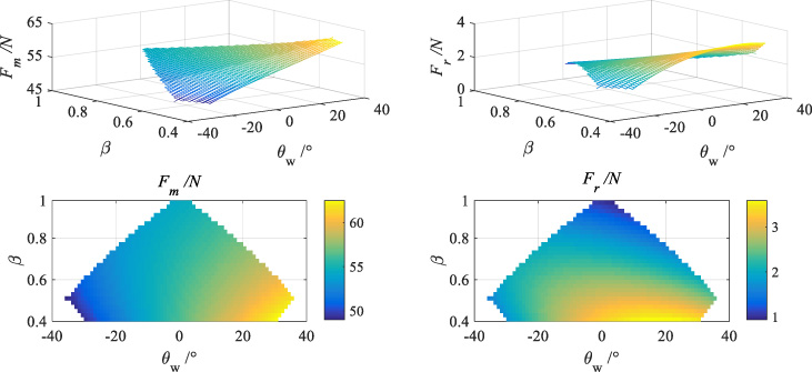
Median thrust and thrust ripple of Case 3.
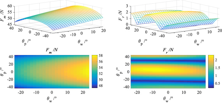
Median thrust and thrust ripple of Case 4.
Figures 8–11 show the median thrust and the thrust ripple of all the four cases in the forms of the 3D curved surface and its 2D projection. Obviously, 𝛼 plays a significant role in both the values of the median thrust and thrust ripple. θ w is related largely to the median thrust and moderately to the thrust ripple, and an increased value of θ w can lead to a large median thrust. Contrarily, θ p is related largely to the thrust ripple and little to the median thrust, and an appropriate value of θ p can lead to a very small thrust ripple. While applying constant currents, 𝛽 has little impact on the median thrust, and moderate impact on the thrust ripple. Alternatively, the winding can be applied with constant current density. However, in engineering applications, it is more concerned how large a thrust and its ripple can be produced under the action of constant currents or energy. Therefore, constant currents are applied in the present analysis.
In summary, the impacts of the optimization variables can be qualified and quantified on a scale of one to ten in Table 2, in which the priority is 𝛼 > θ w > θ p > 𝛽. As can be seen, although the winding generally only contributes about 10% of the magnetic field of the actuator, it still affects the median thrust heavily and the thrust ripple moderately. Thus it is necessary to make combined optimization for the parameters of the PMs and the coils.
Impacts of the optimization variables on thrusts
As shown above, the median thrust and the thrust ripple conflict in their essence. To reach a compromise for such multi-objective optimization problems, the traditional approach is to set up a preference function by weight coefficients or threshold values; then standard single-objective optimization methods can be used to find the optimum.
However, there are several drawbacks. Firstly, the weights or thresholds depend on individuals empirically, which results in individual optimal solutions. Secondly, the obtained single solution is supposed to be globally optimal. It is not clear whether it is non-dominated or not, and where it locates with respect to the Pareto front. Thirdly, it is of large computational burden. To obtain the Pareto front in terms of the non-dominated solutions, a series of single-objective optimizations should be implemented, which makes it inefficient and loosely attractive.
Consequently, the Genetic Algorithm (GA) is applied to the combined optimization of the present trapezoidal PMs and coils to search for the non-dominated solutions. Then selection of the Pareto points is left to the designer who can express the final preference a posteriori. The optimization flowchart based on the improved analytical model is depicted in Fig. 12.
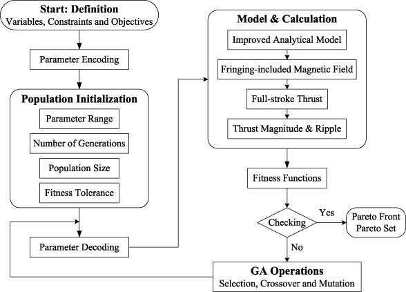
Flowchart of GA optimization for the improved analytical model.
To obtain the Pareto front, the initial population with the size of 100 is evolved 800 generations. The fitness tolerance is set as 10−4. Figure 13 illustrates the Pareto front of the present PM actuator with trapezoidal PMs and coils. Obviously, there is a knee point of F m = 60.98 N and F r = 0.25 N, which is preferred from the view point of precision engineering.
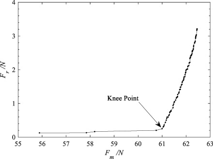
Pareto front of the present PM actuator with trapezoidal PMs and coils.
Figure 14 compares the Pareto fronts of different cases, namely, the traditional PM actuator with rectangular PMs and coils (Case 1), the PM actuator with trapezoidal PMs and rectangular coils (Case 2), the PM actuator with rectangular PMs and trapezoidal coils (Case 3) as well as the present PM actuator with trapezoidal PMs and coils. Obviously, compared with the traditional PM actuator with rectangular PMs and coils (Case 1), trapezoidal PMs can slightly reduce the thrust ripple at the cost of decreasing the median thrust, while the trapezoidal coils can largely increase the median thrust at the cost of increasing the thrust ripple. When the trapezoidal PMs and coils both work, i.e., in the present case, the thrust ripple are slightly decreased and the median thrust are largely increased simultaneously. Take the knee point of the Pareto front for example. As shown in Table 3, at the knee point, the median thrust and the thrust ripple of the present PM actuator respectively increase by 12.1% and decrease by 41.9% compared with those of the traditional PM actuator with rectangular PMs and coils (Case 1), and the relative thrust ripple reduces to only 0.41%.
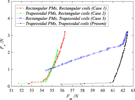
Pareto fronts of different cases.
Knee points of different cases
Pursuant to the sequence of F
r
from least to most (also referred to as the sequence of Pareto front hereinafter), distribution of parameters 𝛼, 𝛽, θ
p
and θ
w
is shown in Fig. 15. Generally, they concentrate well except the first few points. The first few points before the knee point are insignificant and neglected for precision applications, because the thrust ripple remains at a very small value, while the median thrust sequentially increases rapidly. After passing through the knee point, 𝛽 and θ
w
slightly vary around the fixed values of 0.42 and 31. 27° respectively, and 𝛼 and θ
p
slightly vary around oblique lines. In this domain, 𝛼 and θ
p
can be fitted as
It is worth mentioning that for the PM actuator with trapezoidal PMs and rectangular coils(Case 2), on the right side of the knee point, 𝛼 and θ
p
are also fitted as
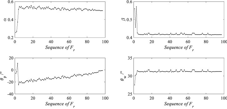
Parameter distribution along the Pareto front.
As a consequence, the Pareto PM-coil parameter combination is formulated by Eq. ((15)) as well as 𝛽 = 0.42 and θ w = 31.27°. The associated Pareto front is shown in Fig. 16, which matches very well with the original. In practice, selection of the Pareto combining points from the formula depends on engineering requirements and designers’ preference.
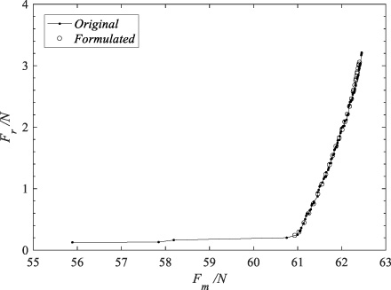
The original and formulated Pareto fronts.
To evaluate performance of linear PM actuators, effective stroke and relative ripple are also introduced, which are largely associated with the median thrust, the thrust ripple as well as the fringing effect. Effective stroke is defined as the translating range of the actuator confined by a certain value of thrust ripple. Relative ripple F rr is defined as F r ∕F m . It is worth mentioning that relative ripple is not appropriate to be used as a single optimization objective, since it cannot exactly describe the thrust requirement of a high magnitude and a low ripple. As shown in Fig. 17, the relative ripple F rr shares the same trend as the thrust ripple F r . It is focused on when a specific value of the relative thrust ripple is required in some applications.
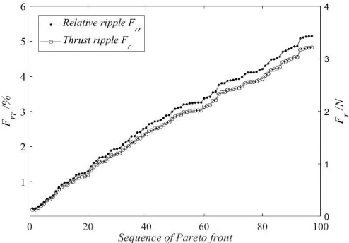
Relative ripple along the Pareto front.
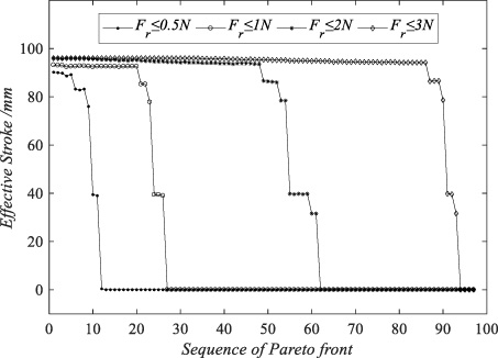
Effective strokes confined by different values of thrust ripple.
Figure 18 demonstrates the associated effective strokes when the thrust ripple F r is respectively confined to be less than 0. 5N, 1N, 2N and 3N. The utmost physical stroke of the present actuator is 96 mm. Obviously, the lower the thrust ripple is required, the shorter the effective stroke is in general. Zero value of the effective stroke means that the thrust ripple required is beyond the ability of the actuator. It is noticed that in the starting part of the Pareto front sequence, the effective strokes approach the physical utmost under different ripple confinements, the values of which are close to each other. Therefore, from the view point of achieving a longer stroke, the knee point takes priority to be selected due to the relatively high median thrust, the low thrust ripple and the utmost-close stroke length.
A linear PM-moving actuator characterized by trapezoidal PMs and coils is proposed for precision engineering. By applying the proposed improved Fourier series expansion, the fringing-included magnetic field of the trapezoidal PM array is reformulated, which is quite different from the rectangular PMs. Then given the currents of trapezoidal coils, the fringing-weakened actuator thrust of full stroke is calculated and validated. The derived formulae provide an effective method to describe the intrinsic fringing effect due to the PM mover’s finite length, as well as its impact on both the magnetic field and thrust.
To reach a compromise between the thrust magnitude and ripple, the Pareto optimal solutions are obtained through GA-based PM-coil-combined optimization. Due to the cooperation of the trapezoidal PMs and coils, the proposed trapezoidal-typed actuator can simultaneously achieve high thrust magnitude and low thrust ripple, as well as an utmost-close effective stroke, compared with traditional rectangular- or trapezoidal-typed actuators. Hence, the Pareto PM-coil parameter combining relation is revealed and formulated to guide a quick and optimal design of similar actuators.
Footnotes
Acknowledgements
This work was supported by the National Natural Science Foundation of China under grant 51875333, as well as the Starting Fund of Scientific Research of Jiaxing University (CD70519053), for which the author is grateful.
Coefficients for flux density
The undetermined coefficients