
Abstract
In this letter, an efficient and electrically compact cavity-backed self-triplexing antenna using a substrate integrated waveguide (SIW) technique is proposed. The antenna model is nested with an inverted “T”-shaped cavity and convert the rectangular SIW cavity into the two quarter mode (QM) and a half mode cavity (HM) approximately; excited through a coax probe and two micro-strip feed line separately. The proposed model operates at three distinct frequencies at 9.37 GHz, 9.86 GHz, and 10.36 GHz used for X-band wireless and radar communication systems. The self-triplexing feature is obtained with the mode perturbation concept and adequate intrinsic isolation of >31 dB is observed among three input ports. The proposed antenna possesses a minimum frequency ratio, uni-directional radiation patterns with high gain, and better efficiency.
Introduction
Recently, the advancement in radio-frequency (RF) has reached the peak of precedent discovery day by day. In which the multiple antennas are used for specific applications are replaced by a single antenna named the multiband antenna. This antenna has compactness, low fabrication cost, and better performance ability than the multiple antennas. So, the demand for multiband antenna increases rapidly [1–3]. It has the inherent feature of having the number of transceivers operating at different frequency bands. The metamaterial-based multiband antenna structure also plays a significant role in communication systems due to its attributes to improve the antenna’s performance like reduced electrical size and enhance the gain, bandwidth, and radiation efficiency. The implementation of metamaterial/metasurface in the domain of antenna and transmission line [4,5]; generally involves the designing of parallel capacitance and shunt inductance that provides a negative phase shift altogether by the inter-digital capacitor and stub inductor, respectively [6]. In [7,8] presents a planar and compact band-pass filter (BPF) and quad-band notch filter using metamaterial concept produces a broad stop-band suppression level, minimum insertion loss (<0.4 dB), and maximum overall rejection (>20 dB) at unwanted frequencies, respectively for the wireless power transfer (WPT) applications. In [9] describes a compact metamaterial-based multiband antenna using a modified Triangular Split Ring Resonator (TSRR) for the wireless local area network (WLAN), worldwide interoperability for microwave access (WiMAX), and international telecommunication union (ITU) band applications. Still, it also bears the disadvantages of complex geometry, higher interferences, and reduced isolation among the input ports. Therefore, an extra circuitry like a diplexer or triplexer (frequency-selective element) is required to find the minimum interference and excellent isolation levels among the consecutive frequency bands.
A triplexer is helped out to suggest an ordinary input signal into three separate output streams in the form of three distinct bands in the tri-band system. It incorporated three BPF with a matching network and combining circuit. The combining circuit provides the connection between the triple filter and single antenna; ensures the high isolation among frequency bands, as shown in Fig. 1(a). Numerous concepts are used to maximize the channel spacing between the transmitter and receiver to increase the isolation by triplexer element. It will enlarge the size of the overall system. Triplexer design using the decoupling network with the printed circuit board (PCB) also increased the system’s space and complexity. In [10] describes a passive S-band triplexer using the complementary split-ring resonator (CSRR) imprinted over the ground plane as coupled lines and interdigital capacitor in the patch (top) plane of the structure used to amplify the coupling levels. The structure has lower insertion loss (<2 dB), adequate isolation levels (>20 dB) and good fractional bandwidth (5%). However, it maximizes the structure complexity and needs a larger space to be inbuilt, as displayed in the block diagram of the triplexer shown in Fig. 1(a). As an outcome, new kinds of self-diplexing and self-triplexing antennas are installed in [11–15] independently to eliminate the diplexer or triplexer requirement and assemble the simple and straightforward RF front-end system defined in Fig. 1(b) [16].

Primarily block diagram of (a) tri-band antenna and (b) self-triplexing antenna system in transmitting and receiving mode.
Currently, the substrate integrated waveguide (SIW) based antenna technology is highly demanded for the wireless communication system. Previously, the microstrip-based structure and conventional metallic type waveguide are generally used for wireless communication purposes. The SIW has a number of assets in terms of high quality-factor, better power handling capacity compared to microstrip designs and light-weight, compactness in design, and minimum fabrication cost compared to the conventional metallic waveguide [17–19]. SIW based slot antenna is presented in [20,21] with improved parameters as enhanced bandwidth, high gain and radiation efficiency, and better front-to-back ratio (FTBR). Many articles are based on self-diplexing and self-triplexing techniques in the current research and depend upon the SIW platform [22–27]. In [23] represents the self-triplexing antenna having the “T”-shaped slot inside the SIW cavity and divided it into two quarter mode (QM) and a half mode (HM) cavity with poor gain and average cross-polarization levels than the proposed one. In [13], an integrated triplexer antenna with good isolation value is implemented using a double-layered substrate and the multi-mode excitation technique; this complexity of the overall structure increases. A self-triplexing antenna [24,25] shows better in-band performance, but it consumes a large space to operate and a reasonable gain with average radiation efficiency than the proposed self-triplexer antenna.
In [28] describes the compact structure of the self-triplexing antenna consists of a rectangular HM SIW cavity having adequate isolation (>20.5 dB), lower FTBR (>14), and lower impedance bandwidth of 0.10 GHz at all resonating frequency. While [29] presents a self-triplexing antenna that depends upon the concept of integrated SIW cavity and produces the acceptable isolation of >26 dB and minimal impedance bandwidth of better than 0.02 GHz at triple operating frequencies.
An electrically compact SIW based cavity-backed triplexer design is reported for the X-band wireless applications in this article. Here, the nested type triplexing antenna is implemented by an inverted “T”-shaped metallic cavity inside the main SIW cavity. Each radiated cavity combined with distinct three slots is excited by three separate feed-lines and produces the three resonating frequencies with adequate isolation better than 31 dB and acceptable impedance bandwidth (>0.23 GHz) at each operating frequency. This phenomenon describes the self-triplexing functionality of the proposed antenna. The presented antenna also possesses the property of frequency tunability at each operating frequency range. Due to the cavity-backed structure, high gain and the uni-directional radiation pattern are achieved.
The proposed self-triplexing antenna is working over the triple frequency range, which effortlessly combines the several applications of X-band wireless communication in a single structure, as elaborated in Fig. 1(b). The first resonating band (9.3 GHz) can be used for radio-navigation services like military radar systems for defense, aeronautical, space, and land navigation-based applications. The proposed band is most frequently used by radar communication because it provides a very high resolution and interference-rejection circuitry to eliminate harmful interference. The radiolocation stations that can be installed on spacecraft may also be employed for earth exploration-satellite, and space research services also cover the second resonating band (9.8 GHz). The third frequency range (10.36 GHz) can be used for amateur satellite and space-based radar systems. Although these applications in addition to the radiolocation services. The present antenna also has a frequency tunability feature at each proposed frequency band. It can be used for fixed satellite uplink and downlink transmissions, radio astronomy, space research, etc. [30,31].
The top layout of the proposed self-triplexer antenna with a nested cavity is demonstrated in Fig. 2, and its geometrical parameters are given in Table 1. The proposed antenna is based upon the integrated cavities technology, i.e., the primary rectangular SIW resonating cavity is embedded with an inverted “T”-shaped resonating cavity. By properly placing the vias into the inverted “T”-shape, the SIW cavity is converted into approximately two QM cavities and an HM cavity. The QM cavity-1 is excited through the coax probe, and the QM cavity-2 and an HM cavity is excited by two separate transmission line of 50Ω impedance. The proposed antenna radiates at three resonating frequencies as 9.37, 9.86, 10.36 GHz due to the etching of three different slots on the metallic plane (patch) of the SIW cavity. The slot-1 presented as a rectangle-shaped annular slot has the perimeter slightly higher than the first resonant frequency wavelength (9.37 GHz). This annular slot is excited by a coax probe positioned at 5.5 mm away from the center of the X-axis and 8.6 mm away from the Y-axis center. Slot-2 is designated as an angular dumbbell slot, while slot-3 is labeled as a dumbbell slot only. Both dumbbell slots’ lengths differ from each other and longer than half of the guided wavelength at the corresponding operated frequency. The design evolution and its working principle with an equivalent model are described in the below sub-sections.
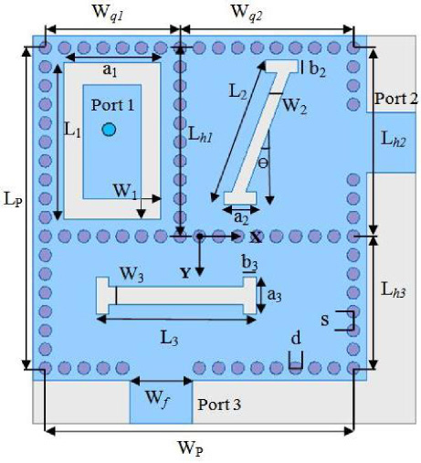
Geometrical structure of the proposed self-triplexing antenna.
The geometrical values of the proposed antenna
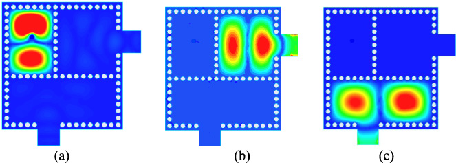
The proposed antenna structure depends on the integrated cavities technique; by this, the antenna uses the single-layer patch area in the form of different cavities (QM & HM) for multiband applications. For the rectangular SIW cavity, the dominant mode TE10 is attained at 8.3 GHz within X-band. After that, the inverted “T”-shaped metallic cavity is used to implement the two QM cavities and an HM cavity without the radiating slots. The proposed two QM cavities are not perfectly equal to each other; otherwise, the same dominant and higher-order modes are found. The propagating modes in a particular QM and HM cavity are realized using mathematical equations (1), (2), and (3), respectively [32,33]. When port 1 is ON, the dominating mode (TE110) and the higher-order mode (TE120) of QM cavity-1 are obtained at 7.14 GHz and 12.2 GHz. While port 2 and port 3 is excited simultaneously, the dominating mode (TE110) is found at 6.45 GHz and 9.65 GHz, and higher-order mode (TE210) is attained at 11.45 GHz and 12.6 GHz, respectively. These propagating modes are explained by the |Z|-parameters as display in Fig. 3, while the electric field distribution of the dominant and higher-order modes is displayed in Fig. 4 and Fig. 5 independently.

The |Z|-parameters of the inverted “T”-shaped cavity without slots.

The electric field distribution of dominant mode (TE110) in the proposed inverted “T”-shaped cavity: (a) QM cavity-1, (b) QM cavity-2, and (c) HM cavity.
The electric field distribution of higher order mode (TE120 and TE210) in the proposed inverted “T”-shaped cavity: (a) QM cavity-1, (b) QM cavity-2, and (c) HM cavity.
Dominant mode (TE110) of QM cavity 1 [32,33],
The two dumbbell-shaped slots of different lengths and widths, transversal to the excitation input ports, are etched in the QM cavity-2 and an HM cavity. A rectangular-shaped annular slot is engraved on the upper side of the QM cavity-1 and excited by the coaxial probe at the center of the slot from the X-axis and 1 mm away from the Y-axis. Here all of these slots are radiated into free space at the particular resonating frequencies.
When port 1 is ON, the QM cavity-1 is radiated through an annular slot, and the higher-order mode (TE120) at 12.2 GHz turns into the first resonating frequency at 9.37 GHz, while the other two ports become an idle and negligible fraction of the electric field is achieved simultaneously as shown in Fig. 6(a). The length of the slot 1 is longer (L 1 > L 2, L 3) than others; it offers a stronger loading effect and perturbs from 12.2 GHz to 9.37 GHz. When port 2 is active, the antenna is excited by an angular dumbbell-shaped slot within QM cavity-2. It produces the middle resonant frequency at 9.86 GHz by virtue of the average slot-loading effect, as displayed in Fig. 6(b). Here, the average perturbation of higher-order mode (TE210) takes place from 11.45 GHz to 9.86 GHz. Similarly, when port-3 is ON, and other remaining ports are inactive, higher-order mode (TE210) at 12.6 GHz converts into 10.36 GHz as the last resonating frequency; due to the etching of the slot over the HM cavity, as shown in Fig. 6(c). By realizing the proposed configuration, triple resonating bands are found with a good isolation value, which helps define the self-triplexing functionality.
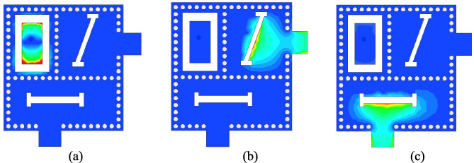
The electric field distribution of resonating mode in the proposed inverted “T”-shaped cavity: (a) QM cavity-1, (b) QM cavity-2, and (c) HM cavity.
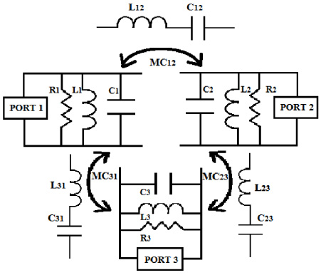
The equivalent circuit model of the proposed self-triplexer antenna.
The equivalent circuit model of the proposed self-triplexer is portrayed in Fig. 7; here, each resonating cavity is prototyped as three individual parallel RLC segments [34]. The parallel RLC circuit combination provides a filter network to either select the desired frequency or reject the others. At the resonant condition, the voltage and current are in phase and produce the maximum impedance at resonating frequency. So, that the parallel circuit is defined as the rejecter circuit; also. Here, each parallel RLC section is combined with an impedance (50Ω) matching terminal separately and generates the notch at three distinct resonating frequencies 9.37, 9.87, 10.36 GHz with reasonable isolation, respectively. The series combination of LC networks is known as a tuned circuit. It provides good selectivity or negligible interference from another channel. Initially, the capacitor is fully charged, and the electromotive force (EMF) develops across the inductor; based on the current flow in the circuit. This forms the endless oscillation of energy from one port to another and is also defined as an acceptor circuit. It gives the maximum current and minimum impedance at the resonating frequency. So, inter-mutual coupling among three ports is explained by a series combination of the LC network and denoted by MC12, MC23, and MC31 [35]. MC12 represents the mutual coupling between resonating cavity 1 and resonating cavity 2. The MC23 and MC31 is also the representation of mutual coupling between consecutive QM and HM resonating cavities.
This equivalent circuit prototype and lumped element values are realized by the Advanced Design System (ADS) software package. A comparison between simulated |S|-parameters by HFSS (high-frequency structural simulator) software and ADS is displayed in Fig. 8. A reasonable matching between two software results is obtained. The fair value of the reflection coefficient and isolation is achieved. The values of RLC and LC segments are given in Table 2. The resonating frequencies and the quality factor (Q-factor) are calculated by Eqs (4) and (5), respectively [36]. The bandwidth at the first resonant frequency (9.37 GHz) is minimum than others, while the bandwidth at the middle frequency (9.86 GHz) is maximum and average at the third resonating frequency (10.36 GHz). Likewise, Q-factor is leading at the first resonant frequency and minimum at middle frequency, which can be easily determined by Eq. (5).
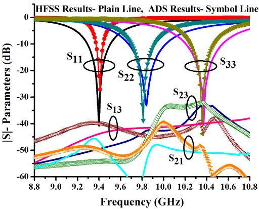
The comparison between |S|-parameters simulated by HFSS and ADS software.
Values of parallel RLC and series LC elements
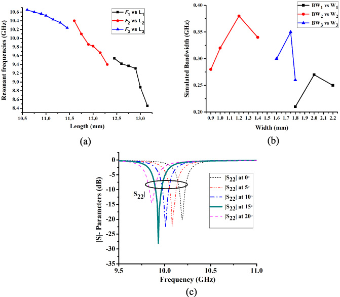
The variation in resonant frequencies with respect to (a) lengths of slot, (b) widths of slot, and (c) angles of slot-2.
The operating frequency can be determined by [36],
The effects of several parameters over the proposed triplexer are investigated with the HFSS electromagnetic software’s help. The deviations of operating frequencies (f 1, f 2, and f 3) with respect to the slot lengths (L 1, L 2, and L 3), slot width (w 1, w 2, and w 3), and slot angle (Θ) are explained in this section, along with the importance of an inverted “T”-shaped cavity. The variation in resonant frequency depends upon the slot lengths has an inversely proportional relation to each other, as shown in Fig. 9(a). The proposed antenna has the property of frequency tunability at all operating frequencies, which is more desirable and favorable from the RF designer’s perspective. As lengths of the slot (L 1, L 2, and L 3) increases by the results respective frequency becomes decreases. The first resonant frequency (f 1) can be tuned from 8.4 to 9.56 GHz by varying the slot length L 1 from 12.45 to 1315 mm. This frequency range can be used for the fixed-satellite (earth to space), earth exploration satellite (space to earth-uplink), and aeronautical radio-navigation purposes [31,37]. Similarly, the middle resonant frequency (f 2) can be tuned from 9.4–10.45 GHz by changing the slot length L 2 from 11.6–12.35 mm. This operating range can be used for radiolocation and amateur satellite links [37]. Likewise, if slot length L 3 varying from 10.6–11.45 mm, as a result, the last resonant frequency (f 3) can be tuned from 10.65–10.24 GHz and can be easily used for radio astronomy, earth exploration satellite (space to earth-downlink) applications. Due to its frequency tunability characteristic, the present antenna can also be suitable candidates for an X-band transmit-receive module for the wireless communication system operating in the range of 9.25 GHz to 10.75 GHz [38].

The isolation levels of the proposed antenna without an inverted “T”-shaped cavity.
The slot width generally helps to observe the bandwidth of the antenna. It can be noticed from Fig. 9(b), the maximum bandwidth is achieved at the particular value of slot width. Here, slot 2 and slot 3 are used as dumbbell-shaped, having a higher bandwidth than slot 1 [39,40]. Previously, the rectangular-shaped slots are used in the dumbbell slot; but the lower value of impedance bandwidth as 0.72%, 0.81% is found, respectively. Therefore, the dumbbell-shaped slots are preferred for the interest of enhanced bandwidth. Slot 2 is the angular dumbbell-shaped slot, and its performance concerning |S|-parameter is displayed by changing the angle (Θ) value from 0° to 20° and presented in Fig. 9(c). The maximum value of the reflection coefficient (S 22), i.e., good matching, is found at an angle of Θ = 15°. Therefore, Θ = 15° is selected for slot 2.
Previously, the proposed self-triplexer antenna is implemented without an inverted “T”-shaped cavity. As an outcome, a minimum value of isolation levels with reasonable gain (<4.5 dBi) and radiation efficiency (<78%) is obtained due to the electric field interference among the input ports. Figure 10 shows the maximum mutual coupling or minimum intrinsic isolation (>17 dB) levels among three input ports. An approach of cavity-backed self-triplexing antenna has the main feature of high isolation and maximum boresight gain; therefore, an inverted “T”-shaped cavity is introduced inside the SIW cavity. After implementing an inverted “T”-shaped cavity, the maximum amount of isolation and gain is achieved because of negligible interference of the electric field among consecutive cavities, as appear in Fig. 6(a,b,c).
The proposed antenna prototype is fabricated by milling machine using the single substrate layer of RT/Duroid 5880 with a dielectric constant (ϵ r ) of 2.2, thickness (h) of 1.57 mm, and loss tangent (tanδ) of 0.0009 as displayed in Fig. 11. The comparison between simulated and measured |S|-parameters are shown in Fig. 12 and determined by vector network analyzer (VNA) Agilent TN5247A. When port 1 is on, the antenna is excited at a measured frequency of 9.34 GHz with measured bandwidth (9.25–9.48 GHz) of 2.5%, while a 50Ω load matches other ports. Likewise, when the antenna is excited by port 2, other input ports are ended with a 50Ω matched load; the second measured frequency is obtained at 9.88 GHz. The measured impedance bandwidth (9.67–9.98 GHz) is 3.16%. Similarly, the third measured resonant frequency band exhibits the bandwidth (10.2–10.5 GHz) of 3% with the peak at 10.33 GHz; other ports are terminated by 50Ω load. The measured values of input port intrinsic isolations are higher than 31 dB and shown in Fig. 12, which is practically acceptable to visualize the self-triplexing property. Due to the separate cavity aperture, the interference is negligible; consequently, the maximum values of gain and radiation efficiency are achieved compared to the other triplexing antennas. The simulated gain values are 7.7 dBi, 7.53 dBi, and 6.58 dBi, while measured gain values are 6.67 dBi, 6.5 dBi, and 5.6 dBi at the first, middle, and upper-frequency band respectively, as displayed in Fig. 13(a). Figure 13(b) shows that simulated radiation efficiency values are greater than 95%, while measured radiation efficiency is 84%, 84.5%, and 83% at the first, middle, and upper bands independently. However, there is a slight deviation between the simulated and measured result outcomes due to fabrication tolerances and some uncontrolled dielectric and soldering losses.
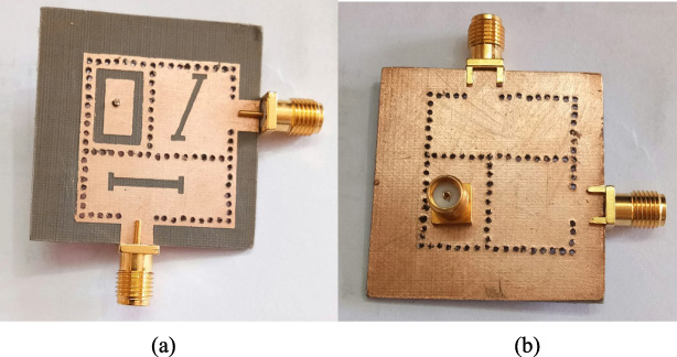
(a) The front, and (b) the back view of the proposed antenna.
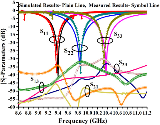
The simulated and measured |S|-parameters of the proposed antenna.
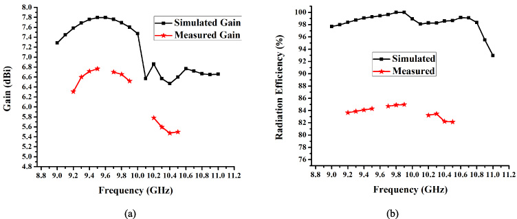
The simulated and measured (a) gain, (b) radiation efficiency of the proposed antenna.
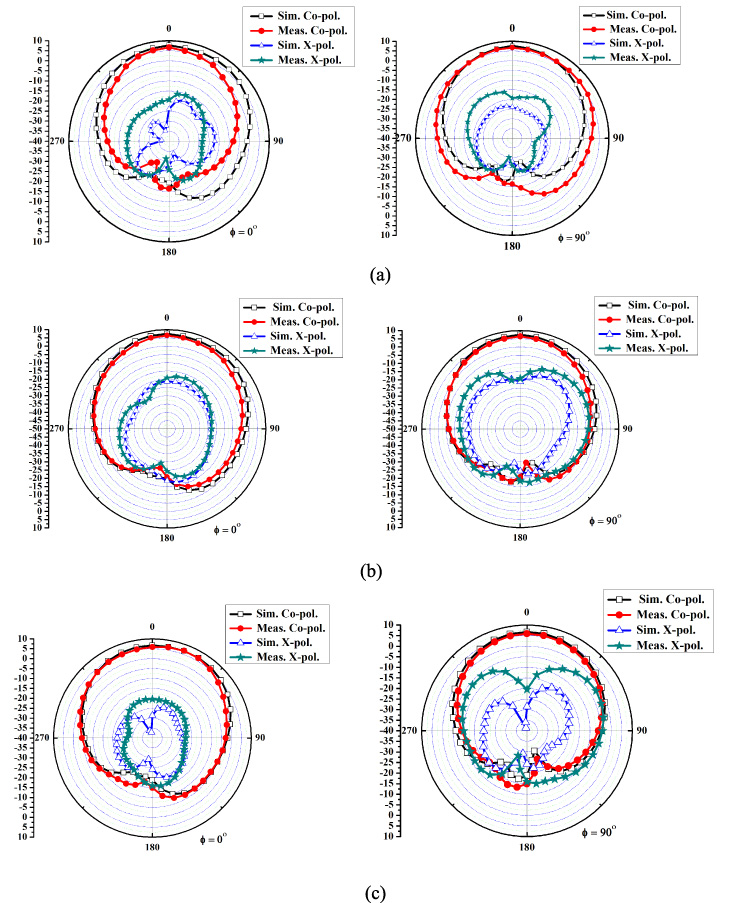
Radiation patterns: 𝜙 = 0°, and 𝜙 = 90° plane at (a) 9.37 GHz (port 1 ON), (b) 9.86 GHz (port 2 ON), (c) 10.36 GHz (port 3 ON).
An anechoic chamber setup is used to measure the far-field radiation characteristic of the proposed self-triplexing antenna. The simulated and measured radiation patterns (𝜙 = 0°, 𝜙 = 90°) at all three resonating frequencies shown in Fig. 14. Each radiation plot presents the uni-directional radiation pattern oriented towards boresight direction by virtue of the antenna’s cavity-backed functionality. The simulated front-to-back ratio (FTBR) is better than 23 dB, and measured FTBR is better than 20.5 dB. The simulated cross-polarization levels in boresight direction are −23 dB, −21.5 dB, and −28.7 dB and measured values are −20.2 dB, −19.1 dB, and −20.5 dB at three resonating frequency respectively. Table 3 shows the proposed antenna’s comparative results with the previously reported structures in terms of isolation, gain, bandwidth, etc.
Comparison of proposed antenna with previous reported literatures
FTBR - Front to back ratio; 𝜆 L is the lowest wavelength; N.A. - Not available.
This proposed research paper introduces a new structure of triplexing slot antenna for triple-band operations, materialized by SIW cavity. The structure arrangement is nested by two QM cavities and an HM cavity; combined with the individual radiated slots. These slots are excited through respective ports and produce reasonable intrinsic isolation among them. The prototype is fabricated to verify simulated results, and close agreement between measured and simulated results are found. The proposed structure (0.8𝜆 L × 0.75𝜆 L ) is more compact than previously published work with highly improved isolation levels and gain values. It is a suitable prototype for X-band wireless and radar communication systems.