
Abstract
This paper deals with development of in-wheel magnetic-geared motor for walking support machines. In a previous paper, a magnetic-geared motor for a walking support machine was prototyped. However, its efficiency was low, therefore improving the efficiency is necessary for practical use. This paper presents the improving efficiency of the magnetic-geared motor from the viewpoint of torque increasing and loss reducing by using a three-dimensional finite element method (3D-FEM). In addition, supporting method of pole-pieces and eddy current loss in housing were discussed. Furthermore, the proposed motor is prototyped. The experimental results show that its efficiency is 15% higher than the previous motor. Finally, the walking support machine installed with two magnetic-geared motors is prototyped and demonstrated.
Introduction
Magnetic gears have attracted attention since they can transmit mechanical power without any contacts using electromagnetic force. Hence, they can minimize vibration, wear and tear, which offers maintenance–free operation in contrast with mechanical gears Conventional magnetic gears have the similar structure as mechanical gears, hence the torque density is low because only permanent magnets facing each other contribute to transmit torque [1]. On the other hand, a flux-modulated type magnetic gear has recently attracted interest [2,3]. Its torque density is higher than conventional magnetic gears because all the magnets facing each other contribute to transmit torque. Furthermore, the operational principle is the same as permanent magnet (PM) motors, therefore they can combine magnetically and mechanically as a magnetic-geared motor [4,5]. Accordingly, it is expected to be reduced overall size and weight in comparison with conventional mechanical-geared motors. Moreover, the torque density is higher than direct drive type electric machines. Hence, the magnetic-geared motor is suitable for low speed and high torque applications; for example, electric vehicles, electric propulsion ships and so on.
In Japan, the declining birthrate and aging population have become a serious social problem, thus walking support machines which are driven by electric motors attracted attention since it is able to assist to go out for elderly people. However, it has a problem of large weight and small luggage space due to electric motors. To overcome this problem, the magnetic-geared motor is expected to be applied for the walking support machines. In an example of the magnetic-geared motor applied for vehicles, a 100 kW-class magnetic-geared motor was prototyped and applied to an electric vehicle as a traction motor in [6]. However, the magnetic-geared motor applying to a small vehicle like the walking support machine has not been reported.
In a previous paper, a magnetic-geared motor for walking support machines was prototyped. Although the target torque was achieved, the efficiency of the prototype motor is not enough high [7].
This paper deals with the improvement of the magnetic-geared motor for the walking support machine. Fast of all, it is discussed that improving efficiency of the magnetic-geared motor from the viewpoint of torque increasing and loss reducing by a three-dimensional finite element method (3D-FEM) using the JMAG-Designer software ver. 18.1. In addition, supporting method of pole-pieces and eddy current loss in housing are discussed. Furthermore, the proposed motor is prototyped and tested. Finally, the walking support machine installed with two magnetic-geared motors is prototyped and demonstrated.
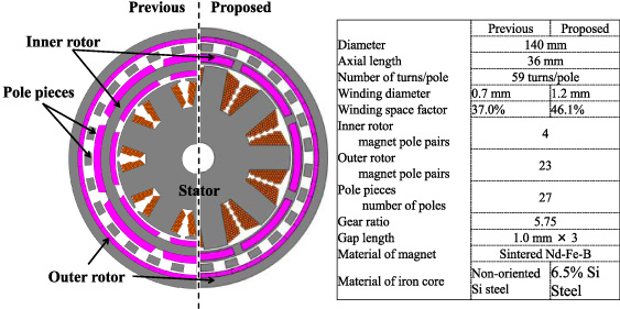
Specifications of the previous and the prototype magnetic-geared motors.
Specifications of the previous and the proposed magnetic-geared motors
Figure 1 shows specifications of the previous and the proposed magnetic-geared motors. As shown in the figure, a permanent magnet motor is magnetically and mechanically integrated into the inside of the magnetic gear and shared the inner rotor. The motor part is composed of a 9-slots stator with three-phase concentrated windings and the shared 4-pole-pairs inner rotor. The gear part is consisted of the shared 4-pole-pairs inner rotor, a 23-pole-pairs outer rotor, and a 27-pole-pieces stator. Hence, its mechanical output can be obtained from the outer rotor of which the speed is reduced by the gear ratio of 5.75 (= 23/4). As shown in the figure, the improvements of the proposed motor include a slot shape, an inner rotor structure, and core material based on the results described below.
Increasing torque and reducing loss
The efficiency of electric motors is obtained from dividing the output power by the input power. The output power is given by multiply an angular velocity and an output torque. The input power is calculated by adding the output power and total losses. Therefore, both increasing torque and reducing loss are necessary for the efficiency improvement at constant speed condition. In this section, methods for increasing torque and reducing loss are described. After that, torque, loss, and efficiency characteristics are indicated in order to prove the validity of the proposed methods.
Increasing torque and decreasing copper loss
The previous motor has low winding space factor because it has a semi-closed slot structure as shown in Fig. 1. To resolve the issue, an open slot structure was employed for the proposed motor. As a result, the winding space factor increased 9% in comparison with the previous motor, which is expected to improve not only the torque but also the copper loss since the winding diameter can be larger, that is, the winding resistance can be decreased.
However, the open slot structure causes large cogging torque and iron loss due to slot harmonics in general. Fast of all, the cogging torque is calculated by 3D-FEM. Figure 2(a) indicates a calculation result of the cogging torque waveform in each slot structure. It is understood that both cogging torques are almost the same because the slot combination of the both motor are 9-slots and 8-poles which is able to decrease the cogging torque.
Figure 2(b) shows calculated torque characteristics in the both motors. The figure reveals that the torque of the proposed motor is 1.7 times larger than that of the previous one at a current density of 6 A/mm2 because the winding space factor is improved due to employing the open slot structure. Figure 2(c) indicates the copper loss characteristics in the both motors. It is clear that the copper loss is remarkably reduced since the winding resistance is decreased by employing the larger winding diameter.
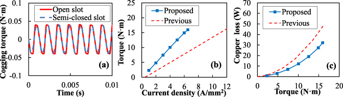
Calculated results of cogging torque, average torque, and copper loss.
The inner rotor in the previous motor is a surface permanent magnet (SPM) type as shown in Fig. 1. In SPM type, harmonic fluxes directly flow into the magnets, which causes eddy current loss and worse efficiency. Therefore, the inner rotor structure in the proposed motor is changed to an interior permanent magnet (IPM) type. In this type, the harmonic fluxes are prevented from flowing into the magnets due to the iron yoke.
A non-oriented Si steel is employed in the stator and the rotor core of the previous motor. This paper focuses on a 6.5% Si steel which has higher resistance and thinner thickness in comparison with the conventional non-oriented Si steel. Therefore, it is expected to reduce the iron loss. However, torque might be decreased since the saturation flux density is lower than that of the conventional Si steel. Thus, the torque characteristics in each core materials are compared. Figure 3(a) indicates the calculation result of torque in each core material. The figure shows that deterioration of torque is very slight.

Calculated result of eddy current loss in magnets, iron loss, and efficiency.
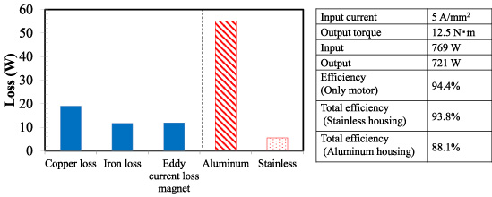
Figure 3(b) indicates comparison of the eddy current loss in magnets W e and the iron loss W i . The figure revels that both losses are reduced significantly, e.g., W e is 55% and W i is 66%, respectively at a load torque of 15 N ⋅ m. Hence, it is understood that W e is reduced by employing the IPM rotor, and W i is reduced by employing the 6.5% Si steel. Figure 3(c) indicates calculated efficiency. It is understood that the efficiency of the proposed motor is improved remarkably, and the maximum efficiency reaches to 94.4%.
Figure 4(a) illustrates a cross-sectional view of the prototyped motor and (b) shows a supporter of pole-pieces. In [7], it was reported that the pole-pieces were set in a latticed supporter made of synthetic resin however, it is difficult to fix the pole-pieces due to large electromagnetic force.
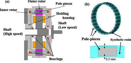
Cross-sectional view of the prototyped motor and a resin supporter of pole-pieces.
Calculation result of the eddy current loss in the housing.
To overcome this problem, the pole-pieces are embedded into the resin supporter as shown in Fig. 4(b) and the supporter is sandwiched between two holding housings as shown in Fig. 4(a), in order to obtain higher mechanical strength. In this paper, optimal material for the holding housings is also investigated since the magnetic-geared motor has three air gaps, thus leakage magnetic flux is affected to eddy current loss in the housing. Aluminum and stainless are generally used for the housing. Although aluminum has low cost and light weight, it has higher conductivity which is the cause of eddy current loss. On the other hand, stainless has low conductivity compared to aluminum although its cost is high. Thus, the eddy current loss in the housing is evaluated by 3D-FEM when a current density is 5 A/mm2.
Figure 5 indicates the comparison of the eddy current losses in the housing. The figure reveals the eddy current loss is about 55W in the case of aluminum, while about 5.5 W in stainless. Moreover, Fig. 5 shows the comparison of the efficiency in each housing material. It is understood that the total efficiency when using stainless is significantly higher than that using aluminum. Therefore, stainless is employed for housing material in the prototype motor.
Experimental results of the prototyped magnetic-geared motors
Based on the investigations described above, the proposed magnetic-geared motor was prototyped. Figure 6(a) shows the experimental setup. The inner rotor of which the position is detected by a hall sensor is controlled to 1000 rpm by current vector control. Then, the outer rotor speed is reduced to 174 rpm according to the gear ratio of 5.75.
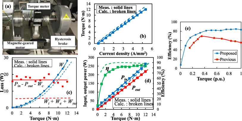
General view of the experimental setup and experimental results of the prototype magnetic-geared motor.
Figure 6(b) indicates the comparison of measured and calculated torque characteristics. It is understood that the measured torque is good agreement with the calculated one since both slopes are almost the same. Figure 6(c) shows the comparison of measured and calculated losses. The solid lines represent the measured losses, while the broken lines denote the calculated ones. In the figure, the copper loss is W c , the eddy current loss in the magnets is W e , the iron loss is W i , and the eddy current loss of the housing is W sus , respectively. It is understood that the sum of the calculated losses W i + W e + W sus are remarkably different from the measured loss which is obtained from P in (input power) - P out (output power) - W c , since the mechanical loss is ignored in 3D-FEM.
Figure 6(d) indicates the comparison of measured and calculated efficiency of the proposed machine, and Fig. 6(e) shows the comparison of measured efficiency of the previous and proposed machines. In the figure, the measured torque is normalized with the maximum torque because the axial length of the previous machine is 10 mm shorter than the proposed one. The figure reveals that the measured maximum efficiency reaches about 85% which is 15% higher than the previous magnetic-geared motor. The results demonstrate that the proposed methods for torque improvement and loss reduction are effective for improving the efficiency.
In the previous section, the efficiency improvement is demonstrated by the prototyped motor. Therefore, the walking support machine installed with two magnetic-geared motors is prototyped to prove the feasibility.
Figure 7(a) shows the control diagram of the prototyped walking support machine, which consists of the 24 V lead acid battery, the main controller (mbed LPC 1768), two inverters (NUCLEO-F303RE, X-NUCLEO-IHM08M1), and two magnetic-geared motors, respectively. The d-axis current of the magnetic-geared motor is controlled to zero. When the reference q-axis current is inputted by the controller, it is transferred to the main controller. After that the reference signal is sent two inverters by the main controller, the magnetic-geared motors are rotated according to q-axis current. Hence, the walking support machine is driven by two magnetic-geared motors.
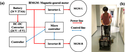
Control diagram of the prototyped walking support machine (a) and a picture of the running test (b).
Figure 7(b) shows a picture of the running test of the prototyped walking support machine. The prototyped machine is driven smoothly and assist the walking of a user.
This paper presented the efficiency improvement of the in-wheel magnetic-geared motor for walking support machines. Furthermore, the proposed magnetic-geared motor was prototyped and installed in the walking support machine.
Firstly, methods for increasing torque and reducing loss were studied by comparing to the previous motor. The torque was increased by employing the open slot structure since winding space factor is improved. The eddy current loss in magnets can be reduced by IPM-type inner rotor, and the iron loss is decreased by employing 6.5% Si steel. As a result, the calculated maximum efficiency without mechanical loss reached 94.4%. Next, the proposed magnetic-geared motor was prototyped and demonstrated. The measured torque was good agreement with the calculated one and the maximum efficiency reached about 85%, which is 15% higher than the previous motor. Therefore, it was proved that the proposed methods for torque improvement and loss reduction are effective for improving the efficiency. On the other hand, it was found that the mechanical loss should be reduced in order to further improve efficiency. Finally, the walking support machine installed with the magnetic-geared motors was prototyped and tested. It was demonstrated that the prototyped walking support machine was driven smoothly. Therefore, a magnetic-geared motor can be applied to walking support machines.
In the future study, the driving test of the walking support machine will carry out deeply; for example, continuous drive, measurement of the dynamic characteristics and so on.
Footnotes
Acknowledgements
This work was supported in part by the WISE Program for AI Electronics, Tohoku University.