
Abstract
We propose a magnetic-geared motor with controllable step-out torque. The operational principle which controls the step-out torque using DC currents is described. The controllable step-out torque characteristics are computed using finite element method. In addition, the load characteristics under vector control are also computed using finite element method. Two inherent characteristics are observed in this analysis result. One is that this magnetic-geared motor can generate the torque more than the step-out torque. The other is that the phase angle difference between the rotors when both rotors step out is around 30 deg. In this paper, the mechanism of these inherent characteristics is investigated by finite element method, and these inherent characteristics are verified by carrying out measurements on a prototype.
Introduction
A magnetic-geared motor is a low-speed and high-torque motor because a magnetic gear is installed. The magnetic-geared motor consists of high- and low-speed rotors, and stator, and has been developed for the application of a low-speed and high-torque motor such as an wind power generator. The high-speed rotor and stator have permanent magnets, and the assemblability of the magnetic-geared motor is low due to its configuration [1–8]. Reference [1] describes a vernier motor with permanent magnets in its rotor and stator. Reference [2] describes an outer rotor type vernier motor with permanent magnets sandwiched by rotor yokes. Reference [3] describes a magnetic-geared motor that Halbach array is applied to both rotors. Reference [4] describes a magnetic-geared motor with permanent magnets sandwiched by pole pieces of the low-speed rotor. Reference [5] describes a magnetic-geared motor with three-step-skewed permanent magnets only in its high-speed rotor. Reference [6] describes a magnetic-geared motor whose stator consists of pole pieces with two-step skew. Reference [7] describes a magnetic-geared motor with two rotors and two stators. Reference [8] describes a magnetic-geared motor with two stators. In this way, a variety of magnetic-geared motors are proposed. However, the assemblability of these motors are low.
In order to enhance the assemblability, a magnetic-geared motor with permanent magnets only in its high-speed rotor is proposed [9]. Furthermore, in order to enhance the assemblability more, we propose a magnetic-geared motor with permanent magnets only in its high-speed rotor as shown in [10]. However, the step-out torque is decreased because the permanent magnets in the stator are removed. In addition, we propose a magnetic-geared motor with permanent magnets only in its stator. The step-out torque is also decreased, where the step-out torque without DC currents is defined as 𝜏0. However, the magnetic-geared motor can control the step-out torque using DC currents, and can compensate the transmission torque decrease. Moreover, the magnetic-geared motor can output torque more than the step-out torque 𝜏0 [11].
In this paper, the mechanism of these inherent characteristics of the newly proposed magnetic-geared motor is investigated by finite element analysis (FEM). In addition, these inherent characteristics are verified by carrying out measurements on a prototype.

Proposed magnetic-geared motor.
Configuration of proposed model
Figure 1 shows the section draw of the proposed magnetic-geared motor, which consists of high- and low-speed rotors, and stator. The outer diameter of the stator is 𝜙125 mm, and the stack length is 50 mm. The number of salient poles in the high-speed rotor is 10, that of pole pieces in the low-speed rotor is 22, and that of stator teeth is 12, where the pole pieces are made of laminated silicon steel sheets, and are molded by epoxy resin. The high-speed rotor and stator are made of laminated silicon steel sheets, and the stator has 2 sets of 3-phase coils, where the number of coil turns is 90. NdFeB permanent magnets (N42SH) are arranged only in the stator. Therefore, the step-out torque is lower than a conventional magnetic-geared motor that have permanent magnets in its high-speed rotor and stator. However, in the proposed model, DC currents can control the step-out torque.
The proposed magnetic-geared motor has 2 sets of 3-phase coils because the positive and negative DC currents must be cancelled with each other, where the DC current controls the magnetic flux due to the permanent magnet, and the AC current generates the rotating magnetic field [12]. A 3-phase vector control can rotate the magnetic-geared motor. In addition, the step-out torque can be increased by superimposing DC current on a 3-phase AC current, where positive DC currents are applied to one set of 3-phase coils, and negative DC currents are applied to the other set of 3-phase coils. In this way, the magnetic-geared motor can be driven with and without DC currents.
Step-out torque
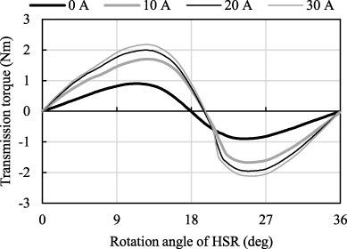
In order to verify the controllable step-out torque characteristics, 2-D FEM is conducted using JMAG-Designer (JSOL) in the proposed model. Figure 2 shows the transmission torque waveforms that the DC current is changed from 0 to 40 A. From Fig. 2, it is observed that the step-out torque under 40 A is twice as large as that under 0 A. The increase ratio of the step-out torque decreases as the DC currents increase. This is due to the magnetic saturation in the stator.

Computed transmission torque waveforms.
FEM analysis information
In order to investigate the characteristics under load, the load characteristics without DC currents are investigated by a coupled analysis of JMAG-Designer and Matlab/Simulink. The number of elements in the FEM analysis is about 30,000, the number of steps is 1,000, and the calculation time is around 20 minutes. Table 1 shows the specification of the computer used for the FEM analysis. Figure 3 shows the relationship between the load and phase angle difference between rotors when a load increases by every 0.25 Nm, where any DC currents are not applied. From Fig. 3, we can see that the magnetic-geared motor outputs a torque larger than the step-put torque 𝜏0 shown in Fig. 2. It can be guessed that the step-out torque is between 1.5 and 1.75 Nm because both rotors step out under a load of 1.75 Nm. In this time, the phase angle difference between rotors is around 40 deg although the step-out torque of a conventional magnetic-geared motor is around 90 deg.

Relationship load and phase angle difference between rotors without DC currents.
Next, the load characteristics with DC currents are investigated. Figure 4 shows the relationship between the load and phase angle difference between rotors when a load increases by every 0.25 Nm. From Fig. 4, we can see that the phase angle difference is around 45 deg under a load of 3.75 Nm. Focusing on the characteristics under 3.0 Nm, the phase angle difference is 35 deg, and the DC current is 30 A.
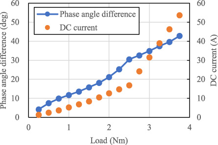
Relationship load and phase angle difference with DC currents.
On the other hand, from the torque waveform in Fig. 2, the phase angle difference is around 90 deg when the transmission torque is 3.0 Nm under a DC current of 30 A. From this, it is observed that the magnetic-geared motor can also output torque more than the step-out torque 𝜏0 when DC currents are applied.
Finally, the mechanism that both rotors step out at a phase angle difference of around 40 deg is described. The AC currents generate torque on the low-speed rotor as well as the high-speed rotor because the modulated flux in the outer air gap couples with the rotating magnetic flux due to the AC currents. In this time, the phase angle difference between rotors is equal to the leading angle of the phase current against the low-speed rotor because the AC currents are applied according to the high-speed rotor position. In this way, the output torque of the proposed magnetic-geared motor is the summation of the gear torque and current torque on the low-speed rotor. Figure 5 shows the relationship between the phase angle difference and the low-speed rotor torque when 6.4-Arms AC currents are applied, where the total torque is the summation of the current torque and transmission torque (gear torque) that is shown in Fig. 2, and the output torque is a computed output torque by FEM. From Fig. 5, it is observed that the phase angle difference when the low-speed rotor torque is 1.5 Nm is around 30 deg, and this shows a good agreement with Fig. 3. Therefore, the mechanism that the magnetic-geared motor outputs torque more than the step-out torque 𝜏0 is due to the current torque on the low-speed rotor that is almost the same level with the gear torque.

Relationship phase angle difference and low-speed rotor torque and its allocation.
Step-out torque
In order to verify the inherent characteristics of the proposed magnetic-geared motor, measurements on a prototype are carried out. Figure 6 shows the measurement setup for the transmission torque measurement, where the low-speed rotor is fixed by the hysteresis brake, and the high-speed rotor is rotated by the servo motor at 1 rpm. First, Fig. 7 shows the transmission torque waveforms, and Fig. 8 shows the measured relationship between the DC current and step-out torque. The measured step-out torque is about 30% lower than the computed step-out torque shown in Fig. 2. This is thought to be because the outer air gap length of the prototype is larger than that of the FEM model due to the large tolerance of the permanent magnet.
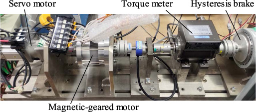
Measurement setup for transmission torque measurement.
Measured transmission torque waveforms.

Relationship DC current and step-out torque.

Measurement setup for phase angle difference measurement.
Torque and phase angle difference when AC current is increased.
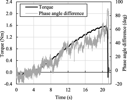
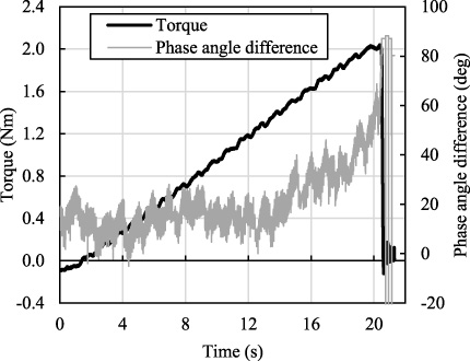
Figure 9 shows the measurement setup for the phase angle difference measurement, where two encoders are used. One encoder measures the high-speed rotor position, and the other encoder measures the low-speed rotor position. The phase angle difference between the rotors is calculated from these positions. The servo motor is connected with the low-speed rotor, and is rotated at 60 rpm. The relationship between the phase angle difference and torque when the AC current is increased is measured. Figure 10 shows the relationship between the phase angle difference and torque when the DC current is 0 A. From Fig. 10, the magnetic-geared motor steps out when the phase angle difference is around 60 deg, and the step-out torque is 1.6 Nm. From this result, it is found that the magnetic-geared motor can output torque more than 𝜏0, where the effective value of the current is 8 Arms. The measured phase angle difference when stepping out is 20 deg higher than the computed phase angle difference shown in Fig. 5. This is because the phase angle difference is sensitive to the torque around the phase angle difference when stepping out as shown in Fig. 5.
Figure 11 shows the relationship between the phase angle difference and torque when the DC current is 15 A. From Fig. 11, the magnetic-geared motor steps out when the phase angle difference is around 60 deg, and the step-out torque is 2.0 Nm. From this result, it is found that the magnetic-geared motor can output torque more than 𝜏0. In this way, the measurements verifies that this magnetic-geared motor can output torque more than 𝜏0, and the phase angle difference when stepping out is less than 90 deg.
Torque and phase angle difference when AC current is increased under DC current.

Torque and AC current waveforms without DC current.
Torque and AC current waveforms with a DC current of 10 A.
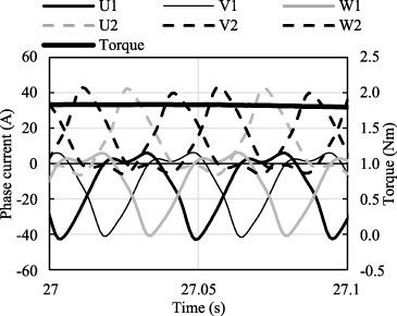
Furthermore, Figs 12 and 13 show the torque and current waveforms when the DC current is 0 A and 10 A, respectively. The DC current can be observed in the current waveforms only in Fig. 13. On the other hand, from Fig. 13, it is found that the current waveforms are not sinusoidal. This is because 3-phase vector control is applied to the composite 3-phase current of the same phases. For example, 3-phase vector control is applied to the composite current of the U1 and U2 phases shown in Fig. 1, and the inductance of the U1 and U2 phases are different from each other. Therefore, large harmonics are appeared in the current waveforms as shown in Fig. 13. From Fig. 13, the average value of the phase current is 10 A. In other words, the DC current can be controlled to 10 A although the harmonics are included in the phase current.
In this paper, the inherent characteristics of a magnetic-geared motor with permanent magnets only in its stator were investigated. The magnetic-geared motor could control the step-out torque using DC currents, and could output torque more than the step-out torque 𝜏0 thanks to the current torque of the low-speed rotor. These inherent characteristics were clearly investigated by finite element method. A measurement method for the phase angle difference between both rotors using two encoders was proposed, and these inherent characteristics were verified by carrying out measurements on a prototype. The measured phase angle difference showed a good agreement with the calculated phase angle difference. This mechanism is effective for the design of a magnetic-geared motor with permanent magnets only in the stator.
Footnotes
Acknowledgement
The authors have no acknowledgments.