
Abstract
It is always a challenge to quickly and effectively inspect the embedment depth of highway guardrail posts. This paper focuses on an electromagnetic ultrasonic transducer (EMAT) array that can excites torsional mode (T-mode) guided waves and applies it to check the embedment depth of guardrail posts. First of all, we presented a torsional guided wave EMAT array that can be used to quickly inspect the embedment depth of guardrail posts. The working principle of the EMAT array was described in detail. Secondly, a torsional guided wave EMAT array composed of 12 racetrack coils and 24 permanent magnets was simulated to verify the excitation and propagation process of torsional guided wave in a post. Then, a method for detecting the embedment depth of a post using the travel time of a torsional guided wave in the post was put forward. Finally, an experimental system was set up to carry out embedment depth detection experiments on posts with different depths buried in soil and concrete. Experiments have verified the feasibility of using the torsional guided wave EMAT array to inspect the embedment depth of the guardrail post.
Keywords
Introduction
The typical function of a roadside safety barrier includes preventing vehicles from falling off the road or hitting hazardous objects [1]. Highway guardrail, also called as “the last safety belt for protecting the driver’s life”, can protect vehicles from roadside hazards by redirecting errant vehicles in a safe manner as well as providing high levels of safety during and after impact [2]. However, the embedment depth of posts may not conform to the design criteria due to various reasons; meanwhile, the aging posts also become shorter or thinner because of corrosion, which leads to deterioration of mechanical properties. Therefore, it is necessary to inspect the embedment depth of guardrail posts on a regular basis. The traditional methods for inspection of embedment depth of a post mainly include pull-out testing method and impact elastic wave method [3]. The pull-out testing method is time-consuming and laborious, which is difficult to meet the needs of large-number inspection due to the problems of subgrade damage and secondary embedding. The impact elastic wave method, using impact elastic waves, can be performed on a non-destructive basis. However, the impact elastic wave is greatly interfered by the surrounding medium as it propagates along the post axis direction, which results in severe mode overlapping attenuation [4,5]. These disadvantages make impact elastic wave method difficult to apply in engineering practice.
Fortunately, the guided wave detection technology provides a realizable way for the inspection of the embedment depth of the guardrail post. There are three kinds of guided waves in the pipeline, i.e., longitudinal, flexural and torsional modes. Longitudinal and flexural waves have dispersive characteristics, which produces mode couplings and drag tails as travel distance increases, so they are not suitable for long-distance detection. On the other hand, the zeroth order torsional wave is non-dispersive, so the shape of the wave packets can be kept unchanged in propagation. By virtue of this characteristic, torsional waves have the great potential for inspecting the embedment depth of guardrail posts. First of all, it is necessary to know how to properly excite the torsional waves in the posts.
The traditional way to excite torsional waves in a column is to use piezoelectric probes [6–9]. However, the piezoelectric transducers often excite additional wave modes at the same time. Furthermore, the couplants needed between the transducer and specimen make it inconvenient to apply in engineering practice. In recent years, the magnetostrictive mechanism is widely studied and applied to excite torsional waves in columns [10–14]. In most cases, magnetostrictive transducers contain metal patches with high magnetostrictive properties and work in two steps. First, shear horizontal (SH) waves are generated in the metal patches by magnetostrictive forces. Then, the SH waves are coupled into the column by adhesive forces to form torsional waves in the columns. Therefore, this kind of transducer is also known as magnetostrictive patch transducer (MPT). The MPT requires magnetostrictive patches to be bonded to the columns, thus it is not suitable to moving and rapid measurements of post embedment depths.
In order to meet the inspection requirements of guardrail post embedment depth in this paper, an EMAT array based on the Lorentz force principle is proposed to excite the torsional wave in the post, and the effectiveness of its application to inspect the embedment depth of the post is validated. First, an EMAT array based on Lorentz principle is designed and the excitation of T-mode guided waves by the EMAT array is simulated by finite element method. Then, a method that uses the guided wave technology to inspect the embedment depth of the guardrail post is presented. Finally, an experimental setup of the guided wave testing system is introduced, and the embedment depth inspections of the guardrail post with different depths in soil and concrete are carried out. The factors that cause measurement errors and the methods to reduce them are also discussed.
Guided waves in hollow cylinder
The general theory of guided wave propagation in hollow cylinders can be refer to literatures [15,16]. The governing Navier’s equation for guided waves in an elastic medium is written as:
By adopting Helmholtz decomposition principle, as well as separation of variable technique, the displacement components can be expressed as:
Substitution of Eq. (2) into Eq. (1) leads to a characteristic equation, the dispersion curve can be obtained from the characteristic equation. The group velocity dispersion curves for a steel hollow cylinder can be seen in Fig. 1. There are three types of guided waves in the free pipe: longitudinal (L-), flexural (F-) and torsional (T-) modes. T(0, 1) mode is selected in this study because it is non-dispersive, and has lower attenuation and with constant phase/group velocity. T(0, 1) mode therefore is more preferred than longitudinal and flexural wave modes in long-range piping inspection [17,18]. As can be seen from the dispersion curves in Fig. 1, the group velocity of T(0, 1) mode guided wave keeps constant throughout the frequency range. This feature is very useful for measuring the length of waveguide structure. Therefore, in this work, we use T(0, 1) mode guided wave to detect the embedment depth of the post.
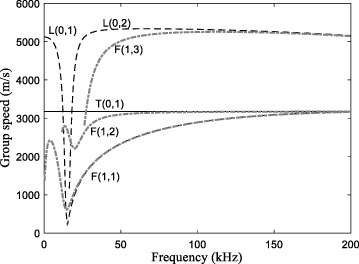
Group velocity dispersion curves of longitudinal, torsional and flexural modes in hollow cylinder with outer diameter and inner diameter being 114 mm and 105 mm, respectively. The representation of L(0, n) denotes the longitudinal mode of the nth order, T(0, n) the torsional mode of the nth order, F(0, n) the flexural mode of the nth order.
In order to excite the torsional guided wave conveniently and quickly in the post, we propose a ring array structure of electromagnetic acoustic transducer based on the principle of Lorentz force. The EMAT ring array is placed along the circumference direction of the post to generate uniform circumferential forces for exciting torsional guided waves. The EMAT ring array is composed of 12 ordinary racetrack coil SH-wave EMATs, which are equally spaced around the column, and its cross-section is shown in Fig. 2 (a). Each SH-wave EMAT consists of one racetrack coil and two magnets, and these coils are series connected and will be driven at the same time. The poles of adjacent magnets are opposite, so that the Lorentz forces generated under the adjacent coils are in the same direction, as shown in Fig. 2(b). EMATs for the receiver are set in the same manner as that for the transmitter.

Layout of the EMAT ring array. (a) is a cross section of the EMAT ring array. (b) EMATs are connected in series to form the array.

Torsional guided wave generated in the post. (a) is the excitation force distribution in a cross section at a given time and (b) is the wave structure in radical position.
The commercial finite element software COMSOL Multiphysics is used to simulate the generation of torsional guided wave by the EMAT ring array. The Magnetic Fields module is used to generate the static bias magnetic field. A tone burst current is fed to the coils in another Magnetic Fields module. The Lorentz force is loaded in the post in Solid Mechanics module. After solution, the body load generated in the post varies with the alternating eddy current, and the excited torsional guided wave propagates along the axis of the post. As shown in Fig. 3, the distribution of the Lorentz forces are along the circumferential direction of the post, and the wave structure profile shows significant in-circumference displacement. These characteristics are consistent with that of T(0, 1) mode. So it can be confirmed that the proposed EMAT ring array excites only T(0, 1) mode guided wave.
Experiment setup
The guided wave test system consists of two EMAT ring arrays for transmitting and receiving guided waves, a 1.2-metre long post, a RITEC RPR-4000 high power amplifier and receiving pre-amplifier, an impedance matching network, an oscilloscope MDO3024 and a function generator DG4202. Each EMAT ring array for transmitter and receiver separately consists of 12 ordinary racetrack coil SH-wave EMATs. The racetrack coils of transmitter and receiver are connected in series. The magnetic field of each magnet is normal to the outer surface of the post. Neighboring magnets have opposite poles, and the magnets are put on the coils with edge lengths of 10 mm. The widths of coils are 8 mm. Two half-ring skeletons made with a 3D printer are used to hold the coils and magnets. The two half-ring skeletons are connected by hinge and can be quickly installed on the post under inspection. In addition, a bucket filled with soil is used in the experiment to bury the post.
The cosine signal modulated by the Hanning window is used as the high voltage pulse excitation signal of the EMAT coil. The central frequency f of the excitation signal can be determined by the dispersion curve of the torsional guided wave. The excitation frequency of guided wave has a significant influence on the propagation distance, the higher the excitation frequency of guided wave, the faster its attenuation [17]. In order to reduce its attenuation in detection, the excitation frequency used in this paper is 60 kHz. The transmitter is leveled with the free end of the post, so that the reflected echoes from the free end in the measurement of embedment depth can be avoided.
Embedment depth inspection
The schematic of the embedded depth inspection for guardrail post can be seen in Fig. 4, with the guardrail post embedded in the soil. A transducer is used to generate guided wave and a receiver is used for pitching up signals. The transducer is placed at the top of the post, while the receiver is located at the middle. The distance between the receiver and soil surface is L1. If the velocity of the guided wave is a constant, the embedded depth L of the post can be calculated as:
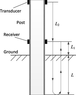
Schematic illustration of the embedment depth inspection of a guardrail post.
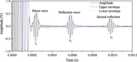
The collected signal. The dash lines are the envelope curves. t1, t2 and t3 are the time of direct wave packet, reflected wave packet and the second reflected wave packet, respectively.
The group velocity of the torsional guided wave propagation in the pipe used in this experiment is shown in Fig. 1. First-order torsional mode T(0, 1) group velocity is 3177 m/s. The receiver is installed at the middle of the post, 550 mm above the embedded end. The distance between the receiver and the ground is measured by band tape. The guided wave excited by the transmitter propagates in the axial direction and is reflected at the embedded end of the post. The propagation paths of the wave are illustrated in Fig. 4. The times of wave packets coming at the receiver directly and that reflected at the embedded end are measured by this system and no other unexpected wave is found between them. So the time of flight (TOF) can be calculated conveniently. However, it is difficult to accurately measure the arrival time of wave packets. The Hilbert-Huang transform (HHT) is used to solve the envelope of the signal. Travel time is obtained by calculating the TOF of direct and reflected envelope of wave packets as shown in Fig. 5.
Results and discussion
The generation and detection of T(0, 1) mode guided waves by the proposed EMAT is experimentally evaluated on the guardrail post. Firstly, we tested the post specimen with the embedment depths of 0 mm, 60 mm, 120 mm, 200 mm, 270 mm and 330 mm in the soil. Then, we also checked the posts buried in the soil with concrete covered, for which the total embedding depth (soil depth plus concrete depth) are 380 mm and 430 mm. The test was performed two days after concrete is poured. The embedded depth of guardrail post is calculated by Eq. (1). The testing results are listed in Table 1. One can observe the traveling time is almost a constant for all the embedment depths. The experimental results indicate that the maximum absolute error is 6.7 mm and the minimum is 0.4 mm. The maximum relative error is 3.35% and the minimum is 0.12%. The cause of the slight error of depths measurement is due to be peak values of envelope after Hilbert Transform. The peak values of the upper envelope and the lower envelope are not at the same time. As shown in Fig. 5, the TOF for upper envelope and lower envelope are 0.344 ms and 0.346 ms, respectively. In this work, the upper envelope is used to calculate the TOF. In addition, the sampling rate of oscilloscope also has some influence on the measurement error. In this experiment, the minimum sampling scale of the used oscilloscope is 2 μs. If the sampling rate of the oscilloscope is increased, the result will be more accurate.
It can be seen from Table 1 that the measurement results are always slightly less than the actual value. This should be caused by the fact that the group velocity used in the measurement is less than that of the guided wave in the actual post. In order to make the measurement results more accurate, the second reflection wave packet is introduced to calculate the wave velocity, as shown in Fig. 5. Since the second reflection wave packet reflected from the top end L2 in Fig. 4 can be easily measured, the group velocity of the torsional wave is calculated by v
g
= 2L2∕(t3 -- t2) Therefore, the embedment depth of the guardrail post can be calculated in a more effective way. So Eq. ((3)) for the post embedment depth is rewritten as
According to Eq. (4), the results of the embedment depth are inspected, shown in Table 1. From Table 1, we can see that the calculation results are more accurate and the errors are much reduced.
The inspection results of guardrail post embedment depth
In Fig. 5, the embedded depth is 430 mm, the amplitude attenuation of the reflection wave and the second reflection are 13.8 dB and 6.4 dB, respectively. The torsional wave has no dispersion and no mode overlapping, and its wave packets are independent and clear. Therefore, in practical application, the arrival time of the reflection wave can be accurately measured even without complex signal processing. It can be inferred that the T-mode guided wave can be applied to the embedded depth inspection of the guardrail post, and have the potential to nondestructive testing of the pipe-like structure that buried in the soil. It is expected that the guided wave testing system will lead to easy implementation in engineering. The more convenient guided wave testing system is under study in the near future.
Footnotes
Acknowledgements
This work was partly supported by Guangxi Key Laboratory of Manufacturing System and Advanced Manufacturing Technology (Grant Nos. 17-259-05-005Z, 17-259-05-007Z), National Natural Science Foundation of China (Nos. 11611530686), the State Key Laboratory of Mechanics and Control of Mechanical Structures at NUAA (No. MCMS-E-0520K02), and the Key Laboratory of Impact and Safety Engineering, Ministry of Education at Ningbo University (No. CJ201904).