
Abstract
This paper presents the performance of open-winding permanent magnet synchronous motor (OW-PMSM). It mainly includes vector modulation technology considering the unity power factor control.And a topology structure is proposed to optimize the fault tolerance of inverter. Matlab software and Maxwell software collaborative simulation are supplied to obtain the reactive power, speed, terminal voltage, electromagnetic torque etc. under normal and fault status. Finally, the simulation results of an open-winding permanent magnet synchronous motor are verified by the experimental results.
Introduction
OW-PMSM system opens the neutral point of the motor stator and connects a DC-to-AC converter in series, making the stator winding to supply power at both ends by two inverters. The first inverter provides the active power required for the normal operation of the motor. The second inverter provides reactive power for the motor by capacitor [1]. The advantage of the open-winding system is that the operating performance of the motor is significantly improved and the unit power factor operation of the main inverter is realized on the premise of the motor electromagnetic design and structure unbroken [2–4].
The composition of the OW-PMSM system is shown in Fig. 1. Inverter 1 provides active power required for the motor and Inverter 2 compensates the reactive power required by motor [5,6]. The compensating inverter 2 uses capacitor instead of power supply to supply the reactive power needed by the motor, and the capacitor coupled circuit suppresses zero sequence current, which also saves cost and the system is stable. Therefore, this paper used capacitor to supply power to the compensated inverter. Through the strategy proposed in this paper the DC link voltage increases and the maximum speed of motor is extended.
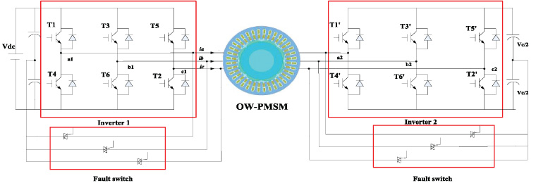
OW-PMSM drive system.
This paper focuses on the normal operation of the motor. The normal operation of motor can be divided into two states: constant torque operation and constant power operation. In constant torque region, maximum torque per ampere (MTPA) is taken to control system. In the flux weakening region, the traditional feedback flux weakening control is adopted. By optimizing the phase relation of voltage and current, a new open winding machine control scheme is proposed in this paper. The operation efficiency of the open winding is improved through perfection. And the fault-switch fault-tolerant control is used to ensure the steady operation of the motor. Finally, simulation and experiment verifies the feasibility of the strategy.
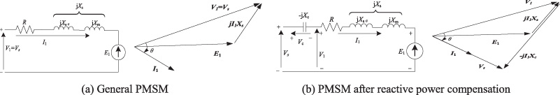
Stator equivalent circuit and steady state vector diagram.
In Fig. 2(a), a PMSM equivalent circuit and a phasor diagram for the motor equivalent circuit are shown. The PMSM equivalent circuit includes stator resistance R, stator leakage reactance jXsσ, excitation reactance jXm and the induced electromotive force E1. In order to better analyze the running state of the motor, the resistance voltage drop caused by the stator resistance R is ignored. The power supply Vs is composed of reactive voltage jI1Xs and induced electromotive force E1. The phase difference between Vs and I1 means that the power supply provides both the reactive power and active power required by the motor, resulting in low utilization of the power supply.
Figure 2(b) shows the equivalent circuit of the motor after adding reactive power compensation. The reactive power provided by jI1X1 and the reactive components of E1 is equivalent compensated by a series of equivalent capacitors Xc to make the power supply Vs unit power factor run. The jI1Xc provided by the capacitor compensates the reactive power of the motor without affecting the motor itself. As can be seen from the equivalent figure, Vs is less than V1, which means that the motor of the compensation strategy uses a smaller power supply to achieve normal operation.
In order to make the inverter 1 work in the state of maximum power factor, proposed the block diagram of control strategy as shown in Fig. 3.
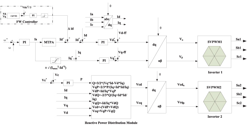
Block diagram of the proposed control strategy.
In Fig. 3, the d-axis and q-axis current references are generated by maximum torque per ampere (MTPA) strategy. The error between the given speed ω and the feed-back speed ω∗ is adjusted by PI to get the current Is. The motor voltage vector Vd, Vq is obtained by using conventional position feedback with an encoder. The connection between the constant torque and constant power region is realized by comparing the voltage Vd, Vq with the bus voltage Vdc. After PI adjustment, the voltage
The reactive power of the motor can be obtained according to the running state of the motor, as follows:
The real power flow to the inverter 2 is controlled to regulate the bridge capacitor voltage using an error signal and a PI controller:
Capacitors provide a small amount of active and most reactive power in an open winding system. Vcd and Vcq are components of capacitor voltage on d-q axis. Then decompose Vcd and Vcq into the form of active and reactive voltage provided on dq axis:
When calculating the active power provided by the capacitor, consider the capacitor as a resistance, and the active voltage on the dq axis is the same as the stator current phase, it can be deduced that:
When calculating the reactive power provided by the capacitor, take the capacitor as an ideal capacitor, and the capacitor voltage lags the motor current by 90 degrees.
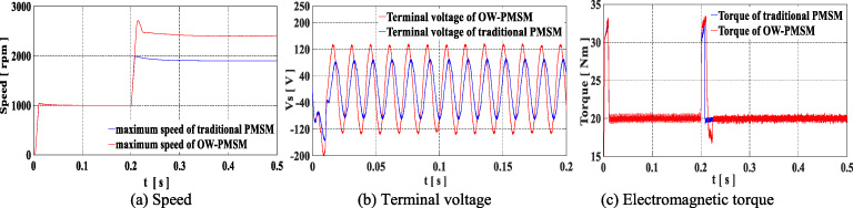
Table 1 shows the basic parameters of OW-PMSM. Figure 4 shows the comparison of traditional PMSM and OW-PMSM. As shown in the Fig. 4, the motor terminal voltage increased by 43.3% and the maximum speed extended by 26.3%.
The basic parameters of OW-PMSM
The basic parameters of OW-PMSM
Comparison of traditional PMSM and OW-PMSM.
Since the motor terminal voltage is synthesized by the output voltage of inverters on both sides, the motor terminal voltage can break the maximum voltage limit reached by the single inverter when the output of the main inverter is constant. The degree of voltage increase is related to the power factor of the motor. The lower the power factor, the greater the voltage amplitude increase and the greater the motor’s operating range expansion.
As the PMSM drive system in this paper is different from the traditional PMSM drive system of three-phase six-switch inverter, the stator current flows into the DC capacitance midpoint, which leads to periodic fluctuation of capacitor voltage and imbalance of stator current, and also increases torque pulsation. As shown in the Fig. 4(c), torque pulsation of the open-winding motor in the low-speed zone is larger than in the high-speed zone.
Figure 5 is the joint simulation of OW-PMSM based on control strategy. And the magnetic field of stator yoke increases due to the increase of voltage. Figure 6 shows the reactive power Q of OW-PMSM under different speeds.

Magnetic flux density distribution of OW-PMSM.
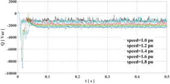
Reactive power Q at different speeds.
As shown in Fig. 6, the higher the motor speed under this strategy, the more stable the compensation intermediate variable Q is, and the better the compensation effect is. Under the support of the capacitor of one side inverter, reactive power can be output for compensation. Through side converter control capacitor compensating reactive power needed for the motor speed, make the output voltage of the DC power supply for the most part or all of the used for output active power, thus greatly improve the power density, increase output torque at low speed, high output power, so as to solve the single insufficient voltage converter motor speed limited. But this topology inevitably increases the hardware cost and control system complexity. The problem of power electronic device loss and electromagnetic compatibility caused by multi-inverter can’t be ignored.
In addition, power electronic devices are prone to failure due to high loss, high temperature rise and other problems. Fault tolerant switch is used to switch and disconnect the fault bridge arm during operation, and the motor continues to run in the original state.
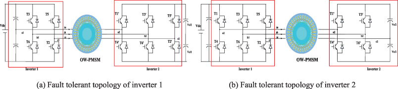
Fault tolerant topology of motor after inverter failure.
Figure 7(a) is the fault tolerant topology of inverter 1. When four switches are used to replace the main inverter, capacitors replace T1 and T4 bridge arms, and the main inverter 1 forms a three-phase four-switch topology. At the same time, the main inverter control strategy is switched to three-phase four-switch SVPWM control strategy.
Since the capacitor needs to be charged and discharged to form the bridge arm instead of the power supply, and the amplitude of the capacitor is easily changed by the change of the motor state, the time required for the initial start of the motor is relatively prolonged, and the overshoot of the speed is large. When the topology reaches the maximum speed of expansion, it is limited by the capacity of capacitor power supply, the switching time increases, the overshoot increases, and the motor runs stably after the capacitor charge and discharge is stable.
Figure 7(b) is the fault tolerant topology of inverter 2. When replacing secondary inverter 2 with four switches, capacitance replaces T5’, T2’. The secondary inverter is mainly responsible for compensation function, and the capacitance is prone to fluctuation due to motor state fluctuation. The compensation effect of the open-winding system is poor at low speed, and the periodic fluctuation of the capacitor compensation is large, which leads to the voltage pulsation of the capacitor and the increase of torque pulsation at low speed. The compensation effect is effective in high-speed zone, the inverter compensation capacity is stable, the torque ripple is basically eliminated.
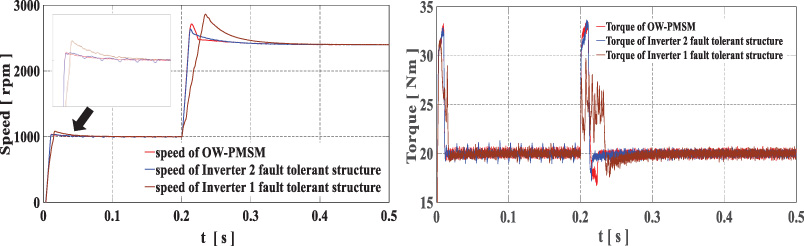
Speed and torque comparison of OW-PMSM fault tolerant system.
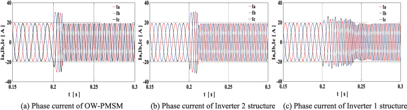
Phase current comparison of OW-PMSM fault tolerant system.
In Figs 8 and 9, the fault-tolerant system proposed in this paper can realize the normal operation of the open winding motor, has good robustness, and can make the open winding system low-cost.
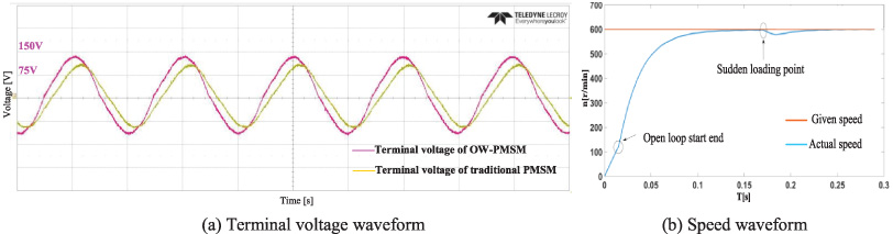
The OW-PMSM experimental system is conducted to verify the effectiveness of simulation, and experimental system is shown in Fig. 10, it includes IGBT drive, DSP board, oscilloscope, DC power supply, and OW-PMSM, load etc. Figure 11 shows the experimental results of the line voltage comparation about traditional PMSM and OW-PMSM.
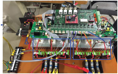
Experimental system.
Experimental results of the terminal voltage and speed.
Figure 11(a) shows the terminal voltage of OW-PMSM and traditional PMSM. Through the experiment, the terminal voltage of the open winding is increased by 33.6% compared with the general control system. Figure 11(b) shows the speed curve of OW-PMSM. The stability of the system is verified by adding rated load suddenly when the motor is running without load.
In this paper, an unity power factor control system and fault tolerant control system of permanent magnet synchronous motor based on the open winding configuration and three-phase four-switch topology. The block diagram of the proposed control strategy of OW-PMSM were first analyzed in detail. Then the simulation and experiment platform for the proposed inverter were built and the simulation and experiment ware carried out. As result, the simulation and experimental results have validated the performance and effectiveness of the inverter. Therefore, the proposed open winding inverter with low cost has great competitiveness in applications of motor control and the fault tolerance.
Footnotes
Acknowledgements
This research was jointly supported by the Project of Liaoning Education Department (No. 201634090), and project Support of Liaoning Science and Technology Department (No. 20180550037).