
Abstract
To obtain the static shape of the continuous steel plate and vibration characteristic, we performed the analysis of the multi-body dynamics in which the continuous steel plate was discretized in many solid bodies. The shape of the steel plate obtained by the measurement experiment was agreement with the static shape of the steel plate obtained by the analysis. Then, dynamical analysis was performed when white noise input to the steel plate. It was confirmed that the vibration could be suppressed when the electromagnets were installed in consideration of the static shape of the steel plate.
Introduction
Currently, steel plates are used in the manufacture of numerous industrial products, including those of the automobile industry. At steelworks, the length of a steel plate line is several kilometers, and during manufacture, a steel plate is tensioned as well as supported and conveyed by rollers. In the plating process, the distance between the rollers transported in the vertical direction for drying after plating is 20 to 50 m, and the traveling speed is 10 m/s or more. At that time, vibrations and waves are generated, and there are numerous quality problems such as peeling of the plating, peeling of the coating, and scratches on the surface. To solve these problems, some research groups proposed a non-contact guide system for the continuous steel plates. They installed electromagnets in the perpendicular direction with respect to the steel plate plane and suppress the vibration by control of attractive force from electromagnets [1–5]. However, these studies investigated at the part where the steel plate straightly travels and the vertical direction with respect to the traveling direction of the steel plate could not control. Our research group proposed non-contact guide control that enables vibration control in two directions by arranging electromagnets in the steel plate edge direction [6]. Moreover, to realize the steel plate with high surface quality, it is necessary to perform the noncontact guide at the section not only straight section but also the section where the traveling direction of the steel plate changes. We have installed electromagnets at the loop shape section and confirmed that arrangement of electromagnets along the shape of the traveling steel plate can suppress the vibration of the steel plate [7]. However, the shape of the traveling steel plate is experimentally obtained. Although the shape was investigated by the finite element method, it is not sufficient [8]. In addition, the vibration of the steel plate has not been investigated. In the first place, even a method for analytically obtaining the shape of a stationary continuum having bending rigidity like continuous steel plate has not been established. Therefore, in this study, we aim to obtain the static shape of the steel plate by using multi-body dynamics (MBD) analysis. Furthermore, the vibration characteristic of the steel plate was obtained by the analysis. Finally, we performed a traveling experiment by applying the analyzed shape of the guideway and considered guidance performance of the system.

Non-contact guide system.
Control system of the non-contact guide.
Model of the non-contact guide.
Outline of the non-contact guide system
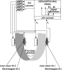
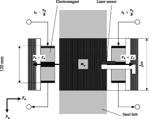
In this study, we examined a steel belt, whose size is length of 6894 mm, width of 150 mm and thickness of 0.3 mm to assume as the continuous steel plate in production line. The steel belt is hung on a pulley with diameter of 700 mm, as shown in Fig. 1. The pulley is driven by a DC servomotor to produce experimental condition which the continuous steel plate travels. 2 electromagnet units are installed to provide a non-contact guideway at lower part of the hung steel plate where the traveling direction is changed. The electromagnet unit consist of 2 pairs of serially connected electromagnets of 1005 turns, which are arranged to face each other near the edges of the steel plate, and a laser sensor to measure the gap between the steel plate and the electromagnet. The unit is controlled to keep the gap of 5 mm. Coordinates were defined as follows. The traveling direction of the steel plate at the electromagnet position is x direction, the vertical direction with respect to the traveling direction of the steel plate is the y direction, and the perpendicular direction with respect to the steel plate plane is the z direction.
Control system for non-contact guide
The control system is shown in Fig. 2. The displacements in the y direction of the continuous steel plate at each electromagnet unit are measured by its laser sensors. Measured displacement are input through A/D converter and are differentiated to obtain the velocities. These values are locally feed back only to each electromagnet units and the steel plate is actively controlled in y direction. On the other hand, although the z direction is non-control direction, the steel plate is passively guided to the center of the electromagnet. This is caused by the magnetic field generated for the positioning control in the y direction.
Control model of non-contact guide system
Figure 3 shows the control model of the non-contact guide system. According to our previous study [9], the state equation of the system is introduced from the equation of motion of the steel plate, i.e.,
Here, F0 is the magnetic force in the equilibrium state (0.83 N), 𝛤0 is the gap between the steel plate and the electromagnet in the equilibrium state (5 mm), I0 is the current in the equilibrium state (0.5 A), R is the resistance of the coupled magnet coils (20 Ω). Subscript n means the channel number of electromagnet unit (n = 1, 2).
Analysis model of multi body dynamics
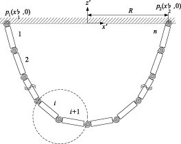
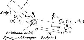
The continuous steel plates are suspended from p1 and p2 at both ends of a pulley of radius R shown in Fig. 4. The continuous steel plates were discretized into n bodies, and the shape when the bending stiffness and gravity were applied was obtained using MBD. Each body is connected with rotational joint, spring and damper, which assume bending stiffness of the steel plate and internal damping, as shown in Fig. 5. The length of each discretized body is l, width w, and thickness h. From the density 𝜌 of SUS632 used in the experiment, the mass m = 𝜌lwh and the moment of inertia I
r
= ml(2∕3) are calculated. The horizontal (x′-axis) and vertical (z′-axis) displacement and rotation angle in the i-th body (i = 1 − n) are defined as
The generalized coordinate q, which indicates the whole motion of the continuous steel plate, can be expressed by the following equation.
The applied forces in i-th body which are gravity in z′-axis, rotational spring and damping force are expressed as general force Q
i
as follows,
Analysis model of MBD.
Analysis condition between body i and i +1.
The mass and moment of Inertia of i-th body are expressed as
In the rotational joint between i-th and i +1-th body as shown in Fig. 5, the equation of constrain
The second derivative of the constraint equation gives the following equation.
Where
The number of body n = 116, body length l = 50 mm, plate thickness h = 0.1–0.5 mm in each 0.1 mm. The Young’s modulus E of SUS632 is 196 GPa, rotational damping ratio c is 0.1 Ns/m and the analytical time step is 20 μs. Parameter values used for other analyzes are listed in Table 1.
Static shape of the continuous steel plate is obtained by solving Eq. (12). Figure 6 shows the initial shape of the steel plate used for the analysis, and Fig. 7 shows the analysis results for each plate thickness. From Fig. 7, it is confirmed that the loop part at the bottom of the steel plate swells as the thickness of the steel plate increases. The measurement experiment of the static shape of the steel plate used in the experiment is conducted. Figure 8 shows comparison between analysis and experimental result, and these results agree to each other.
Vibration characteristics when a white noise is applied
To determine the vibration characteristics of the running continuous steel plate, the steel plate whose shape is obtained by the steel plate shape analysis in the previous section is excited by applying a white noise from its edge p1 as shown in Fig. 4. Figure 9 shows the spectrum waveform of each body every 1000 mm apart from the center of the steel plate when the white noise is applied. From these results, it is confirmed that all bodies vibrate in the same frequency band of 0.58 Hz.
Parameters of MBD analysis
Parameters of MBD analysis

Initial shape of the steel plate.
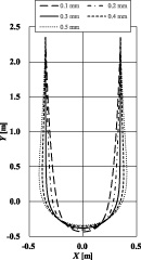
Analysis result.
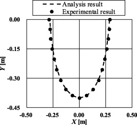
Comparison of the experimental result with the analysis result.

Spectra of analysis result of the excited continuous steel plate.
In this study, to investigate the effect of vibration on the continuous steel plate depending on its shape, electromagnet units were installed along the shape of the steel plate obtained by the analysis. Then, experiments were conducted in the case that the positions of electromagnet units were displaced inward and outward 0, 10 mm and 20 mm from the reference position which was obtained position by the MBD analysis in previous section. When the electromagnet units were displaced inward from analyzed position, electromagnets could not control the steel plate. The steady current of electromagnets was 0.5 A, and the traveling velocity of the steel plate was 1000 m/min. The displacement in the z-axis direction was measured 10 times by a laser sensor installed at 45° intervals from 0° to 180°, as shown in Fig. 10. We evaluated control performance by measured vibration in z-axis direction.
Figure 11 shows the results of z-direction displacement standard deviation at each measurement position. The vibration was most suppressed when the electromagnet units were placed in the reference position, and the vibration increased as the electromagnet units were displaced outward.
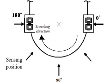
Measurement points.
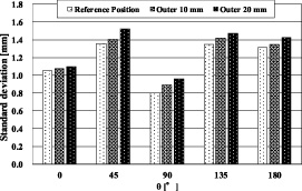
Standard deviation of displacement z.
In this study, we performed MBD analysis which the continuous steel plate was discretized in many solid bodies to obtain the static shape of the steel plate and vibration characteristic. The obtained static shape of the steel plate agreed with the actual shape obtained by measurement experiment. Then, dynamical analysis was performed in the case that the white noise input to the steel plate, it was confirmed that resonance frequency of each analysis body was same. It is considered that the frequency is modal resonance point. Finally, we performed the traveling experiment in the case that the electromagnet units were installed at the position referred to MBD analysis. Based on this, it was confirmed that the vibration could be suppressed by installation that the electromagnet units were installed considering the static shape of the steel plate. Therefore, we confirmed that grasping the static shape and vibration characteristics of the continuous steel plate can perform stable non-contact guide control.
Footnotes
Acknowledgements
This work was supported by JKA and its promotion funds from KEIRIN RACE.