
Abstract
To solve the problem of reduction of suspension force of permanent magnet system with variable magnetic flux path control, according to the structure of the system, suspension principle of the permanent magnet system with variable magnetic flux path control and the generation principle of the load torque, the influence of the mechanical structure of the system on the suspension force is analyzed by changing part of parameters of the system structure. The results show that the existence of magnetic isolation plate is the main reason for the decrease of suspension force, the permanent magnet ring can be thickened to 11.91 mm, the annular gap can be reduced to 1 mm, thickness of the “F” shaped magnetizer can be increased to 9 mm to increase the suspension force.
Introduction
Permanent magnet suspension system has the characteristics of no lubrication, compact structure and low thermal value. Due to the development of materials science, control technology, electromagnetic and other related technologies in recent years, permanent magnet suspension technology has been applied in aerospace, mechanical machining [1], life science community [2] and automobile [3]. Because permanent magnet suspension does not need lubrication and does not produce oil pollution in the working process, permanent magnet suspension is applied in various dust-free environments. The system proposed in this paper can be applied to dust-free transport occasions such as drug delivery and semiconductor delivery, the proposed two-side symmetrical structure can offset the load torque on the motor shaft to achieve zero power output, but it is found that the suspension force will also be reduced [4]. Researchers have also conducted extensive research on the influence of mechanical structure on the system [5]. On the basis of the previous research, the influence of the volume of permanent magnet ring, the parameters of magnetic isolation plate, the parameters of “F” shaped magnetizer on the suspension force was analyzed by using finite element analysis software.
The following are the main components of the paper. The suspension principle of the system is introduced in part two, the structure of the system and reduction of suspension forc are introduced in part three, the simulation of effect of system structure on suspension forceis analyzed in part four, the fifth part is the conclusion.
Suspension principle
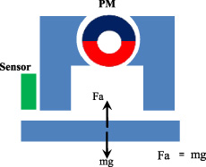
The suspension force is controlled by controlling the flux of magnetic line that flowing through the “F”-shaped magnetizer. When the permanent magnet ring is in the initial position, magnetic line of the N pole flows directly back to S pole without passing through suspension object, so the suspension force is zero; When permanent magnet ring turns a certain angle clockwise, a part of magnetic line start from the N pole and reaches the S pole through the right “F”-shaped magnetizer, suspension object and left “F” shaped magnetizer, the suspension force is generated [6].
Initial state of system.

The angle θ° of magnet.
Structure of the system
The permanent magnet system consists of a permanent magnet ring, two pairs of magnetic-conducting objects in which one pair is mounted on the front frame and the other pair is mounted on the backside frame, a suspension object, a magnetic isolation plate, a servo motor, frames, an eddy current displacement sensor and a couplings [7]. In the front side of the front frame, the permanent magnet ring is fixes on the shaft, the shaft is connected with servo motor by rigid couplings, permanent magnet ring can be driven by servo motor to rotate; two “F”-shaped magnetic-conducting objects are symmetrically placed on both sides of the permanent magnet ring and fixed on the system frame; suspension object is placed below the magnetic-conducting objects, one end of the suspension object is fixed to the system frame through a bearing, and the other end can swing freely; On the back of the rear frame, the “F”-shaped magnetic-conducting objects, suspended object and permanent magnetic ring are installed in the same position as on the front of the front frame, but the rear suspended object is fixed on the rear frame. Rotation around the X and Z axes and movement in the Y direction are limited by the front frame and bearing, movement in the Z direction is limited by the limit block and bearing. The displacement signal of the eddy current displacement sensor and the signal of the servo motor encoder are transmitted to the controller through A/D conversion. The controller is connected to the upper computer, Send the control signal to the controller by calculation, After D/A conversion and servo drive to drive the servo motor, Until the suspension reaches a stable state of suspension.

Structure diagram of the device.

One-side structure.

Two-side symmetrical structure.
It can be seen from the Fig. 4 that the proposed two-side symmetrical structure can well offset the load torque of the motor in the case of one-sided structure, but at the same time the suspension force is also reduced. In order to find out the influence of the system structure on the suspension force, the finite element simulation software was used to simulate and analyze the suspension force.
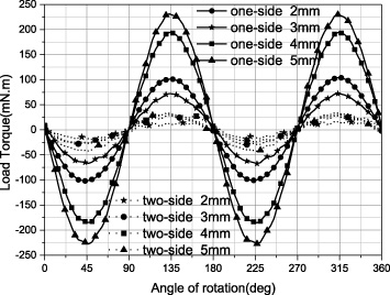
Comparison of load torque.

Comparison of suspension force.
Structure parameters of the system
Suspension force produced by the suspended object in the system [7]:
Load torque of motor in the system [7]:
This section presents the effect of system structure on suspension force by using simulation software. The simulation condition and simulation results are described below.

Simulation results of the influence of different volume of permanent magnet ring on suspension force.
Simulation conditions: The material of two “F”-shaped magnetic-conducting objects and suspension object are permalloy 1J85; The material of permanent magnet ring is NdFeB35; The material of magnetic isolation plate is iron.
In the case of one-side structure, the change of suspension force is compared by taking the non-thicker magnet ring, solid magnet with the same diameter and thicker magnetic ring with the same volume of solid magnets. The results show that the suspension force of solid magnet with the same diameter is the largest when the air gap is 2–5 mm, followed by the thicker magnetic ring with the same volume of solid magnets, and the lowest is the non-thicker magnetic ring.

Parameter of annular gap-‘k’.
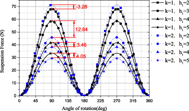
Simulation result of influence of annular gap on suspension force.
The size of the annular gap is change, the simulation results are shown in the Fig. 10. As is shown in the figure, Under the condition of h1 = 3–5 mm, the suspension force of 2 mm annular gap is smaller than that of 1 mm annular gap, the maximum difference of suspension force is 12.84 N; Under the condition of h1 = 2 mm, the suspension force of 2 mm annular gap is larger than that of 1 mm annular gap, the difference of suspension force is 3.28 N.
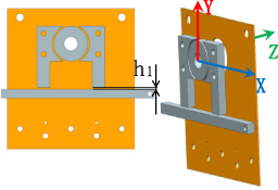
Diagram of simulation structure.

Comparison of suspension force.
The variation of the suspension force of one-side structure with magnetic isolation plate is shown in Fig. 11. The comparison of suspension force between one-side structure with magnetic isolation plate and one-side structure without magnetic isolation plate is shown in Fig. 12. As shown in Fig. 12, the suspension force will be greatly reduced by adding the magnetic isolation plate. The maximum value of suspension force decreases to 24.9 N and the minimum value of suspension force decreases to 8.2 N after adding magnetic isolation plate.
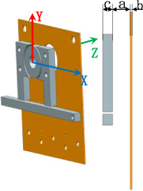
Diagram of simulation structure.
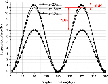
Simulation results of influence of different position of magnetic isolation plate on suspension force.
Take 4 mm air gap as an example, the influence of different distances (different values of ‘a’) from the magnetic isolation plate to the one-side structure on the suspension force is shown in the Fig. 14. With the increase of the distances, the suspension force becomes larger and larger. Considering other requirements, the distances should be increased as much as possible.

Simulation results of influence of thickness of magnetic isolation plate on suspension force.
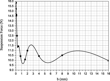
Variation trend of suspension force.
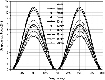
Simulation results of influence of thickness magnetizer on suspension force.
Variation trend of suspension force.
Take 4 mm air gap as an example, the influence of thickness of isolation plate(different values of “b”) on suspension force is simulated, the simulation result is shown in Fig. 15, the variation trend of suspension force is as shown in Fig. 16. It can be seen from Fig. 16 that the larger the thickness of the magnetic isolation plate, the smaller the suspension force is, and the most serious attenuation of the magnetic isolation plate is within 1 mm.
The influence of thickness of magnetizer on suspension force
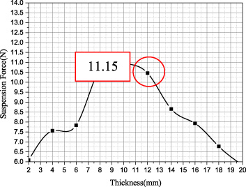
Take 4 mm air gap as an example. As shown in the Fig. 13, the suspension force varies with thickness of the “F”-shaped magnetizer. The variation of suspension force with the thickness ‘C’ of the magnetizer can be observed more intuitively through Fig. 18. It can be seen that the suspension force is the largest when the thickness of the magnetizer is 9 mm.
Conclusion
According to the suspension principle of the system, the load torque offset principle, the structural factors which may reduce the suspension force are analyzed, and the influence of different parameters of the system structure on the suspension force is simulated. The results show that the existence of magnetic isolation plate and the magnetic ring on the other side is the main reason for the decrease of suspension force, we can improve the suspension force of the system to a certain extent by adjusting the parameters of the mechanical structure in the system. According to the analysis results, the magnetic ring can be thickened to 11.91 mm, the annular gap can be reduced to 1 mm, the thickness of the “F”-shaped magnetizer can be increased to 9 mm to increase the suspension force.
Footnotes
Acknowledgements
This research is supported by LiaoNing Revitalization Talents Progra (No. XLYC1802077), Scientific research fund project of Liaoning Provincial Department of Education (No. LJGD2019011).