
Abstract
Reducing motor losses is very important in connection with raising the requirements set by international regulations on reducing electricity consumption. As induction motors are increasingly powered by high-frequency voltage, core losses starting to play a dominant role in motor loss balance. The presented paper shows how to calculate the basic and additional losses in the core of the induction motor, generated by the reluctance and slot harmonics of the magnetic field in the motor and by the higher harmonics produced by the inverter, using analytical and field-circuit methods. The results for motor operation at frequencies of supply voltage 10, 20 and 350 Hz were presented and compared with the results of measurements. The main achievement is the statement that losses in the core of the motor fed from the inverter should be calculated as the sum of losses generated by individual harmonics both in the motor and generated by the inverter.
Introduction
It is estimated that worldwide the production of variable speed drives for household appliances (washing machines, air conditioners and refrigerators) is approaching 100 million pieces of each type. Based on the data provided by the producers of these products and literature, it is estimated that significant part of them are low power drives with rated power from 0.2 kW to 3 kW [1–5]. In the literature one can find several items related to the adaptation of the construction of induction motor supplied by inverter. They resulted mainly from the use of frequency starting and, therefore, the possibility of abandoning the design solutions providing the appropriate value of the starting torque for the fundamental frequency [6–11]. Achieving high efficiency for a wide range of frequencies is possible by using sophisticated control systems that usually require rotor speed measurement [12–14]. In the analysed drives, operating at several clearly different frequencies [15,16], the use of induction motors without additional control systems using rotor speed measurement is dictated by both the simplicity of the solution and economic considerations. It should be emphasized, however, that in the induction motors used so far for such drives, generally designed for continuous operation with mains voltage of 50–60 Hz, efficiency at frequencies of 10–20 Hz (i.e. in the main operating conditions in the case of e.g. drives of industrial washing machines) is in the order of 30–60%, and at a frequency of 350 Hz is also clearly lower than at a frequency of 50 Hz, which is confirmed by tests carried out for currently produced motors. Therefore, increasing their efficiency requires a clear reduction of losses in both the core and motor windings. This paper addresses the problem of core losses in these types of motors because they are usually the most difficult to determine correctly and their role in the loss balance is significant. In the induction motors used in selected drives operating in a wide frequency range, the share of individual power losses depends significantly on the frequency of the supply voltage. Low frequencies are dominated by losses in the windings, while at higher frequencies - losses in the motor core. These losses are superimposed by additional losses caused by both higher harmonics generated by the motor and by the power inverter. Figure 1 shows averaged and approximate percentage shares of individual losses in an induction motor when supplied with a voltage with frequencies 10 Hz, 50 Hz [17] and 350 Hz.

Percentage share of motor losses at nominal load, at 10 Hz (a), 50 Hz (b) and 350 Hz (c) of supply voltage; 1 - losses in the stator winding, 2 - losses in the rotor winding, 3 - losses in the core (basic and additional), 4 - other additional losses, 5 - mechanical losses.
The increase in losses in the motor windings at frequencies lower than the mains frequency is mainly caused by the increase of the magnetizing current associated with the increase of magnetic induction at the decreasing frequency of the supply voltage and the need to maintain such voltage level so that the required electromagnetic torque of the motor can be obtained and a significant amount of higher harmonics generated by inverter at low frequencies.
The increase in losses in the core with the increase of the supply voltage frequency is mainly caused by the increase of additional, surface and pulse losses, generated by higher harmonics: reluctance and the stator and rotor slotting for individual harmonics generated by the inverter.
However, in this case, the share of higher harmonics in the voltage generated by the inverter is usually relatively small, so only the harmonics generated in the motor at the fundamental voltage harmonic of the inverter can be considered in the calculation.
The main purpose of the work is to show what is the impact on the total losses in the motor core of additional losses generated both by the harmonics of the magnetic field in the motor, even when powered by the basic voltage harmonic, and by the harmonic voltages generated by the inverter. The motor operation at various frequencies of the supply voltage, i.e. 10, 20 and 350 Hz, will be analysed, because in such power conditions the motor works to drive the industrial washing machine, which is the object of research.
The test object is a low-voltage, quadripolar, low-power induction motor with shaft heights 71 mm (the height from the base of the motor to the shaft end axis in mm), designed for operation at 10, 20 and 350 Hz power supply frequencies (typical for industrial washing machines: 10 Hz - start-up, 20 Hz - washing and 350 Hz – spinning). The outer diameter of the stator package and the length of the stator core are 120 mm. This motor has 36 stator slots, 114 serial turns per phase, 32 rotor drop shape slots, whose relative skew in relation to the tooth pitch of the rotor is 1.34.
In order to measure the characteristics of the motors in a broad range of loads and supply parameters, a versatile measurement circuit was built [18].
For this motor, calculations of electromagnetic parameters and power losses were made using the own STAT_WIN program using the motor’s analytical model and the field-circuit method, using the commercial OPERA 2D package for the motor load conditions with the rated torque at the given frequency of the supply voltage. The STAT_WIN program is authors own program for calculating electromagnetic parameters and operating characteristics of induction motors both at mains and inverter power supply, in which the core loss calculations are based on measured and approximated loss characteristics of electrical sheets in the frequency range from 10 to 14,000 Hz [20], with taking into account higher harmonics generated in the motor and by the inverter [19].
The method of calculating core losses based on the FEM 2D, multislice to take into account the rotor skew, solution in time domain, described in more detail in papers [18–20], was used. In the literature, we can find many approaches to solve this problem [22], but the use of an appropriate material database is crucial here [20]. For the same conditions, laboratory measurements were made to verify the obtained calculation results.
Figure 2 shows the model of the motor in the Opera 2D environment along with the rotor circuit, while Fig. 3 shows the finite element division mesh. The end parts of the stator windings are represented by lumped parameters calculated by analytical methods in the STAT_WIN program. The same procedure applies to the shorting ring of the rotor cage. These lumped parameters are connected with FEM model as shown for example for rotor in Fig. 2. The 2D model exploited motor symmetry. In investigated motor due to stator and rotor symmetry it was possible to analyse a quarter of the motor using the anty-periodicity condition. The finite element mesh consists of 8387 elements with 5582 nodes with average element size (the length of the longest side of the triangle) equal to 0.25 mm in near air gap region. Rotor movement was possible to consider in the model due to the use of a gap element [23]. For this purpose, the air gap of the motor is divided into three parts: one connected to the stator, the other connected to the rotor and a connecting layer (gap region). The number of divisions is selected so that the elements created in the gap region are closest to equilateral triangles. Because the motor has a skew of the rotor slots, the multi-slice model is used with 5 slices evenly rotated (skew angle is approximately 15 degrees) [24]. The transient field-circuit coupled magnetic field equations are discretized in time by the Galerkin weighted residual method in the time domain [25]. Adaptive time stepping method have been used with average time step equal to 3.57 μs. Choosing the right step is especially important when the motor is powered by voltage from the PWM inverter with maximal carrier frequency 14.5 kHz.
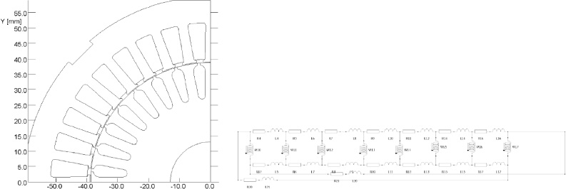
The model of the motor in the Opera 2D environment along with the rotor circuit.

Finite element mesh in Opera 2D environment.
The tested motor at the frequency of the 10 Hz supply voltage must achieve a shaft torque of not less than 7.8 Nm, which requires the creation of an appropriate magnetic flux in the motor. Therefore, a 4% boost of the initial voltage supplying the motor is used. Boost means that the voltage, and therefore the flux, are respectively larger than would result from a constant proportion of voltage to frequency. Figure 4 shows the harmonics of the voltage generated by the inverter at the fundamental harmonic frequency of 10 Hz. In this case, in calculations using a field-circuit model, losses was calculated by supply the motor only with the fundamental harmonic of the voltage, thanks to which losses resulting from higher harmonics of the magnetic field in the motor were determined, shown in Fig. 5 and in Tables 1 and 2.

The harmonics of the supply voltage at the output frequency of 10 Hz.

The losses in the stator and rotor core for higher harmonics at the supply of the 1st harmonic of the 10 Hz voltage.
Core losses for selected dominant field harmonics generated in the motor with the supply of the fundamental harmonic of 10 Hz voltage (stator basic losses 3,54 W) – field-circuit model
The results of calculations of losses for the load state of the motor at supplying by 1 harmonic voltage of 10 Hz (mechanical losses P m = 0,65 W, rotational speed n = 208,8 RPM, torqueM = 7,796 Nm)
As it results from Table 1 and Table 2, the ratio of core losses calculated taking into account the higher harmonics generated in the motor when powered by the basic voltage harmonic voltage of 10 Hz to the basic losses is 2.24, with losses generated by the 12th harmonic of the stator and rotor field playing the dominant role.
The losses in the core calculated by the analytical method are in this case about 20% smaller than the value obtained as a result of the field-circuit method, which is due to the fact that the analytical calculations take into account the lower number of higher harmonics generated in the motor than in the field calculations.
The dominant higher harmonics generated by the inverter, shown in Fig. 4, were also taken into account in calculations performed using the circuit model. They were also made, using the circuit analytical method, calculation of losses caused by the dominant higher harmonics generated by the inverter (Table 3).
Core loss values for selected dominant harmonics of the supply voltage generated in the inverter
Table 4 gives a comparison of the motor losses calculation results obtained using the circuit analytical model with the measurement results when the motor is powered from the inverter.
The results of calculations of losses for the load state of the motor at supplying by inverter voltage of 10 Hz (mechanical losses P m = 1,7 W, rotational speed n = 208,8 RPM, torque M = 7,796 Nm)
Based on Tables 3 and 4, it can be stated that the core losses caused by harmonics generated by the inverter are in this case almost 2.5 times greater than the losses occurring when the motor is powered, only by the basic harmonic. This is due to the very high proportion of higher harmonics in the voltage generated by the inverter at a fundamental harmonic frequency of 10 Hz.
The differences between analytical calculations and measurements are due to the fact that at a frequency of 10 Hz very high magnetic induction values occur in the motor core, so in the calculations not only measured, but also approximated, for the induction values outside the measuring range, approximate magnetizing and specific losses characteristics are used for core material.
Shown in Fig. 6 distribution of the magnitude of magnetic flux density for the load condition of the motor with the rated torque, at voltage supply with a frequency of 10 Hz shows that under these conditions the motor yokes and teeth exhibit large magnetic induction values, resulting in the notable magnetizing current of the motor and, consequently, also the current in the stator winding, which is an additional cause of significant power losses in the machine windings. Calculated values of total losses and motor efficiency, while supplying the motor only by the fundamental harmonic frequency of 10 Hz and taking into account the dominant higher harmonics of the voltage generated by the inverter were compared with the values measured shown in Fig. 7. These values were calculated using the analytical circuit model, taking into account the winding and reluctance higher harmonics of the magnetic fields generated in the motor by individual harmonics of the inverter voltage. As is apparent from the presented values, the omission of the harmonic voltage generated by the inverter operating the motor at an output frequency of 10 Hz causes a significant underestimation of total loss occurring in the motor and increasing its apparent efficiency, especially when the motor load increases by about 3%.

Distribution of the magnitude of magnetic flux density for the load condition of the motor with the rated torque, at voltage supply with a frequency of 10 Hz.

The values of total losses and motor efficiency, while supplying the motor by PWM inverter by the fundamental frequency of 10 Hz.
The tested motor at the frequency of the 20 Hz supply voltage must achieve a shaft torque of not less than 9.8 Nm, which requires the creation of an appropriate magnetic flux in the motor. Therefore, a 4% boost of the initial voltage supplying the motor is used as for 10 Hz. Figure 8 shows the harmonics of the voltage generated by the inverter at the fundamental harmonic frequency of 20 Hz. In this case, the losses were calculated using the field-circuit model (Fig. 9) and the analytic circuit model, both when the motor was powered by only one harmonic (Tables 5, 6) as well as all the harmonics generated by the inverter (Tables 7, 8, 9).

Harmonic content of the supply voltage at the output frequency of 20 Hz.

The losses in the stator and rotor core for higher harmonics at the supply of the 1st harmonic of the 20 Hz voltage.
Core losses for selected dominant field harmonics generated in the motor when supplied with the fundamental harmonic of 20 Hz voltage (basic stator losses 8,53 W) – for field-circuit model
The results of calculations of losses for the load state of the motor at supplying by 1 harmonic voltage of 20 Hz (mechanical losses P m = 1,7 W, rotational speed n = 521,2 RPM, torqueM = 7,76 Nm)
Core loss values for selected dominant harmonics of the supply voltage generated in the inverter, calculated using circuit model
Core losses for selected dominant field harmonics generated in the motor when supplied with the entire voltage generated by the inverter (basic losses 8,57 W in stator) – field-circuit model
The results of calculations of losses for the load state of the motor at supplying by inverter voltage of 20 Hz (mechanical losses P m = 0,65 W, rotational speed n = 521,2 RPM, torqueM = 7,796 Nm)
When supplying the motor, the basic voltage harmonic with a frequency of 20 Hz, can be stated from Table 5 and Table 6 that in this case the ratio of core losses calculated taking into account the higher harmonics generated in the motor to the basic losses is 1.9 and is slightly lower than at the basic harmonic frequency equal to 10 Hz.
Table 9 gives a comparison of the motor losses calculation results obtained using the circuit analytical model and field – circuit model with the measurement results when the motor is powered from the inverter. Figure 10 presents a comparison of harmonic losses generated in the motor’s core while supplying by 1 harmonic voltage with a frequency of 20 Hz and the entire voltage from the inverter.

The losses in the stator and rotor core for higher harmonics when the motor is powered from the inverter with a voltage of 20 Hz frequency.
Based on Tables 7–9, it can be concluded that core losses caused by harmonics generated by the inverter at a fundamental harmonic frequency of 20 Hz are about 1.25 to 1.45 times higher than losses occurring when the motor is powered, only by the basic harmonic. In this case, the proportion of higher harmonics in the motor supply voltage, especially at lower frequencies, is clearly smaller than at 10 Hz.
Calculated values of total losses and motor efficiency, while supplying the motor only by the fundamental harmonic frequency of 20 Hz and taking into account the dominant higher harmonics of the voltage generated by the inverter were compared with the measured values shown in Fig. 11.

The measured and calculated total losses of the motor and its efficiency when powered from the inverter at a frequency of 20 Hz.
As shown in Fig. 11, when the motor is running at a 20 Hz output frequency, the effect of higher harmonics generated by the inverter on the total loss values in the motor and its efficiency is much smaller than at the basic frequency of 10 Hz, because despite the similar share of higher harmonics in the voltage generated by the inverter, their relative values in relation to the basic harmonics are smaller.
In this case, the apparent increase in the efficiency of the motor at its maximum load moment does not exceed 1%.
The tested motor at the frequency of the 350 Hz supply voltage must achieve a shaft torque of not less than 1.3 Nm. For 350 Hz motor is supply by maximum available from the inverter voltage of 230 V. Motor for 350 Hz is working at field weakening region because maximum voltage is reached for 77 Hz. For low frequency 10 Hz and 20 Hz voltage is increased from linear dependence by using a small voltage increase defined as boost. Figure 12 shows the harmonics of the voltage generated by the inverter at the fundamental harmonic frequency of 350 Hz. In this case, losses was calculated by supply the motor only with the fundamental harmonic of the voltage, thanks to which losses resulting from higher harmonics of the magnetic field in the motor were determined, shown in Fig. 13 and in Table 10.

The harmonic content of the supply voltage at the output frequency of 350 Hz.

The losses in the stator and rotor core for higher harmonics at the supply of the 1st harmonic of the 350 Hz voltage.
Core losses for selected dominant field harmonics generated in the motor when supplied with the fundamental harmonic voltage of 350 Hz (basic losses 22,11 W) – field-circuit model
When supplying the motor, with the basic harmonic voltage of 350 Hz, it is dominated by additional losses in the core caused by higher harmonics generated in the motor and they are almost seven times higher than the basic losses.
Table 11 presents the core losses caused by the dominant higher harmonics generated by the inverter calculated with use circuit analytical method.
Core loss values for selected dominant harmonics of the supply voltage of 350 Hz generated in the inverter, calculated using analytical circuit model (mechanical losses P m = 81,4 W, rotational speed n = 10105,2 RPM, torque M = 1,3 Nm)
Table 12 gives a comparison of the motor losses calculation results obtained using the circuit analytical model and field – circuit model with the measurement results when the motor is powered from the inverter.
The results of calculations of losses for the load state of the motor at supplying by inverter voltage of 350 Hz (mechanical losses P m = 81,4 W, rotational speed n = 10105,2 RPM, torqueM = 1,3 Nm)
The influence of higher harmonics generated by the inverter is very low at the fundamental harmonic frequency of the supply voltage of 350 Hz and causes a rise in the core losses below 10% (7.5%).
As can be seen from Fig. 14, the flux density level in the motor for 350 Hz power supply is quite low (0.7 T) compared to 10 Hz or 20 Hz operation (1.8 T). This is because for this frequency the motor is already working in the field weakening region because of the limited voltage at DC input. Low saturation of the magnetic circuit additionally increases losses from higher harmonics.

Distribution of magnitude of magnetic flux density for load state (right magnitude of first harmonic of induction).
Figures 15 and 16 show selected harmonics of magnetic flux density. These are harmonics produced by the rotor slots (32 slots from here 16 harmonics). As you can see their impact extends over a large area of the stator, hence despite the small amplitude and frequency, the losses caused by them are significant. A potential method of limiting these losses would be the use of closed rotor slots, however, this reduces the torque developed by the motor due to the reduction of the main flux. Because the main flux is still smaller compared to the low frequencies, it is impossible to get the torque we need.

Distribution of magnitude of magnetic flux density for load state for 15 and 16 harmonics.

Distribution of magnitude of magnetic flux density for load state for 29 and 30 harmonics.
Figure 17 however shows harmonics produced by the stator slots (36 slots). As can be seen, they are formed mainly in the tips of the rotor teeth. The increase in frequency associated with the increase of the harmonic order means that a relatively small area of influence can generate noticeable losses. A possible countermeasure could be the use of magnetic wedges in the stator. However, the availability of wedges with the required parameters is limited and opinions on their use vary [26]. Part of the harmonics is created by the interaction of the slotted rotor and stator (shown in Figs 18 and 19). The presented harmonics are the result of the in time distribution for individual division mesh elements. The order of harmonics results from the number of rotor and stator slots, with the harmonics of the lower orders resulting from the impact of the group of slots. The harmonics of the lower rows are found throughout the core, while the harmonics of the higher orders are concentrated mainly near the air gap. Unfortunately, the ability to influence the limitation of losses generated by higher harmonics (considerably exceeding for frequency 350 Hz the basic losses) is limited. Calculated characteristics of total losses and motor efficiency, while supplying the motor only by the fundamental harmonic frequency of 350 Hz and taking into account the dominant higher harmonics of the voltage generated by the inverter were compared with the characteristics measured in Fig. 20. As shown in Fig. 20, when the motor is running at an output frequency of 350 Hz, the effect of higher harmonics of the voltage generated by the inverter on the total loss values in the motor and its efficiency is practically negligible in the whole load range of the motor. In this case, the apparent increase in the efficiency of the motor at its maximum load torque does not exceed 0.5%.

Distribution of magnitude of magnetic flux density for load state for 17 and 35 harmonics.

Distribution of magnitude of magnetic flux density for load state for 44 and 76 harmonics.

Distribution of magnitude of magnetic flux density for load state for 52 and 87 harmonics.

The measured and calculated core losses, total losses of the motor and its efficiency when powered from the inverter at a frequency of 350 Hz.
Calculation of losses in the core of the motor supplied from the inverter requires taking into account both the higher harmonics of the magnetic field generated in the motor by the basic harmonics of the supply voltage and by the dominant higher harmonics produced by the inverter, whose contribution is particularly significant at low frequencies of the supply voltage. When calculating the efficiency of the motor using the analytical circuit model, calculations for all the dominant harmonics of the voltages generated by the inverter should be made and the sums of individual components of these losses should be taken into account. It should be emphasized that for each harmonic voltage of the inverter, additional losses in the stator core must also be taken into account due to the higher harmonics of the magnetic field generated in the motor. The work showed that for virtually all frequencies, even when supplying the motor with sinusoidal voltage, additional losses in the core caused by higher harmonics of the magnetic field in the machine under load, even at low motor operating frequencies, are comparable to the basic losses (for the tested motor for a frequency of 10 Hz additional losses to basic losses is 1.24, and for 20 Hz - 0.9) while for high frequencies they are many times higher than basic losses (for 350 Hz the ratio of additional losses to basic losses is 7.68). The increase in core losses due to harmonics generated by the inverter depends on the proportion of these harmonics in the inverter voltage and is much higher for low frequencies (for the tested motor at 10 Hz the ratio of losses at inverter power to losses at power supply is 2.5, and for 20 Hz - about 1.3) than for higher frequency (for 350 Hz the ratio of loss at inverter power to losses at power supply is less than 0.1).
In addition, when supplying with low frequency voltage, there are large magnetic flux density values exceeding the values for which it was possible to measure magnetizing characteristics and specific losses of the core material. This is a source of additional errors both for analytical and field-circuit simulation, despite the use of different extrapolation methods.
Footnotes
Acknowledgements
The work is carried out partly (65%) within the framework of the research project POIR.04.01.04-00-0002/16 “Developing a new optimized from the point of view of power loss design high speed three phase induction motors used in industrial drives”, financed by NCBiR within the Operational Program Intelligent Development 2014–2020.