
Abstract
A temperature rise occurs when an electrical machine is fully loaded. The winding insulations of high-speed permanent magnet synchronous machines (PMSMs) are the most temperature-sensitive components, which can impact the machine’s longevity. Thus, recently, prediction for high-speed PMSM winding temperature has been given more and more attention. Thermal analysis by numerical (computational fluid dynamics (CFD) and finite element method (FEM)) and analytical lumped parameter thermal network (LPTN) methods have been widely used to estimate the temperature of totally enclosed fan cooled axial ventilation system (TEFCAVS) machines. Although numerical methods have more accuracy, their computation wastes time. Therefore, LPTN is being utilized in this paper due to the fastness of its computation. Firstly, estimated losses of high-speed PMSM with TEFCAVS via electromagnetic analysis, including copper, iron, permanent magnet (PM) eddy current, sleeve eddy current, and mechanical, are coupled to the LPTN model, which acts as heat sources for temperature prediction. Moreover, analysis shows that slot windings’ maximum temperature exceeds the winding insulation class with initial cooling configuration. Secondly, in order to mitigate slot winding temperature, the sensitivity study for liner conductivity, air gap’s heat transfer and lamination to housing’s contact is conducted by LPTN to identify which thermal parameter has more influence on mitigating the maximum temperature of the slot winding. Investigation shows that improving an air gap’s heat transfer has more influence than other parameters for mitigating slot winding maximum temperature below its insulation class. Lastly, the machine is designed and tested with the best thermal-sensitive parameters. Then test results for the maximum temperature of the winding are compared with estimated results to ensure the proposed LPTN correctness, and the calibration process confirms LPTN accuracy.
Introduction
As a result of their excellent functionality, high-speed PMSMs are utilized across a large number of industrial sectors, like distributed power production, gas compressor, turbine and energy storage [1–3]. They are compact and have high power density, and because they do not have a gearbox, they could be used in direct-drive applications. Furthermore, in comparison to reluctance and induction motors, they are favourable since they demonstrate extraordinary high efficiency even at high working speeds. However, they have unique issues due to the high power density that can be achieved by applying a high-frequency current to a stator winding, resulting in a large increase in winding losses. Similarly, the iron loss will be significantly higher than the conventional motor due to the high alternating field in the steel core lamination. The resulting increase in copper loss and iron loss, if not dissipated properly, will lead to temperature rise in both stator winding and stator iron, respectively, which can affect the thermal performance of the machine.
Because heat is concentrated quickly, even a little increase in winding temperature is dangerous [4]. The winding insulations inside the stator slot are the most temperature-sensitive element of a high-speed PMSM, and they will deteriorate first if the operating temperature is exceedingly high. It results in an inter-turn and phase short circuit, resulting in total machine damage. Hence, it is extremely important to estimate the slot’s winding temperature accurately to ensure that its temperature is within the maximum allowable value. Therefore, it is compulsory to have a thermal model in the early machine design process.
Generally, two well-known methods are available in the literature: numerical (FEM and CFD) and analytical (LPTN) methods. The FEM solves heat distribution directly within the solids part of the machine, while CFD gives more detail on fluid’s behaviour inside the machine in addition to the heat distribution. In contrast, LPTN uses an equivalent thermal circuit to model heat transfer inside the machine via a similitude between a physical quantity describing a heat flow and a current flow. Despite numerical methods having more accuracy, analytical LPTN is still being used frequently in the thermal modelling of high-speed PMSM because of its fastness in the computation, compared to numerical methods.
In the literature, there are several works on thermal studies utilizing the LPTN of an electric machine using forced air cooling, such as radial flux machines and axial flux machines, as detailed in [5,6]. The LPTN of an air-cooled high-speed PMSM is described in [7], and the thermal resistance coefficient determines the correctness of the proposed LPTN thermal model. While analyzing the airflow and temperature distributions within the high-speed PMSM, numerical approaches (CFD and FEM) provide more fluid behaviours and thermal properties [8–10]. However, the above methods are complicated and time-wasting in the early design process, especially for thermal analysis of high-speed PMSMs due to their compact and complex structure. Moreover, according to the authors’ knowledge, no works in the literature have reported thermal analysis of high-speed PMSM with TEFCAVS by LPTN considering the airflow mechanism and critical thermal parameters influencing slot winding maximum temperature rise.
In this work, high-speed PMSM thermal analysis of TEFCAVS for centrifugal blower application is presented by LPTN. Firstly, before LPTN analysis, electromagnetic analysis is conducted to account for copper and iron loss, PM eddy current loss, sleeve eddy current loss and mechanical loss, which serve as heat sources in the LPTN model. Then an airflow model for TEFCAVS is introduced to ensure an air volume flow rate is provided adequately for uniform slot winding temperature distribution in the high-speed PMSM. Moreover, sensitivity analysis for liner conductivity, air gap’s heat transfer and lamination to housing’s contact are conducted by LPTN to identify which thermal parameter has more influence on mitigating maximum temperature of the slot winding. Investigation shows that improving the air gap’s heat transfer has more influence than other parameters. Furthermore, a quick and precise LPTN considering an optimal airflow and thermal parameter of high-speed PMSM with TEFCAVS is presented. Finally, the machine is thermally tested for air suspension centrifugal blower application. The estimated and measured results of the winding temperature are compared to validate the LPTN model’s accuracy; an error illustrates the criterion for evaluating the accuracy of the LPTN, which is proven by the calibration procedure.
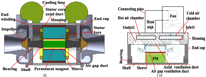
Structure of 225 kW high-speed PMSM. (i) Prototype structure in 3D half-cut view. (ii) 2D cut view structure of the two parallel ventilation ducts inside the prototype with the air cooling passageways.
Prototype’s parameters
Generally, compared to low-speed PMSM, the length of an axial high-speed PMSM is long with a large length to diameter proportion; therefore, the TEFCAVS is preferred for this machine’s cooling configuration. The structure of the prototype in a 3D half-cut view of the machine is shown in Fig. 1(i); two parallel ducts inside the machine for ventilation with cooling passageways are demonstrated in Fig. 1(ii), and Table 1 shows its nameplate parameters.
An electromagnetic study is conducted to account for the HSPMSM losses. Two rotor options for high-speed PMSMs structure are interior PM and surface mounted.

Finite element analysis results. (i) Sinusoidal current waveform at rated load condition. (ii) PWM waveform current of the converter with harmonics at rated condition. (iii) Spectrum for the current harmonics. (iv) 2D FEM distributions of flux density.
The latter is considered a better option because it can handle significant stress arising from high-speed rotor rotation. At the same time, the former has a higher power density; an excellent selection of PM material is also needed for high-speed PMSMs: SmCo tolerates temperature up to 300 °C, whereas NdFeB benefits with enhanced coercive force and greater remanence. NdFeB mechanical strength is better than SmCo, which is essential for high-speed operation. In this study, a SmCo-based surface-mounted PMSM is used.
Principally PMSM converts electrical energy to mechanical energy. Loss is always manifested along the conversion process, which is obtained by a difference between the mechanical power output and the electrical power input. The maximum power output for the high-speed surface-mounted PMSM is limited by the core’s maximum permissible magnetic flux density (Bmax) and the winding’s maximum allowable linear current density (Amax). However, the maximum flux density depends on the properties of the magnetic materials, and it is affected by temperature. In contrast, the maximum permissible current is mainly limited by the maximum acceptable temperature for the insulation; thus, the maximum permitted current density value is determined by the type of cooling available to the machine and the machine’s size and enclosure type. Therefore, 225 kW high-speed PMSM with TEFCAVS in this paper has the numerical value of core’s maximum permissible magnetic flux density and winding’s maximum allowable linear current density as 2.6 T and 6.02 A/mm2, based on the Armon silicon 73.5% Si core material property and forced air cooling, respectively.
Therefore, a very fast and accurate temperature estimation method is necessary to predict the thermal performance of the machine accurately; this helps to maintain the material’s magnetic properties and keep the insulation temperature within the acceptable range. The results for the machine’s sinusoidal current waveform at rated load condition and PWM waveform current of the converter with harmonics spectrum at rated condition alongside 2D FEM distributions of flux density are shown in Fig. 2.
Iron losses, copper losses, and PM eddy losses are the primary losses that contribute to temperature rise inside an electric machine [11]. In the thermal model, these losses must be precisely computed in order to anticipate the real temperature prediction for the essential parts of the motor, such as the winding and a permanent magnet. With advancements in equipment processors and software platforms, determining the loss using a finite-element approach is preferred. The 2D finite element approach was used to evaluate high-speed PMSM fundamental losses, including copper and iron losses, with PWM and sinusoidal current excitation, as shown in Fig. 3(i). The time-stepping finite element method estimated rotor eddy current loss, including the sleeve and permanent magnet. The mechanical loss was obtained from the manufacturer’s datasheet. The machine’s loss breakdown at maximum speed is shown in Fig. 3(ii), where the copper loss occupied the highest percentage compared to other types of losses.
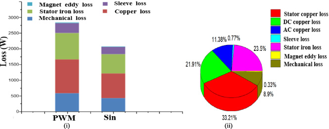
Estimated losses (i) with PWM and sinusoidal current excitation. (ii) Loss breakdown at maximum speed.
Total losses in the high-speed PMSM can be expressed analytically as:
Loss generated in the winding accounts for the stator copper winding. While the loss for rotor iron is not considered due to the fundamental rotating magnetic field rotates at the same speed of the rotor, in the loss estimation for iron, only for the stator and loss for eddy current on the rotor are considered. Thus, the above equation can be expressed as:
The network defined as the airflow model accomplishes an airflow estimation inside the high-speed PMSM. It is made up of an active device that produces air pressure and an air pressure resistance device that resists pressure and refers to all of the ventilation circuit’s passive components. By combining the pressure drops across both passive devices, an air pressure generated by two fans is estimated. As a result, the network model for the airflow of 225 kW high-speed PMSM is created using the details of the TEFC AVS structure, as illustrated in Fig. 4.
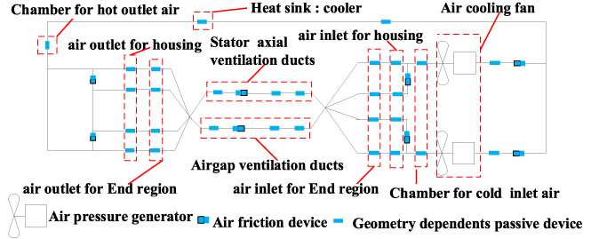
A proposed airflow network model.
The air-cooling fan is selected based on the ventilation system’s air coolant quantity and air coolant pressure losses across the overall air coolant flow paths, as shown in Fig. 5.
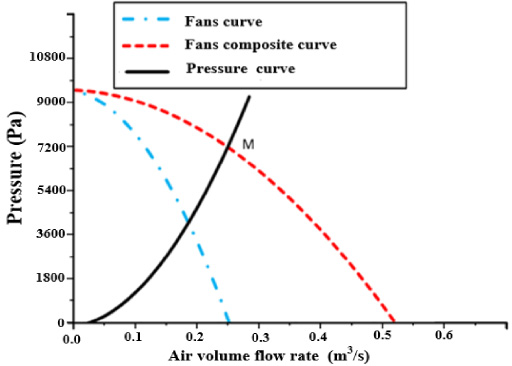
Fans characteristic and pressure impedance for the 225 kW high-speed PMSM.
Due to the high volume of air needed by the ventilation system, this machine adopts two centrifugal fans, which operate laterally to ensure an air volume is provided adequately. Two parallel fans composite curve characteristics and pressure impedance curve is illustrated in Fig. 5 for the ventilation structure. Point (M) where the two curves meet indicates the airflow operating points.
According to coefficients for convective heat transfer. The relation (5) estimates an air coolant’s volume flow rate analytically.
The summation of the pressure losses estimates the drops in pressure due to friction and changes in geometry and the pressure drop (ΔP) due to changes in geometry, including contraction, expansion, and bend. It is expressed as follows:
The relation that derives the pressure drop due to friction is expressed as:
Heat transfer and thermal design are just as significant as electromagnetic design; they have higher complications and nonlinearities due to the fluid flow aspect [13]. Machine designers have traditionally employed D xL formulas or the sizing method, which is not a direct method of thermal analysis to restrict magnetic and current loading [14]. In some situations, they designed the machine based on past experimental results. In others, they built a fundamental resistive network that can be estimated manually; for certain circumstances, the resistive network is composed of one resistance [14]. New thermal approaches were introduced at the beginning of the twenty-first century as the computer’s involvement in the design process of electric machines grew and the complexity of thermal networks increased. Analytical and numerical methods [15,16], and [17] are the two primary categories of modern electrical machine thermal design.
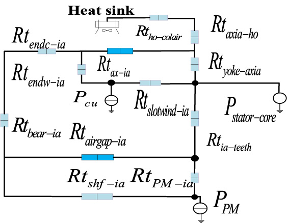
The LPTN is derived using an analytical approach to calculate the temperature of the key parts of an electric machine, like the winding. Because the electrical engineers are aware of the concept of an electric circuit, they would find the LPTN to be more understandable [14]. The electric circuit’s equivalent is the LPTN [14]. As a result, the temperature at a particular node equals voltage, power loss equals a current source, and thermal resistances equal electric resistances [14]. This method has the advantage of short computational effort [18]. Thermal resistances are evaluated using empirical relationships derived from various simplifying assumptions or tests [19], leading to inaccuracies. This paper’s lumped thermal parameter network of 225 kW high-speed PMSM is set up based on the machine’s structural components and ventilation system, as illustrated in Fig. 5. The machine’s structural parts and air coolant’s flow paths along axial direction can be divided into two in the LPTN model to estimate temperature distributions accurately.
The proposed thermal network for the lumped parameter is used to estimate the structural part’s and cooling air temperature for the high-speed PMSM; the reference air coolant’s (cold air) temperature is set to 20 K. Based on the presented thermal network model, the methodology is explained in the following. Firstly, it becomes mandatory to guess an initial temperature for every air coolant’s fluid device. The LPTN is used to obtain the machine’s structural part’s temperature. Then, each device’s temperature can be estimated under the heat gained by the air coolant in each region. Finally, under the deviation between the estimated and assumed value of air coolant devices, the iteration continues until the requirement is met. The hexagon notations represent the machine’s structural components, and the square notations represent the gaps used for the air coolant’s flow pathways in the proposed LPTN, as shown in Fig. 6.
The lumped parameter thermal network (LPTN) consists of thermal resistance, thermal capacitance, and heat source. Since the electrical machine is cylindrical, every cylindrical component of the machine is described by LPTN that comprises heat source, axial resistance, and radial resistance. The explanation of thermal resistance in LPTN is connected with the material thermal conductivity and its dimension. As a result, the heat transfer mode for the high-speed PMSM in this research is classified into conduction and convection.
Estimation of thermal resistance
Because copper loss is the major loss component of the machine and slot insulations are very susceptible to temperature rise; therefore it is essential to model a region of slot winding. The model of individual wires is unnecessary. Figure 7(ii) shows how the compounded 3D section of the cylinder builds the slot-winding region, which contains copper conductor, wire insulation, and impregnation, without changing its shape.

Proposed thermal network model of 225 kW high-speed PMSM.
The lumped parameters of the slot winding thermal network that consider heat flow pathway along an axial, circumferential, and radial direction are presented in Fig. 7(iv); an axial, radial and circumferential equivalent thermal conductivities are estimated based on the H+S method in [20]. In Fig. 7(i) and (iii), thermal resistances in the axial and radial directions are calculated using the approach described in [21], as given in Table 2.
Where 𝜆 ax and 𝜆 rad represent thermal conductivities along with axial and radial directions, respectively, L represents machine length along an axial direction r 1 and r 2 indicates an inner and outer radius for the cylindrical components of the machine, T 1 and T 2 are the unknown two end faces nodal temperatures, T 3, and T 4 represent the unknown inner and outer surface temperature, T m represents the component’s average temperature, P denotes the internal loss.
Thermal conduction resistance
When addressing the heat flow route across stator teeth and slot winding in this paper, as shown in Fig. 7(ii) and (iv), therefore, the thermal resistance via the circumferential region is expressed as [22]:
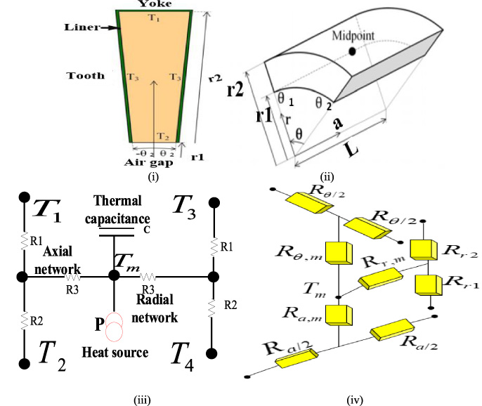
Reduced LPTN of slot winding. (i) Slot cross-section. (ii) Hollow segment of cylinder. (iii) Axial and radial thermal network. (iv) 3D thermal model.
The value of radial, axial, and circumferential thermal conductivities for different machine components are given in Table 4. Where I G = impregnation goodness, d l = iiner thickness, k f = wire slot fill, 𝜆θ represent circumferential thermal conductivity.
Slot winding parameters
Two different methods present the estimation for equivalent thermal conductivities along the radial and axial directions inside the slot are presented in [20] by two different methods. Namely, Hashin and Shtrikman approximation modified Hashin and Shtrikman approximation by taking conductors’ insulation into account and assuming conductors’ insulation has similar thermal conductivity with the surrounding encapsulate. It is accepted that the winding’s thermal behaviour inside the slot is complex, and it is not simple to define a thermal conductivity between winding and stator iron. A simple technique to compute the thermal resistance is by simplifying the structure for the winding, insulation, and equivalent impregnation material. The expression (11) is used to calculate the reduced winding structure and its equivalent insulation thermal conductivity inside the slot [6].
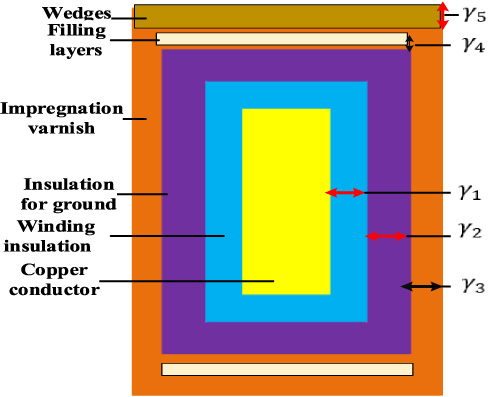
Simplified equivalent structural model of the slot winding.
It is seen in Fig. 8 in a different direction; the thermal conductivity is not the same in-between winding and lamination, and their thermal resistance for conduction can be estimated as follows:
The heat exchange between rotor and stator is convection. The stationary fluid’s effective thermal conductivity is used for simulating an air gap’s airflow thermal conductivity to minimize the estimation for convective heat transfer. An air gap equivalent thermal conductivity is expressed in [23].
High-speed PMSM material thermal conductivities
Thermal conduction can be estimated generally as:
The equivalent thermal conductivity when evaluating with or without clearance mechanism is written by:
The air gap’s thermal conductance of an air-cooled machine is calculated by [24].
The heat transport in an end space is complicated, and [25] discusses it in detail. The following is a well-known equation for introducing definitions inside end space in a different way:
Sensitivity analysis by LPTN is helpful in terms of identifying which thermal resistance has more influence on mitigating temperature rise of the stator as in [26], and normally thermo-physical properties for the dissimilar material are taken into consideration as in [27]. This paper, due to consideration of thermal conductivities and thermal conductance, this current sensitivity analysis considers an equivalent thermal resistance of them. Table 5 shows both the thermal resistances and their respective names.
Thermal resistance names with equivalent parameters
Thermal resistance names with equivalent parameters
The sensitivity analysis focuses on lowering the value of the aforementioned thermal resistance by a particular percentage through calculating the temperature difference between the maximum winding temperature using the initial parameter and the maximum winding temperature using an optimal parameter. Table 6 shows the sensitivity findings for each parameter and reduced percentages of slot winding maximum temperature.
Increased air volume flow rate improves convective heat transfer coefficient along the air gap, lowering convective thermal resistance along this passage. As a result, as shown in Fig. 9(i), the anticipated convective thermal resistance along the airgap duct begins to reduce as the air volume’s flow rate increases, resulting in increased heat transfer 9(ii). Figure 9(iii) shows that increasing the convective heat transfer coefficient for driven air outside the slot winding has a limit in lowering the slot winding maximum temperature, as shown by the dotted lines, which is equivalent to 75.6 K. Hence, the maximum difference in temperature between the present heat transfer (1012 W/m2⋅ K) and the infinite heat transfer coefficient is about 5.6 K. Based on the observation from Fig. 9, an important conclusion can be drawn. The next parameter that can make the maximum slot winding temperature lower must be between winding and liner. Because based on the sensitivity analysis, enhancing the airgap coefficient of heat transfer by increasing air volume’s possess a certain limit. Therefore, special attention to slot winding insulation must be given subject to a decrease in maximum winding temperature, which is inevitable for protecting the winding insulation class against deterioration.
Influence for slot’s liner thermal conductivity
Heat transfer and maximum temperature mitigation for the slot winding are improved by selecting slot liner material with an optimal thermal conductivity value. Therefore, this analysis is carried out to analyze the influence of the slot’s liner conductivity on the maximum temperature of slot winding. Figure 10 shows the slot winding maximum temperature predicted by the presented LPTN for various slots linear thermal conductivity ranging from 0.01 to 1.5 (W/m ⋅ K). Figure 10(i) shows that when the value of the enhanced thermal conductivity is less than one, the effect of the slot’s liner thermal conductivity on the maximum temperature of slot winding temperature is significant. When the enhanced thermal conductivity is more than one, however, the effect of the slot’s liner thermal conductivity on the maximum temperature of slot winding is smaller, as illustrated in Fig. 10(ii). For the proposed LPTN model shown in Fig. 6, an optimized slot’s liner thermal conductivity of (0.21) is used.
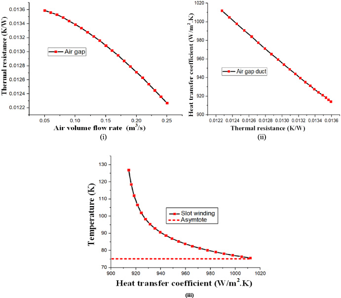
Influence of convective heat transfer coefficient in the airgap duct on slot winding maximum temperature. (i) Influence of air volume’s flow rate on thermal convective resistance. (ii) Influence of an air gap thermal convective resistance on air gap’s heat transfer. (iii) Influence of air gap’s coefficient of convective heat transfer on the maximum temperature for the slot winding.
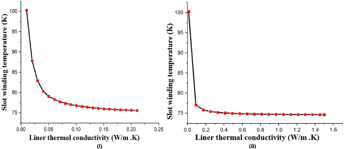
Influence of liner thermal conductivity on the maximum temperature of slot winding. (i) Liner thermal conductivity less than one. (ii) Liner thermal conductivity greater than one.
Within an electrical machine, there are several types of interface contacts. The interface contact between lamination and hosing is crucial for TEFC machines because the entire heat is being removed from this area to a housing [18]. The interface contact arises from defects between surfaces of solid material [28]. It is modelled as an equivalent air gap in the LPTN of an electrical machine using this method. It is very difficult to estimate an equivalent length of interface gap due to its dependency on the material manufacturing process, hardness and interface pressure [29]. Therefore, the prediction for high-speed PMSM’s thermal performance by LPTN also depends on contact resistance inside the machine, including lamination to housing and slot liner to lamination [30]. Mills presents data in [31], which can be used as an equivalent air gap by considering the thermal conductivity of air as 0.026 W/m/K. In general, an electrical material interface gap for aluminum–aluminum ranges from 5e-4 to 2.5e-3 mm, aluminum to iron ranges from 6e-4 to 6e-3 mm as in [31]. This paper considers an optimal interface gap between stator lamination and housing as 0.03, representing how excellent stator roughness of the outer lamination gets prepared before the housing is fitted. It is shown in Fig. 11 when the interface contact’s roughness for the lamination to housing’s increases, the maximum temperature of slot-winding likewise increases; hence, this interface contact must be smooth in order to decrease the maximum temperature of slot-winding.
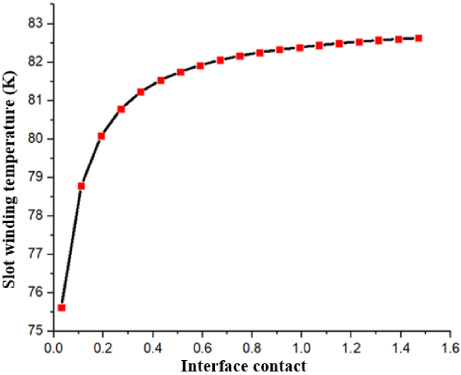
Influence of interface contact for lamination to housing on maximum temperature slot winding.
Summary of the machine thermal sensitivity analysis
The equilibrium thermal equations are developed using the energy conservation principle. This expression gives an equilibrium equation for electric machine structure in a steady-thermal state condition:
An expression (27) gives the equation for the thermal equilibrium of an air cooling fluid.
For steady-thermal state conditions, the relationship between thermal conductance and heat source provides every node’s temperature, which is calculated using an equation (29). The thermal conductance matrix (Gnxn) dimension is taken as n = 24.
Thermal conductance matrix (G) is solved by adopting one of the following elimination methods, i.e., Jacobi-cholsely, Gauss, Gauss-seidel and conjugate gradient.
Figure 12 depicts the flowchart of the entire temperature calculation method. Based on the proposed LPTN shown in Fig. 6, the machine structural parts’ temperatures, including winding, yoke, teeth and cooling air temperature, are given in Tables 7 and 8, respectively. The findings demonstrate that after winding thermal optimization by LPTN sensitivity analysis, the slot winding close an outlet air possesses the highest temperature (75.6 K) for this machine with TEFCAVS, which is far below the maximum temperature of the winding insulation class E (120 K).
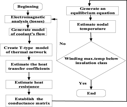
Flowchart of an entire methodology.
Estimated maximum temperature of the machine
Temperature for the cooling air
Because a tradeoff in magnetic material selection, motor topology, and controls approach allows for efficient and highly efficient machine design and development, the following assumptions were taken into account during the design of the proposed machine accordingly:
(i) In the electromagnetic analysis: (1) the stator and rotor iron’s relative permeability is infinite, i.e., it does not saturate. (2) All non-iron components (the winding and the magnets) have a relative permeability of 1.0. (3) Permanent magnets’ remanence flux density is proportional to; 1.15. (4) Magnets do not lose their magnetization. (5) Based on dynamic response and electromagnetic load, the actual dimension is chosen to obtain the actual high-speed PMSM size. (6) Assume that the drive motor’s four primary indicators, torque density in relation to thermal, energy efficiency, constant power range, and active material cost, all match the design requirements for the blower application.
(ii) In the thermal analysis, (1) because heat transfer through radiation is minimal, it is ignored. (2) An effect for end windings on thermal behaviour is not taken into account. (3) Thermal capacitances have no effect on the steady-state thermal performance and therefore are neglected. (4) In each region, heat sources are assumed to distribute evenly. (5) The temperature of the air coolant is not constant.
(iii) In the experimental validation, models of machine drives, such as inverters, impose several restrictions; it is assumed that the drive operates as an infinite voltage bus with a power factor of one and perfectly sinusoidal current and voltage waveforms in time.
Validation for the LPTN has been demonstrated in numerous works of literature for both transient and steady-state situations of various types of motors, including [32–35]. An explicit explanation for a resistive network of each component for the lumped parameter thermal network considering their material properties and geometric is presented in [34]. A spatial discretization, especially for windings, is provided in the recent model of LPTN works as in [36,37]. Notwithstanding, the detail of high-speed PMSM airflow networks with the LPTN has been given less attention. This validation provides a detailed comparison of LPNT and experimental results, which concentrate on stator since the hotspot temperatures of the high-speed PMSM are located in the winding. Previously presented validation of LPTN and experimental results concentrated on analysis for individual temperature points, but not how the airflow and every stator component contribute to the high-speed PMSM’s winding temperature rise. This paper presents a different concept by investigating temperature profiles along three different passages for high-speed PMSM; i.e., special attention is given to a slot winding, interface-contact and air gap.
Because the PM losses are negligible due to the segmentation of PMs, which reduces the PM’s eddy current losses, only two types of losses, namely, copper and iron, were considered in the experimental validation. Furthermore, given its considerable thermal inertia, it is assumed that the rotor is isothermal.
Heat source determination
The setup for measuring the loss of the winding where a power supply with variable frequency sinusoidal current is applied to energize the copper winding is illustrated in Fig. 13. The voltage, current, and power were measured by a power analyzer (UT285A) that permits us to consider resistance variation with a frequency.
Copper winding loss determination
For an experimental test, the copper winding loss is derived from the difference between measured total power inputs by the power analyzer and coreless calculated by 2D FEM. The total copper winding loss summates two components, slot and end winding, which is expressed by:
It can be seen that from Eq. (31), both the components of the copper winding loss depend on frequency and temperature. Under DC operation, estimating DC winding resistance and its total length (active and end winding) determine these two loss components easily.
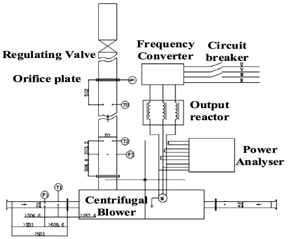
Schematic diagram of an experimental setup.
The resistivity for the winding is amended by (32), 𝜌
O
representing the resistivity of the copper winding, at T
O
= 20 K 𝜌
O
=1.68 ×10⁻⁸ Ωm, 𝛼 = 3.93 × 10⁻³, where 𝛼 represents resistivity coefficient of temperature and T represents an operating temperature point.
The above Eq. (32) will not be used directly to amend an operating temperature during an AC operation because DC and AC copper winding loss components depend on the temperature in a distinct way as in [38–41]. The AC copper winding loss dependency on temperature is given by the expression (33) as in [42].
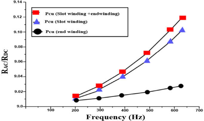
AC copper winding loss factor when I rms = 557.8 and T O = 20 K.
An AC copper winding loss factor against frequency is shown in Fig. 14. It can be seen that across end winding, the loss factor (R
AC
∕R
DC
) is smaller related to the slot winding because the flux leakage inside the slot winding is greater than the region of an end winding, where the winding is enclosed with air [44,45]. Hence, the proximity effect is lower along an end winding. The power analyzer measures the input power of the stator core. The finite element (FE) iron loss is subtracted from the measured total input power to accurately estimate AC copper winding resistance.
It becomes experimentally impossible to separate stator iron loss from the power measured by the power analyzer (copper loss and iron loss) [46,47]. Hence, an accurate iron loss estimation is needed; due to this reason, finite element simulation for the stator core is conducted with similar experimental current and frequency values. The estimation for the core loss is conducted with pure sine wave excitation; the results with varying frequency and flux density are given in Fig. 15. It can be seen that core loss increases with an increase in frequency and flux density.
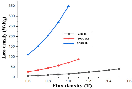
Correlation between estimated core loss with flux density and frequency.
A platinum-resistant thermometer (PT100) sensors were positioned in both slot and end winding for temperature measurement, which can measure temperature between −200 °C and 650 °C and has an accuracy of ±0.1 °C; with the nominal resistance of 100 Ω at 1 °C. These PT100 sensors are positioned at 1∕4, 1∕2, or 3∕4 of the winding span. Furthermore, one PT100 is positioned at both end winding regions, as illustrated in Fig. 16(i). The centrifugal blower serves as the load for the prototype. The power analyzer WT1804E directly measures the input power of the motor, and the power of the motor shaft is indirectly derived from the load of the impeller. The temperature of the winding is recorded for different frequencies. The temperature test for one excitation point is conducted until a thermal steady state is met, and it is stopped when the temperature rise of the winding is lower than 1 °C over 30 min, as shown in Fig. 17. It can be seen from Fig. 17 considerable difference between slot windings temperature and end windings temperature is recorded. This mismatch is due to differences in heat pathways because the generated heat within an end winding is released easily to the cooling air. In contrast, heat generated by the slot winding has to cross through the stator core before being dissipated to the cooling air. The temperature of slot-winding is considered the hotspot in this study, so it receives extra attention. Tables 9 and 10 show the temperature of the machine structure and cooling air, respectively. The predicted and experimental results are then correlated; the error (ϵ) between the experimented and predicted stator copper winding is determined as given in Table 10 using an Eq. (35).

Experimental setup. (i) The sensors arrangement of the temperature measurement in one phase winding. (ii) 1/3 cut view of the prototype. (iii) Prototype setup for 225 kW high-speed PMSM for air suspension centrifugal blower application.
To check the accuracy of the LPTN model, predicted and measured winding temperature values are compared, and a percentage error demonstrates the indicators for assessing the proposed LPTN accuracy. Slot-windings have the highest error than end winding due to boundary temperature assumption inside the slot and ratio of an internal thermal conductivity to the internal heat source. The maximum error of 10.2% is obtained for the slot winding, which illustrates good agreement between LPTN estimated and test data; therefore, it can be concluded that the proposed LPTN can predict the high-speed PMSM temperature accurately.
Comparison of the estimated and measured maximum temperature for winding

The winding steady-state maximum temperature at a different frequency.
Temperature measured for ambient and air coolant
When the winding current density increases, the prototype power output increases, and the copper winding’s temperature likewise increases. Based on the results presented in Table 11, the desired copper winding current density and temperature rise of winding for high-speed PMSM having similar power output to the prototype is selected. The sensitivity analysis considers the winding insulation class using the proposed optimal thermal parameters.
Calibration process
Calibration is conducted to confirm the accuracy of the LPTN. Firstly, the test is conducted under an inlet air coolant temperature of 20 K and 30 K, and then the next task is to calibrate the coefficients for thermal convection. For this purpose, LPTN that includes a heat source and thermal convection resistances is mandatory for determining certain nodes’ temperature. The slot winding is axially connected to an end winding, radially connected to the teeth and yoke, as shown in Fig. 18.
Slot winding maximum temperature at different current densities
Slot winding maximum temperature at different current densities
The thermal resistance depends on both coefficient of forced convection and thermal conductivity, this paper, more attention is given to thermal convection resistance as the conduction resistances are considered to be known through their material thermal conductivity and mechanical parameters.
Simplified reduced thermal network of the prototype for the calibration process.
Convection thermal resistances are unknown; when considering all the generated heat extracted within the winding via forced convection, the convection resistance between winding and inner air can be estimated from the measured joule loss and temperature [48].
The force convection thermal resistance between housing and heat sink can be estimated by:
Steady-state calibrated parameters
The methodology adopted to estimate the heat transfer coefficient is that using experimental test results of temperature and loss, the thermal convection resistance is estimated first. The forced convection coefficient is determined by the nonlinear least square method, as shown in Fig. 19. It is shown in Fig. 19(ii) as the inlet coolant’s temperature increases, the maximum temperature for the slot winding also increases; this means that decreasing the coolant’s temperature improves the cooling capability of the slot winding. Furthermore, the coolant temperature has a distinct effect on the convective coefficient for housing and slot winding. The calibrated coefficient for the slot winding is higher than for housing during the range of inlet air coolant’s temperature of (10 K–20 K), but the contrary result is shown for the range of 20 K–30 K; it has been shown that the speed of the machine hardly influences the calibrated coefficient. The increase in coolant’s temperature reduces the heat exchange between cold air and heat source components and decreases heat exchange time.
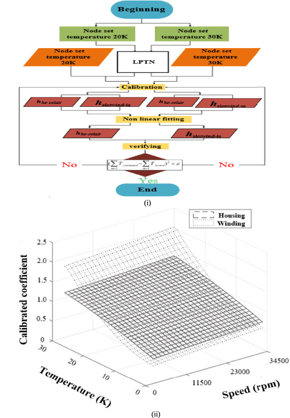
Calibration process. (i) Schematic diagram for the calibration process. (ii) Calibrated convection coefficient for housing and slot winding.
Figure 20 shows the confirmation for an improved LPTN’s accuracy with calibrated coefficients. The steady-state thermal tests of the prototype at the rated condition of (34500 rpm) were conducted using an experimental setup shown in Fig. 16, and the results include end winding and slot winding temperature. The corresponding estimation results were obtained using calibrated coefficients with the proposed LPTN. The only result of the slot winding is shown in Fig. 20, being the hotspot of the machine; thus, it is given more attention. It can be seen that the estimated result with calibrated coefficients becomes closer to the test values than with un-calibrated. The error of estimation with calibrated coefficient is small between inlet coolant’s temperature of 10 K–18 K, gradually increases with the range of 18 K–24 K, then finally decline between 24 K and 30 K. The minimum and maximum errors are 4.8% and 10.2%, respectively.
The proposed LPTN considers the change in cooling ability due to the air coolant’s temperature with its calibrated coefficients, which is along the line for an actual state of heat transfer compared with un-calibrated. The calibration considers experimental test results with 20 K and 30 K. The above calibration for convection thermal coefficients alongside coolant’s temperature will enhance the accuracy of the LPTN thermal analysis for high-speed PMSM with axial TEFCAVS.

Confirmation for an improved LPTN’s accuracy of the slot winding maximum temperature.
In this paper, thermal analysis of high-speed PMSM with TEFCAVS for centrifugal blower applications is carried out. Sensitivity analysis is conducted by the LPTN method to find out the thermal parameter that greatly influences maximum temperature rise. Special attention is given to the slot winding for being the hot spot of the machine and sensitive to temperature rise when heat is not properly dissipated. The main findings are summarized as follows:
(1) Airflow model is included before LPTN thermal modelling, which allows the choice of an air-cooling fan capacity and ensures an air volume is provided adequately for uniform slot winding temperature distribution in the LPTN.
(2) Sensitivity analysis is conducted by LPTN on various parameters affecting heat transfer; this is beneficial in terms of finding parameters that can improve heat transfer or mitigate temperature rise in the slot winding.
Convective heat transfer of an air gap is improved by increasing an air volume flow rate, decreasing convective thermal resistance along this passage. It has been illustrated that enhancing the air volume’s flow rate to increase the airgap coefficient of convective heat transfer for the forced air outside the slot winding possesses a certain limit in reducing maximum slot winding temperature. Because the further increase in air volume beyond that limit (0.25 m3/s) will not enhance the convective heat transfer airgap coefficient, it generates more windage losses, making the heat transfer difficult and affecting the heat exchange between them slot winding and cooling air passing along the air gap duct.
Sensitivity analysis also shows that enhancing the airgap coefficient of heat transfer will not give enough decrease in slot-winding temperature. Therefore, special attention must be paid to selecting slot winding insulation material subject to a maximum slot winding temperature decrease.
(3) Heat transfer and maximum temperature mitigation for the slot winding are improved by selecting a high thermal conductivity of liner material. Investigation shows that the influence of slot’s liner thermal conductivity on mitigating slot winding temperature is great only when the value of the increased thermal conductivity is less than one, and the influence is less when the increased thermal conductivity is greater than one.
Sensitivity results show that slot liner material with thermal conductivity less than one (0.21) generates an optimal maximum slot winding temperature of 75.6 K. This is inevitable for protecting the winding insulation class against deterioration because an unnoticeable decrease in maximum slot winding temperature is seen when its slot liner thermal conductivity is greater than one.
(4) To confirm the LPTN model’s accuracy, estimated and measured values for the winding temperature are compared, which an error value depicts the criteria for measuring the LPTN accuracy. Slot-windings have the highest error than end winding. The minimum and maximum errors of 4.8% and 10.2% were obtained for the slot winding, which illustrates a good agreement between LPTN simulation and test data. Therefore, it can be concluded that LPTN can accurately predict the high-speed PMSM’s slot winding temperature, which is confirmed through the Calibration process.